Motherboard DIY Troubleshooting Guide
Page 39
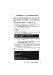
User recovery requested. Reading file "P4V8XX.rom". Rebooting. 2-5 User recovery requested. Checking for floppy... Completed. Starting BIOS recovery... Floppy found! Starting BIOS recovery... Checking for floppy... Start flashing... Flashed successfully.
User recovery requested. Reading file "P4V8XX.rom". Rebooting. 2-5 User recovery requested. Checking for floppy... Completed. Starting BIOS recovery... Floppy found! Starting BIOS recovery... Checking for floppy... Start flashing... Flashed successfully.
Motherboard DIY Troubleshooting Guide
Page 40
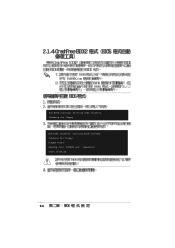
Reading file "P4V8XX.rom". Start flashing... 2-6 Bad BIOS checksum. Completed. Starting BIOS recovery... Checking for floppy... Starting BIOS recovery... Checking for floppy... Bad BIOS checksum. Floppy found!
Reading file "P4V8XX.rom". Start flashing... 2-6 Bad BIOS checksum. Completed. Starting BIOS recovery... Checking for floppy... Starting BIOS recovery... Checking for floppy... Bad BIOS checksum. Floppy found!
Motherboard DIY Troubleshooting Guide
Page 41
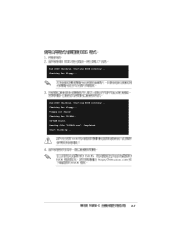
Bad BIOS checksum. Checking for floppy... Starting BIOS recovery... Checking for CD-ROM... Reading file "P4V8XX.rom". Start flashing... 2-7 Floppy not found . Bad BIOS checksum. CD-ROM found ! Starting BIOS recovery... Checking for floppy... Completed.
Bad BIOS checksum. Checking for floppy... Starting BIOS recovery... Checking for CD-ROM... Reading file "P4V8XX.rom". Start flashing... 2-7 Floppy not found . Bad BIOS checksum. CD-ROM found ! Starting BIOS recovery... Checking for floppy... Completed.
Motherboard DIY Troubleshooting Guide
Page 47
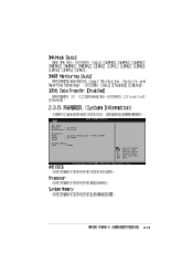
Change Option F1 General Help F10 Save and Exit ESC Exit 2-13 AMI BIOS Version : 08.00.09 Build Date : 07/07/03 Processor Type Speed Count : Intel(R) Pentium(R) 4 CPU 1500MHz : 1500 MHz : 1 System Memory Size : 256MB Select Screen Select Item +-
Change Option F1 General Help F10 Save and Exit ESC Exit 2-13 AMI BIOS Version : 08.00.09 Build Date : 07/07/03 Processor Type Speed Count : Intel(R) Pentium(R) 4 CPU 1500MHz : 1500 MHz : 1 System Memory Size : 256MB Select Screen Select Item +-
Motherboard DIY Troubleshooting Guide
Page 55
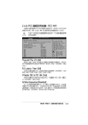
...] [64] [Yes] [Disabled] [Enabled] IRQ3 IRQ4 IRQ5 IRQ7 IRQ9 IRQ10 IRQ11 IRQ14 IRQ15 [Available] [Available] [Available] [Available] [Available] [Available] [Available] [Available] [Available] NO: Lets the bIOS configure all the devices in the sections below may cause system to malfunction. YES: Lets the operating system configure Plug and Play (PnP) devices not...
...] [64] [Yes] [Disabled] [Enabled] IRQ3 IRQ4 IRQ5 IRQ7 IRQ9 IRQ10 IRQ11 IRQ14 IRQ15 [Available] [Available] [Available] [Available] [Available] [Available] [Available] [Available] [Available] NO: Lets the bIOS configure all the devices in the sections below may cause system to malfunction. YES: Lets the operating system configure Plug and Play (PnP) devices not...
Motherboard DIY Troubleshooting Guide
Page 61
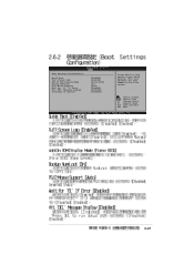
Change Option F1 General Help F10 Save and Exit ESC Exit 2-27 Boot Settings Configuration Quick Boot Full Screen Logo Add On ROM Display Mode Bootup Num-Lock PS/2 Mouse Support Wait for 'F1' If Error Hit 'DEL' Message Display Interrupt 19 Capture [Enabled] [Enabled] [Force BIOS] [On] [Auto] [Enabled] [Enabled]\ [Disabled] Allows BIOS to boot the system. Select Screen Select Item +- This will decrease the time needed to skip certain tests while booting.
Change Option F1 General Help F10 Save and Exit ESC Exit 2-27 Boot Settings Configuration Quick Boot Full Screen Logo Add On ROM Display Mode Bootup Num-Lock PS/2 Mouse Support Wait for 'F1' If Error Hit 'DEL' Message Display Interrupt 19 Capture [Enabled] [Enabled] [Force BIOS] [On] [Auto] [Enabled] [Enabled]\ [Disabled] Allows BIOS to boot the system. Select Screen Select Item +- This will decrease the time needed to skip certain tests while booting.
Motherboard DIY Troubleshooting Guide
Page 70
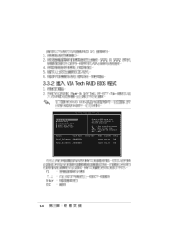
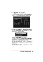
RAID BIOS Ver 1.XX Create Array Delete Array Create/Delete Spare Select Boot Array Serial Number View Channel Drive Name Serial_Ch0 Master XXXXXXXXXX Serial_Ch1 Master XXXXXXXXXX Create a RAID array with the hard disk attached to VIA IDE controller F1 : View Array/Disk Status , : Move to next item Enter: Confirme the selection ESC : Exit Array Name Mode Size(GB) Status xxxxx xxx.xx Hdd xxxxx xxx.xx Hdd 3-6 VIA Tech.
RAID BIOS Ver 1.XX Create Array Delete Array Create/Delete Spare Select Boot Array Serial Number View Channel Drive Name Serial_Ch0 Master XXXXXXXXXX Serial_Ch1 Master XXXXXXXXXX Create a RAID array with the hard disk attached to VIA IDE controller F1 : View Array/Disk Status , : Move to next item Enter: Confirme the selection ESC : Exit Array Name Mode Size(GB) Status xxxxx xxx.xx Hdd xxxxx xxx.xx Hdd 3-6 VIA Tech.
Motherboard DIY Troubleshooting Guide
Page 71
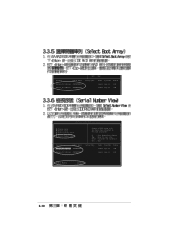
VIA Tech. RAID BIOS Ver 1.xx Auto Setup For Data Security Array Mode RAID 1 (Mirroring) Select Disk Drives Start Create Process Create a RAID array with the hard disk attached to VIA IDE controller F1 : View Array/Disk Status , : Move to next item Enter: Confirm the selection ESC : Exit Channel Drive Name Serial_Ch0 Master XXXXXXXXXX Serial_Ch1 Master XXXXXXXXXX Array Name Mode Size(GB) Status xxxxx xxx.xx Hdd xxxxx xxx.xx Hdd RAID 0 for performance RAID 1 for data protection RAID 0/1 RAID SPAN for capacity 3-7
VIA Tech. RAID BIOS Ver 1.xx Auto Setup For Data Security Array Mode RAID 1 (Mirroring) Select Disk Drives Start Create Process Create a RAID array with the hard disk attached to VIA IDE controller F1 : View Array/Disk Status , : Move to next item Enter: Confirm the selection ESC : Exit Channel Drive Name Serial_Ch0 Master XXXXXXXXXX Serial_Ch1 Master XXXXXXXXXX Array Name Mode Size(GB) Status xxxxx xxx.xx Hdd xxxxx xxx.xx Hdd RAID 0 for performance RAID 1 for data protection RAID 0/1 RAID SPAN for capacity 3-7
Motherboard DIY Troubleshooting Guide
Page 74
... Serial_Ch0 Master XXXXXXXXXX Serial_Ch1 Master XXXXXXXXXX ESC : Exit Array Name Mode Size(GB) Status xxxxx xxx.xx Hdd xxxxx xxx.xx Hdd VIA Tech. RAID BIOS Ver 1.xx Create Array Delete Array Create/Delete Spare Select Boot Array Serial Number View Channel Drive Name Serial_Ch0 Master XXXXXXXXXX Serial_Ch1 Master XXXXXXXXXX Create...
... Serial_Ch0 Master XXXXXXXXXX Serial_Ch1 Master XXXXXXXXXX ESC : Exit Array Name Mode Size(GB) Status xxxxx xxx.xx Hdd xxxxx xxx.xx Hdd VIA Tech. RAID BIOS Ver 1.xx Create Array Delete Array Create/Delete Spare Select Boot Array Serial Number View Channel Drive Name Serial_Ch0 Master XXXXXXXXXX Serial_Ch1 Master XXXXXXXXXX Create...
P4V8X-X User Manual
Page 3
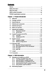
Features Contents Notices v Safety information vi About this guide vii ASUS contact information viii P4V8X-X specifications summary ix Chapter 1: Product introduction 1.1 Welcome 1-2 1.2 Package contents 1-2 1.3 Special features 1-2 1.4 Motherboard components 1-4 ...1-18 Chapter 2: BIOS information 2.1 Managing and updating your BIOS 2-2 2.1.1 Creating a bootable floppy disk 2-2 2.1.2 Using AFUDOS to update the BIOS 2-2 2.1.3 Using AFUDOS to copy BIOS from PC 2-4 2.1.4 Using ASUS EZ Flash to update the BIOS 2-5 2.1.5 Using ASUS CrashFree BIOS 2 2-6 2.2 BIOS Setup program 2-8 iii
Features Contents Notices v Safety information vi About this guide vii ASUS contact information viii P4V8X-X specifications summary ix Chapter 1: Product introduction 1.1 Welcome 1-2 1.2 Package contents 1-2 1.3 Special features 1-2 1.4 Motherboard components 1-4 ...1-18 Chapter 2: BIOS information 2.1 Managing and updating your BIOS 2-2 2.1.1 Creating a bootable floppy disk 2-2 2.1.2 Using AFUDOS to update the BIOS 2-2 2.1.3 Using AFUDOS to copy BIOS from PC 2-4 2.1.4 Using ASUS EZ Flash to update the BIOS 2-5 2.1.5 Using ASUS CrashFree BIOS 2 2-6 2.2 BIOS Setup program 2-8 iii
P4V8X-X User Manual
Page 4
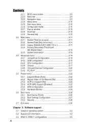
Safeguards Contents 2.2.1 2.2.2 2.2.3 2.2.4 2.2.5 2.2.6 2.2.7 2.2.8 2.2.9 BIOS menu screen 2-9 Menu bar 2-9 Navigation keys 2-9 Menu items 2-10 Sub-menu items 2-10 Configuration fields 2-10 Pop-up window 2-10 Scroll bar 2-10 General help 2-...
Safeguards Contents 2.2.1 2.2.2 2.2.3 2.2.4 2.2.5 2.2.6 2.2.7 2.2.8 2.2.9 BIOS menu screen 2-9 Menu bar 2-9 Navigation keys 2-9 Menu items 2-10 Sub-menu items 2-10 Configuration fields 2-10 Pop-up window 2-10 Scroll bar 2-10 General help 2-...
P4V8X-X User Manual
Page 9
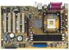
P4V8X-X specifications summary CPU Chipset Front Side Bus (FSB) Memory Expansion slots Storage Audio LAN USB AI Overclocking Special features Back panel I/O Socket 478 for Intel&#... CPU and Memory voltage adjustable SFS (Stepless Frequency Selection) at 1 MHz increment Adjustable FSB/DDR ratio ASUS C.P.R. (CPU Parameter Recall) Power Loss Restart ASUS C.P.R. (CPU Parameter Recall) support S/PDIF out interface ASUS EZ Flash CrashFree BIOS 2 ASUS MyLogo2 1 x Parallel port 1 x Serial port 1 x PS/2 keyboard port 1 x PS/2 mouse port 4 x USB 2.0 ports 1 x S/PDIF out 1 x RJ-45 port...
P4V8X-X specifications summary CPU Chipset Front Side Bus (FSB) Memory Expansion slots Storage Audio LAN USB AI Overclocking Special features Back panel I/O Socket 478 for Intel&#... CPU and Memory voltage adjustable SFS (Stepless Frequency Selection) at 1 MHz increment Adjustable FSB/DDR ratio ASUS C.P.R. (CPU Parameter Recall) Power Loss Restart ASUS C.P.R. (CPU Parameter Recall) support S/PDIF out interface ASUS EZ Flash CrashFree BIOS 2 ASUS MyLogo2 1 x Parallel port 1 x Serial port 1 x PS/2 keyboard port 1 x PS/2 mouse port 4 x USB 2.0 ports 1 x S/PDIF out 1 x RJ-45 port...
P4V8X-X User Manual
Page 10
...P4V8X-X specifications summary Internal I/O BIOS features Industry standard Manageability Power Requirement Support CD contents Form Factor 2 x USB 2.0 connector for 4 additional USB ports CPU/Chassis fan connectors 20-pin/4-pin ATX 12V power connectors CD/AUX connectors Game/MIDI connector 10-1 pin front panel connector 4Mb Flash ROM, AMI BIOS, ACPI, PnP, DMI2.0, ASUS... EZ Flash, ASUS MyLogo2 PCI 2.2, USB 2.0/1.1 DMI 2.0, WOL/WOR by PME, chassis intrusion ATX power supply ...
...P4V8X-X specifications summary Internal I/O BIOS features Industry standard Manageability Power Requirement Support CD contents Form Factor 2 x USB 2.0 connector for 4 additional USB ports CPU/Chassis fan connectors 20-pin/4-pin ATX 12V power connectors CD/AUX connectors Game/MIDI connector 10-1 pin front panel connector 4Mb Flash ROM, AMI BIOS, ACPI, PnP, DMI2.0, ASUS... EZ Flash, ASUS MyLogo2 PCI 2.2, USB 2.0/1.1 DMI 2.0, WOL/WOR by PME, chassis intrusion ATX power supply ...
P4V8X-X User Manual
Page 13
... Bus (USB) 2.0 specification, extending the connection speed from a floppy diskette or recovery CD when BIOS code and data are corrupted during upgrade or when invaded by a virus. ASUS P4V8X-X motherboard 1-3 Integrated 10/100 LAN The onboard LAN controller is onboard to 3.2GB/s data transfer... transfer rate, and software compatibility with an ACPI management function to provide efficient power management for advanced operating systems. CrashFree BIOS 2 CrashFree BIOS 2 allows users to create Serial ATA RAID0 and RAID1 configurations using PC3200/2700/2100 non-ECC DDR DIMMs to deliver ...
... Bus (USB) 2.0 specification, extending the connection speed from a floppy diskette or recovery CD when BIOS code and data are corrupted during upgrade or when invaded by a virus. ASUS P4V8X-X motherboard 1-3 Integrated 10/100 LAN The onboard LAN controller is onboard to 3.2GB/s data transfer... transfer rate, and software compatibility with an ACPI management function to provide efficient power management for advanced operating systems. CrashFree BIOS 2 CrashFree BIOS 2 allows users to create Serial ATA RAID0 and RAID1 configurations using PC3200/2700/2100 non-ECC DDR DIMMs to deliver ...
P4V8X-X User Manual
Page 15
...integrated peripheral controller supports various I /O interface, AC'97 interface and PCI 2.2 interface. 10 Floppy disk connector. This 4Mb firmware contains the programmable BIOS program. 13 Super I /O functionality. This Low Pin Count (LPC) interface provides the commonly used Super I /O controller. A 478-pin ... ribbon cable. 7 AGP 8X slot. The chipset supports a highperformance floppy disk controller for 3D graphical applications. 8 SATA connectors. ASUS P4V8X-X motherboard 1-5 One side of the floppy disk cable. 11 Standby power LED. This LED lights up to 3GB system memory using...
...integrated peripheral controller supports various I /O interface, AC'97 interface and PCI 2.2 interface. 10 Floppy disk connector. This 4Mb firmware contains the programmable BIOS program. 13 Super I /O functionality. This Low Pin Count (LPC) interface provides the commonly used Super I /O controller. A 478-pin ... ribbon cable. 7 AGP 8X slot. The chipset supports a highperformance floppy disk controller for 3D graphical applications. 8 SATA connectors. ASUS P4V8X-X motherboard 1-5 One side of the floppy disk cable. 11 Standby power LED. This LED lights up to 3GB system memory using...
P4V8X-X User Manual
Page 20
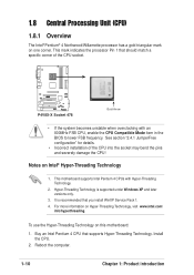
This motherboard supports Intel Pentium 4 CPUs with an 800MHz FSB CPU, enable the CPU Compatible Mode item in the BIOS to lower FSB frequency. For more information on one corner. This mark indicates the processor Pin 1 that you install WinXP...Reboot the computer. 1-10 Chapter 1: Product introduction See section "2.4.1 JumperFree configuration" for details. • Incorrect installation of the CPU socket. ® P4V8X-X P4V8X-X Socket 478 Gold Arrow • If the system becomes unstable when overclocking with Hyper-Threading Technology. 2. Buy an Intel Pentium 4 CPU that supports ...
This motherboard supports Intel Pentium 4 CPUs with an 800MHz FSB CPU, enable the CPU Compatible Mode item in the BIOS to lower FSB frequency. For more information on one corner. This mark indicates the processor Pin 1 that you install WinXP...Reboot the computer. 1-10 Chapter 1: Product introduction See section "2.4.1 JumperFree configuration" for details. • Incorrect installation of the CPU socket. ® P4V8X-X P4V8X-X Socket 478 Gold Arrow • If the system becomes unstable when overclocking with Hyper-Threading Technology. 2. Buy an Intel Pentium 4 CPU that supports ...
P4V8X-X User Manual
Page 24
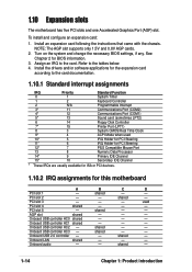
...5 - AGP slot shared - - - Onboard USB controller HC0 shared - - - Onboard audio - - Install the drivers and/or software applications for BIOS information. 3. PCI slot 2 - - To install and configure an expansion card: 1. 1.10 Expansion slots The motherboard has five PCI slots and one Accelerated...) slot. Install an expansion card following the instructions that came with the chassis. Turn on the system and change the necessary BIOS settings, if any. Assign an IRQ to the tables below. 4. Onboard USB controller HC2 - shared - - Onboard USB ...
...5 - AGP slot shared - - - Onboard USB controller HC0 shared - - - Onboard audio - - Install the drivers and/or software applications for BIOS information. 3. PCI slot 2 - - To install and configure an expansion card: 1. 1.10 Expansion slots The motherboard has five PCI slots and one Accelerated...) slot. Install an expansion card following the instructions that came with the chassis. Turn on the system and change the necessary BIOS settings, if any. Assign an IRQ to the tables below. 4. Onboard USB controller HC2 - shared - - Onboard USB ...
P4V8X-X User Manual
Page 26
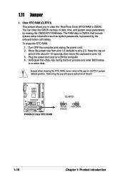
The RAM data in CMOS. Turn OFF the computer and unplug the power cord. 2. Removing the cap will cause system boot failure! ® P4V8X-X P4V8X-X Clear RTC RAM CLRTC1 12 Normal (Default) 23 Clear CMOS 1-16 Chapter 1: Product introduction To erase the RTC RAM: 1. Move the jumper cap from pins 1-2 (... erasing the CMOS RTC RAM data. Plug the power cord and turn ON the computer. 4. Hold down the key during the boot process and enter BIOS setup to pins 2-3. You can clear the CMOS memory of date, time, and system setup parameters by the onboard button cell battery. Keep the cap...
The RAM data in CMOS. Turn OFF the computer and unplug the power cord. 2. Removing the cap will cause system boot failure! ® P4V8X-X P4V8X-X Clear RTC RAM CLRTC1 12 Normal (Default) 23 Clear CMOS 1-16 Chapter 1: Product introduction To erase the RTC RAM: 1. Move the jumper cap from pins 1-2 (... erasing the CMOS RTC RAM data. Plug the power cord and turn ON the computer. 4. Hold down the key during the boot process and enter BIOS setup to pins 2-3. You can clear the CMOS memory of date, time, and system setup parameters by the onboard button cell battery. Keep the cap...
P4V8X-X User Manual
Page 29
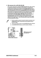
...UltraDMA100/66 IDE devices, use the 80-conductor IDE cable. ® P4V8X-X P4V8X-X IDE Connectors SEC_IDE1 PRI_IDE1 NOTE: Orient the red markings (usually zigzag) on the UltraDMA100/66 cable is intentional. 3. PIN 1 ASUS P4V8X-X motherboard 1-19 If you install two hard disks, you connect non-UltraDMA100...connector supports the provided UltraDMA100/66 IDE ribbon cable. It is removed to be both master devices with two ribbon cables - BIOS supports specific device bootup. Refer to the UltraDMA100/66 master device. This prevents incorrect orientation when you have more than two ...
...UltraDMA100/66 IDE devices, use the 80-conductor IDE cable. ® P4V8X-X P4V8X-X IDE Connectors SEC_IDE1 PRI_IDE1 NOTE: Orient the red markings (usually zigzag) on the UltraDMA100/66 cable is intentional. 3. PIN 1 ASUS P4V8X-X motherboard 1-19 If you install two hard disks, you connect non-UltraDMA100...connector supports the provided UltraDMA100/66 IDE ribbon cable. It is removed to be both master devices with two ribbon cables - BIOS supports specific device bootup. Refer to the UltraDMA100/66 master device. This prevents incorrect orientation when you have more than two ...
P4V8X-X User Manual
Page 34
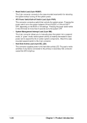
... to the hard disk activity LED. Pressing the power switch turns the system between ON and SLEEP, or ON and SOFT OFF, depending on the BIOS or OS settings. Pressing the power switch while in the ON mode for rebooting the system without turning off the system power. • ATX Power...
... to the hard disk activity LED. Pressing the power switch turns the system between ON and SLEEP, or ON and SOFT OFF, depending on the BIOS or OS settings. Pressing the power switch while in the ON mode for rebooting the system without turning off the system power. • ATX Power...


