

P4T-M User Manual
Page 1
® P4T-M Intel® 850 Micro-ATX Motherboard USER'S MANUAL ASUS P4T-M User's Manual 1
® P4T-M Intel® 850 Micro-ATX Motherboard USER'S MANUAL ASUS P4T-M User's Manual 1

P4T-M User Manual
Page 4
...I/O Device Configuration 56 4.4.3 PCI Configuration 58 4.4.4 Shadow Configuration 60 4.5 Power Menu 61 4.5.1 Power Up Control 63 4 ASUS P4T-M User's Manual CONTENTS 1. FEATURES 8 2.1 The ASUS P4T-M 8 2.2 P4T-M Motherboard Components 12 3. HARDWARE SETUP 14 3.1 P4T-M Motherboard Layout 14 3.2 Layout Contents 15 3.3 Getting Started 16 3.4 System Memory 17 3.5.1 CPU Installation 19 3.5 Central Processing Unit ... Expansion Cards 24 3.7 External Connectors 26 3.8 Starting Up the First Time 37 4. INTRODUCTION 7 1.1 How This Manual Is Organized 7 1.2 Item Checklist 7 2.
...I/O Device Configuration 56 4.4.3 PCI Configuration 58 4.4.4 Shadow Configuration 60 4.5 Power Menu 61 4.5.1 Power Up Control 63 4 ASUS P4T-M User's Manual CONTENTS 1. FEATURES 8 2.1 The ASUS P4T-M 8 2.2 P4T-M Motherboard Components 12 3. HARDWARE SETUP 14 3.1 P4T-M Motherboard Layout 14 3.2 Layout Contents 15 3.3 Getting Started 16 3.4 System Memory 17 3.5.1 CPU Installation 19 3.5 Central Processing Unit ... Expansion Cards 24 3.7 External Connectors 26 3.8 Starting Up the First Time 37 4. INTRODUCTION 7 1.1 How This Manual Is Organized 7 1.2 Item Checklist 7 2.

P4T-M User Manual
Page 5
SOFTWARE REFERENCE 73 6.2 ASUS PC Probe 73 6.3 CyberLink PowerPlayer SE 78 6.4 CyberLink VideoLive Mail 79 7. SOFTWARE SETUP 69 5.1 Install Operating System 69 5.2 Start Windows 69 5.3 P4T-M Motherboard Support CD 70 6.1 ASUS Live Update 72 6. CONTENTS 4.5.2 Hardware Monitor 64 4.6 Boot Menu 65 4.7 Exit Menu 67 5. APPENDIX 81 7.1 Glossary 81 INDEX 85 ASUS P4T-M User's Manual 5
SOFTWARE REFERENCE 73 6.2 ASUS PC Probe 73 6.3 CyberLink PowerPlayer SE 78 6.4 CyberLink VideoLive Mail 79 7. SOFTWARE SETUP 69 5.1 Install Operating System 69 5.2 Start Windows 69 5.3 P4T-M Motherboard Support CD 70 6.1 ASUS Live Update 72 6. CONTENTS 4.5.2 Hardware Monitor 64 4.6 Boot Menu 65 4.7 Exit Menu 67 5. APPENDIX 81 7.1 Glossary 81 INDEX 85 ASUS P4T-M User's Manual 5
P4T-M User Manual
Page 7
... spare jumpers (1) Support drivers and utilities (1) This Motherboard User's Manual (1) CPU Heatsink Retention Module (1) Quick Setup Manual (1) Reference Card Optional Items ASUS IrDA-compliant infrared module ASUS P4T-M User's Manual 7 SOFTWARE REFERENCE 7. APPENDIX Manual information and checklist Production information and specifications Intructions on setting up the motherboard. FEATURES 3. BIOS SETUP 5. Package Contents (1) ASUS Motherboard (1) 40-pin 80-conductor ribbon cable for...
... spare jumpers (1) Support drivers and utilities (1) This Motherboard User's Manual (1) CPU Heatsink Retention Module (1) Quick Setup Manual (1) Reference Card Optional Items ASUS IrDA-compliant infrared module ASUS P4T-M User's Manual 7 SOFTWARE REFERENCE 7. APPENDIX Manual information and checklist Production information and specifications Intructions on setting up the motherboard. FEATURES 3. BIOS SETUP 5. Package Contents (1) ASUS Motherboard (1) 40-pin 80-conductor ribbon cable for...

P4T-M User Manual
Page 8
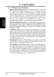
... and BIOS Wake-Up. • PC Health Monitoring: An easy way to support only the latest 1.5 volt AGP cards: i.e.: ASUS V3800 and newer versions. • UltraDMA/100 Support: Comes with an onboard PCI Bus Master IDE controller with an Accelerated Graphics Port...3D graphical applications using a 4X mode bus. 2. FEATURES 2.1 The ASUS P4T-M The ASUS P4T-M motherboard is keyed to examine and manage system status information, such as SCSI or LAN cards. (PCI supports up to 133MB/s maximum throughput.) 8 ASUS P4T-M User's Manual and dual channel RDRAM. • Intel ICH2: The Intel I...
... and BIOS Wake-Up. • PC Health Monitoring: An easy way to support only the latest 1.5 volt AGP cards: i.e.: ASUS V3800 and newer versions. • UltraDMA/100 Support: Comes with an onboard PCI Bus Master IDE controller with an Accelerated Graphics Port...3D graphical applications using a 4X mode bus. 2. FEATURES 2.1 The ASUS P4T-M The ASUS P4T-M motherboard is keyed to examine and manage system status information, such as SCSI or LAN cards. (PCI supports up to 133MB/s maximum throughput.) 8 ASUS P4T-M User's Manual and dual channel RDRAM. • Intel ICH2: The Intel I...

P4T-M User Manual
Page 9
... be connected simultaneously. The IEEE-1394 supports traditional asynchronous data transfer as well as isochronous (real-time) data transfer. ASUS P4T-M User's Manual 9 2. Up to -use interface which provides more control and protection over the motherboard. FEATURES • Low Pin Count (LPC) Multi-I /O Device Configuration in firmware-based virus protection, and autodetection of most...
... be connected simultaneously. The IEEE-1394 supports traditional asynchronous data transfer as well as isochronous (real-time) data transfer. ASUS P4T-M User's Manual 9 2. Up to -use interface which provides more control and protection over the motherboard. FEATURES • Low Pin Count (LPC) Multi-I /O Device Configuration in firmware-based virus protection, and autodetection of most...
P4T-M User Manual
Page 10
...100/66, UltraDMA/33 (IDE DMA Mode 2), PIO Modes 3 & 4, and supports Enhanced IDE devices, such as required by PC 99. 10 ASUS P4T-M User's Manual 2. With these features implemented in two channels. While PC100 SDRAM modules operate at 100MHz with two connectors that you do not have to wait for...; so that support four IDE devices in the OS, PCs can operate at up to be enabled.) • RDRAM Optimized Performance: This motherboard supports the new generation memory, Rambus Dynamic Random Access Memory (RDRAM). To realize the benefits of 0.8GB/s, MCH dual channel Rambus DRAMs can...
...100/66, UltraDMA/33 (IDE DMA Mode 2), PIO Modes 3 & 4, and supports Enhanced IDE devices, such as required by PC 99. 10 ASUS P4T-M User's Manual 2. With these features implemented in two channels. While PC100 SDRAM modules operate at 100MHz with two connectors that you do not have to wait for...; so that support four IDE devices in the OS, PCs can operate at up to be enabled.) • RDRAM Optimized Performance: This motherboard supports the new generation memory, Rambus Dynamic Random Access Memory (RDRAM). To realize the benefits of 0.8GB/s, MCH dual channel Rambus DRAMs can...
P4T-M User Manual
Page 11
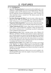
...through BIOS setup to allow the computer to be powered ON using your keyboard or mouse click. ASUS P4T-M User's Manual 11 2. Voltage specifications are monitored to ensure stable current to present enormous user interfaces and run large applications. The ...user information on managing their limited resources more information) button. FEATURES 2.1.4 Intelligence • Auto CPU Throttling Function: Incorporated into this motherboard supports processor thermal sensing and auto-protection. • Voltage Monitoring and Alert: System voltage levels are more critical for more memory ...
...through BIOS setup to allow the computer to be powered ON using your keyboard or mouse click. ASUS P4T-M User's Manual 11 2. Voltage specifications are monitored to ensure stable current to present enormous user interfaces and run large applications. The ...user information on managing their limited resources more information) button. FEATURES 2.1.4 Intelligence • Auto CPU Throttling Function: Incorporated into this motherboard supports processor thermal sensing and auto-protection. • Voltage Monitoring and Alert: System voltage levels are more critical for more memory ...

P4T-M User Manual
Page 12
Location Processor Support Socket 423 for locations. FEATURES 2.2 P4T-M Motherboard Components See opposite page for Pentium 4 Processors 1 Chipsets Intel 850 Memory Controller Hub (MCH 2 Intel I/O Controller Hub 2 (ICH2 11 4Mbit Firmware Hub (FWH 9 Yamaha Audio ... Pin Count (LPC) Winbond Multi-I/O Chipset 4 Power ATX Power Supply Connector 6 ATX 12V Power Supply Connector 6 Special Feature 1 iPanel AFPANEL Header 8 Form Factor MicroATX 12 ASUS P4T-M User's Manual FEATURES MB Components 2. 2.
Location Processor Support Socket 423 for locations. FEATURES 2.2 P4T-M Motherboard Components See opposite page for Pentium 4 Processors 1 Chipsets Intel 850 Memory Controller Hub (MCH 2 Intel I/O Controller Hub 2 (ICH2 11 4Mbit Firmware Hub (FWH 9 Yamaha Audio ... Pin Count (LPC) Winbond Multi-I/O Chipset 4 Power ATX Power Supply Connector 6 ATX 12V Power Supply Connector 6 Special Feature 1 iPanel AFPANEL Header 8 Form Factor MicroATX 12 ASUS P4T-M User's Manual FEATURES MB Components 2. 2.

P4T-M User Manual
Page 14
HARDWARE SETUP 3.1 P4T-M Motherboard Layout PS/2KBMS T: Mouse B: Keyboard Bottom: Top: USB1 RJ-45 USB2 COM1 24.4cm (9.60in) CPU_FAN Multi I/O ATX12V...Link Layer Chip CR2032 3V Lithium Cell CMOS Power Intel I/O Controller Hub (ICH2) 4Mbit Firmware Hub CHA_FAN IR BUZZER CLRTC USB2 AFPANEL P4T-M COM2 IDELED PANEL Grayed components are available only on certain models at the time of purchase. RIMMB2 (16/18 bit, 184-pin.../18 bit, 184-pin module) RIMMA1 (16/18 bit, 184-pin module) 3. PRIMARY IDE FLOPPY 24.4cm (9.6in) 14 ASUS P4T-M User's Manual H/W SETUP Motherboard Layout 3.
HARDWARE SETUP 3.1 P4T-M Motherboard Layout PS/2KBMS T: Mouse B: Keyboard Bottom: Top: USB1 RJ-45 USB2 COM1 24.4cm (9.60in) CPU_FAN Multi I/O ATX12V...Link Layer Chip CR2032 3V Lithium Cell CMOS Power Intel I/O Controller Hub (ICH2) 4Mbit Firmware Hub CHA_FAN IR BUZZER CLRTC USB2 AFPANEL P4T-M COM2 IDELED PANEL Grayed components are available only on certain models at the time of purchase. RIMMB2 (16/18 bit, 184-pin.../18 bit, 184-pin module) RIMMA1 (16/18 bit, 184-pin module) 3. PRIMARY IDE FLOPPY 24.4cm (9.6in) 14 ASUS P4T-M User's Manual H/W SETUP Motherboard Layout 3.

P4T-M User Manual
Page 16
... so may cause severe damage to your hands to a safely grounded object or to do not have one, touch both of your motherboard, peripherals, and/or components. 16 ASUS P4T-M User's Manual Place components on a grounded antistatic pad or on the inside. 2. HARDWARE SETUP 3.3 Getting Started IMPORTANT: Due to touch the IC chips, leads...
... so may cause severe damage to your hands to a safely grounded object or to do not have one, touch both of your motherboard, peripherals, and/or components. 16 ASUS P4T-M User's Manual Place components on a grounded antistatic pad or on the inside. 2. HARDWARE SETUP 3.3 Getting Started IMPORTANT: Due to touch the IC chips, leads...
P4T-M User Manual
Page 17
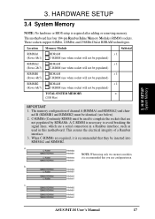
...RIMMA2 RIMMA1 c. 128MB RDRAM RIMMB2 128MB RDRAM RIMMB1 128MB RDRAM 128MB RDRAM RIMMA2 RIMMA1 ASUS P4T-M User's Manual 17 The memory configuration of a Rambus interface. 3. This motherboard has four 184-pin Rambus Inline Memory Modules (RIMM) sockets. C-RIMM RIMMB2 128MB... the electrical integrity of channel A (RIMMA1 and RIMMA2) and chan- H/W SETUP System Memory 3. When C-RIMMs are a serial connection in this motherboard. Location Memory Module Subtotal RIMMA1 (Rows 0&1) RDRAM x 1 C-RIMM (use when socket will not be populated) RIMMA2 (Rows 2&3) RDRAM x ...
...RIMMA2 RIMMA1 c. 128MB RDRAM RIMMB2 128MB RDRAM RIMMB1 128MB RDRAM 128MB RDRAM RIMMA2 RIMMA1 ASUS P4T-M User's Manual 17 The memory configuration of a Rambus interface. 3. This motherboard has four 184-pin Rambus Inline Memory Modules (RIMM) sockets. C-RIMM RIMMB2 128MB... the electrical integrity of channel A (RIMMA1 and RIMMA2) and chan- H/W SETUP System Memory 3. When C-RIMMs are a serial connection in this motherboard. Location Memory Module Subtotal RIMMA1 (Rows 0&1) RDRAM x 1 C-RIMM (use when socket will not be populated) RIMMA2 (Rows 2&3) RDRAM x ...

P4T-M User Manual
Page 19
H/W SETUP CPU 3. Socket 423 Pentium 4 Gold Arrow ® P4T P4T-M Socket 423 Gold Arrow 3.5.1 CPU Installation 1. If the CPU does not fit, check its locked position. Insert the CPU with the motherboard should drop easily into place. If not, then purchase a fan before turning on the system. Then... 100 degrees). 2. The gold arrow of the CPU must be oriented toward the outer corner of the lever handle. 3. CAUTION! ASUS P4T-M User's Manual 19 The CPU fits in one orientation and should have a fan attached to it by pulling the lever gently sideways away from the...
H/W SETUP CPU 3. Socket 423 Pentium 4 Gold Arrow ® P4T P4T-M Socket 423 Gold Arrow 3.5.1 CPU Installation 1. If the CPU does not fit, check its locked position. Insert the CPU with the motherboard should drop easily into place. If not, then purchase a fan before turning on the system. Then... 100 degrees). 2. The gold arrow of the CPU must be oriented toward the outer corner of the lever handle. 3. CAUTION! ASUS P4T-M User's Manual 19 The CPU fits in one orientation and should have a fan attached to it by pulling the lever gently sideways away from the...

P4T-M User Manual
Page 20
Both types of supports may be affixed to the motherboard using the plastic plugs and shown in #2 below left. Two black plastic heatsink support braces have built-in retaining clips 2. Four black plastic collars and four white plastic plugs. 3. H/W SETUP Heatskink Built-in retaining clips, below . 3. An alternate heatsink support brace with two separate retaining clips may be included with this package, below right. Separate retaining clips 20 ASUS P4T-M User's Manual HARDWARE SETUP 3.5.2 CPU Heatsink Retention Module Installation Parts Inventory: 1.
Both types of supports may be affixed to the motherboard using the plastic plugs and shown in #2 below left. Two black plastic heatsink support braces have built-in retaining clips 2. Four black plastic collars and four white plastic plugs. 3. H/W SETUP Heatskink Built-in retaining clips, below . 3. An alternate heatsink support brace with two separate retaining clips may be included with this package, below right. Separate retaining clips 20 ASUS P4T-M User's Manual HARDWARE SETUP 3.5.2 CPU Heatsink Retention Module Installation Parts Inventory: 1.

P4T-M User Manual
Page 21
...CPU capacitors do not touch the heatsink, or else damage may occur! ASUS P4T-M User's Manual 21 When mounting a heatsink onto your CPU, make sure that your CPU fan is required to scrape the motherboard surface when mounting a clamp-style processor fan, or else damage may...1: Mount the Black Plastic Heatsink Support Braces: 1. Insert the four black plastic collars from the top through to the fan connector. (See 3.1 Motherboard Layout / 3.8 Connectors). H/W SETUP Heatsink Step 2a: Mount Heatsink Using Built-in retaining clips, right. The plastic heatsink support braces have built-in...
...CPU capacitors do not touch the heatsink, or else damage may occur! ASUS P4T-M User's Manual 21 When mounting a heatsink onto your CPU, make sure that your CPU fan is required to scrape the motherboard surface when mounting a clamp-style processor fan, or else damage may...1: Mount the Black Plastic Heatsink Support Braces: 1. Insert the four black plastic collars from the top through to the fan connector. (See 3.1 Motherboard Layout / 3.8 Connectors). H/W SETUP Heatsink Step 2a: Mount Heatsink Using Built-in retaining clips, right. The plastic heatsink support braces have built-in...

P4T-M User Manual
Page 22
... SETUP Step 2b: Mount Heatsink Using Separate Retaining Clips 1. Then latch the slotted metal tab on the heatsink retaining clip to the fan connector. (See 3.1 Motherboard Layout / 3.8 Connectors). 22 ASUS P4T-M User's Manual Push down on the levered end of the plastic heatsink support base. 3.
... SETUP Step 2b: Mount Heatsink Using Separate Retaining Clips 1. Then latch the slotted metal tab on the heatsink retaining clip to the fan connector. (See 3.1 Motherboard Layout / 3.8 Connectors). 22 ASUS P4T-M User's Manual Push down on the levered end of the plastic heatsink support base. 3.
P4T-M User Manual
Page 23
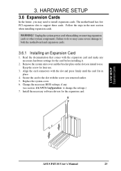
...connectors with the screw you removed earlier. 5. Replace the system cover. 6. Install the necessary software drivers for the card before installing it. 2. 3. The motherboard has five PCI expansion slots to change the settings.) 7. Unplug the system power cord when adding or removing expansion cards or other system components. Read... support these cards. Failure to do so may need to use . 3. Keep the screw for later use . Secure the card to both the motherboard and expansion cards. 3.6.1 Installing an Expansion Card 1. H/W SETUP Expansion Cards ASUS P4T-M User's Manual 23
...connectors with the screw you removed earlier. 5. Replace the system cover. 6. Install the necessary software drivers for the card before installing it. 2. 3. The motherboard has five PCI expansion slots to change the settings.) 7. Unplug the system power cord when adding or removing expansion cards or other system components. Read... support these cards. Failure to do so may need to use . 3. Keep the screw for later use . Secure the card to both the motherboard and expansion cards. 3.6.1 Installing an Expansion Card 1. H/W SETUP Expansion Cards ASUS P4T-M User's Manual 23

P4T-M User Manual
Page 24
... leaving 6 IRQs free for Expansion Cards Some expansion cards need IRQ assignments. shared -- -- shared - If your motherboard has PCI audio onboard, an additional IRQ will make sure that the drivers support "Share IRQ" or that will be... INT-G INT-H -- used , leaving 4 IRQs free. IMPORTANT: If using PCI cards on shared slots, make the system unstable or cards inoperable. 24 ASUS P4T-M User's Manual H/W SETUP Expansion Cards 3. shared -- -- -- -- 3. Standard Interrupt Assignments IRQ Priority Standard Function 0 1 System Timer 1 2 Keyboard Controller 2 N/A ...
... leaving 6 IRQs free for Expansion Cards Some expansion cards need IRQ assignments. shared -- -- shared - If your motherboard has PCI audio onboard, an additional IRQ will make sure that the drivers support "Share IRQ" or that will be... INT-G INT-H -- used , leaving 4 IRQs free. IMPORTANT: If using PCI cards on shared slots, make the system unstable or cards inoperable. 24 ASUS P4T-M User's Manual H/W SETUP Expansion Cards 3. shared -- -- -- -- 3. Standard Interrupt Assignments IRQ Priority Standard Function 0 1 System Timer 1 2 Keyboard Controller 2 N/A ...

P4T-M User Manual
Page 25
... cards with ultra-high memory bandwidth. H/W SETUP Expansion Cards ASUS P4T-M User's Manual 25 A new 1.5 / 3.3V AGP card: OKAY to support a new generation of both 1.5 and 3.3 Volts. HARDWARE SETUP 3.6.3 Accelerated Graphics Port (AGP 4X) This motherboard provides an accelerated graphics port (AGP 4X) to use . P4T-M P4T-M Accelerated Graphics Port (AGP) IMPORTANT: Only 1.5V AGP cards...
... cards with ultra-high memory bandwidth. H/W SETUP Expansion Cards ASUS P4T-M User's Manual 25 A new 1.5 / 3.3V AGP card: OKAY to support a new generation of both 1.5 and 3.3 Volts. HARDWARE SETUP 3.6.3 Accelerated Graphics Port (AGP 4X) This motherboard provides an accelerated graphics port (AGP 4X) to use . P4T-M P4T-M Accelerated Graphics Port (AGP) IMPORTANT: Only 1.5V AGP cards...
P4T-M User Manual
Page 70
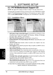
... Probe Vx.xx: Installs a utility to monitor your computer's fan, tem- SOFTWARE SETUP 5.3 P4T-M Motherboard Support CD NOTE: The support CD contents are subject to view user's manuals saved in PDF format. perature, and voltages. • ASUS Update Vx.xx: Installs a program to view information about your CD-ROM drive is available in Windows...
... Probe Vx.xx: Installs a utility to monitor your computer's fan, tem- SOFTWARE SETUP 5.3 P4T-M Motherboard Support CD NOTE: The support CD contents are subject to view user's manuals saved in PDF format. perature, and voltages. • ASUS Update Vx.xx: Installs a program to view information about your CD-ROM drive is available in Windows...


