

P4T-M User Manual
Page 1
® P4T-M Intel® 850 Micro-ATX Motherboard USER'S MANUAL ASUS P4T-M User's Manual 1
® P4T-M Intel® 850 Micro-ATX Motherboard USER'S MANUAL ASUS P4T-M User's Manual 1
P4T-M User Manual
Page 2
... DESCRIBED IN IT. Copyright © 2001 ASUSTeK COMPUTER INC. All Rights Reserved. Product Name: ASUS P4T-M Manual Revision: 1.04 E865 Release Date: September 2001 2 ASUS P4T-M User's Manual Manual revisions are both printed on the following page. SPECIFICATIONS AND INFORMATION CONTAINED IN THIS MANUAL ARE FURNISHED FOR INFORMATIONAL USE ONLY, AND ARE SUBJECT TO CHANGE AT ANY TIME...
... DESCRIBED IN IT. Copyright © 2001 ASUSTeK COMPUTER INC. All Rights Reserved. Product Name: ASUS P4T-M Manual Revision: 1.04 E865 Release Date: September 2001 2 ASUS P4T-M User's Manual Manual revisions are both printed on the following page. SPECIFICATIONS AND INFORMATION CONTAINED IN THIS MANUAL ARE FURNISHED FOR INFORMATIONAL USE ONLY, AND ARE SUBJECT TO CHANGE AT ANY TIME...

P4T-M User Manual
Page 3
...) Notebook (Tel): +886-2-2890-7122 (English) Desktop/Server (Tel):+886-2-2890-7123 (English) Fax: +886-2-2890-7698 Email: tsd@asus.com.tw WWW: www.asus.com.tw FTP: ftp.asus.com.tw/pub/ASUS ASUS COMPUTER INTERNATIONAL (America) Marketing Address: 6737 Mowry Avenue, Mowry Business Center, Building 2 Newark, CA 94560, USA Fax: +1-510-608-4555... Fax: +49-2102-9599-11 Support (Email): www.asuscom.de/de/support (for online support) WWW: www.asuscom.de FTP: ftp.asuscom.de/pub/ASUSCOM ASUS P4T-M User's Manual 3
...) Notebook (Tel): +886-2-2890-7122 (English) Desktop/Server (Tel):+886-2-2890-7123 (English) Fax: +886-2-2890-7698 Email: tsd@asus.com.tw WWW: www.asus.com.tw FTP: ftp.asus.com.tw/pub/ASUS ASUS COMPUTER INTERNATIONAL (America) Marketing Address: 6737 Mowry Avenue, Mowry Business Center, Building 2 Newark, CA 94560, USA Fax: +1-510-608-4555... Fax: +49-2102-9599-11 Support (Email): www.asuscom.de/de/support (for online support) WWW: www.asuscom.de FTP: ftp.asuscom.de/pub/ASUSCOM ASUS P4T-M User's Manual 3

P4T-M User Manual
Page 4
... Expansion Card 23 3.6.2 Assigning IRQs for Expansion Cards 24 3.7 External Connectors 26 3.8 Starting Up the First Time 37 4. FEATURES 8 2.1 The ASUS P4T-M 8 2.2 P4T-M Motherboard Components 12 3. BIOS SETUP 39 4.1 Managing and Updating Your BIOS 39 4.1.1 Upon First Use of the Computer System 39 4.1.2 Updating BIOS... 54 4.4.2 I/O Device Configuration 56 4.4.3 PCI Configuration 58 4.4.4 Shadow Configuration 60 4.5 Power Menu 61 4.5.1 Power Up Control 63 4 ASUS P4T-M User's Manual CONTENTS 1. INTRODUCTION 7 1.1 How This Manual Is Organized 7 1.2 Item Checklist 7 2.
... Expansion Card 23 3.6.2 Assigning IRQs for Expansion Cards 24 3.7 External Connectors 26 3.8 Starting Up the First Time 37 4. FEATURES 8 2.1 The ASUS P4T-M 8 2.2 P4T-M Motherboard Components 12 3. BIOS SETUP 39 4.1 Managing and Updating Your BIOS 39 4.1.1 Upon First Use of the Computer System 39 4.1.2 Updating BIOS... 54 4.4.2 I/O Device Configuration 56 4.4.3 PCI Configuration 58 4.4.4 Shadow Configuration 60 4.5 Power Menu 61 4.5.1 Power Up Control 63 4 ASUS P4T-M User's Manual CONTENTS 1. INTRODUCTION 7 1.1 How This Manual Is Organized 7 1.2 Item Checklist 7 2.

P4T-M User Manual
Page 5
CONTENTS 4.5.2 Hardware Monitor 64 4.6 Boot Menu 65 4.7 Exit Menu 67 5. SOFTWARE SETUP 69 5.1 Install Operating System 69 5.2 Start Windows 69 5.3 P4T-M Motherboard Support CD 70 6.1 ASUS Live Update 72 6. SOFTWARE REFERENCE 73 6.2 ASUS PC Probe 73 6.3 CyberLink PowerPlayer SE 78 6.4 CyberLink VideoLive Mail 79 7. APPENDIX 81 7.1 Glossary 81 INDEX 85 ASUS P4T-M User's Manual 5
CONTENTS 4.5.2 Hardware Monitor 64 4.6 Boot Menu 65 4.7 Exit Menu 67 5. SOFTWARE SETUP 69 5.1 Install Operating System 69 5.2 Start Windows 69 5.3 P4T-M Motherboard Support CD 70 6.1 ASUS Live Update 72 6. SOFTWARE REFERENCE 73 6.2 ASUS PC Probe 73 6.3 CyberLink PowerPlayer SE 78 6.4 CyberLink VideoLive Mail 79 7. APPENDIX 81 7.1 Glossary 81 INDEX 85 ASUS P4T-M User's Manual 5

P4T-M User Manual
Page 6
... the Canadian Department of the FCC Rules. Cet appareil numérique de la classe B est conforme à la norme NMB-003 du Canada. 6 ASUS P4T-M User's Manual Operation is no guarantee that may cause harmful interference to the following measures: • Re-orient or relocate the receiving antenna. • Increase the separation...
... the Canadian Department of the FCC Rules. Cet appareil numérique de la classe B est conforme à la norme NMB-003 du Canada. 6 ASUS P4T-M User's Manual Operation is no guarantee that may cause harmful interference to the following measures: • Re-orient or relocate the receiving antenna. • Increase the separation...
P4T-M User Manual
Page 7
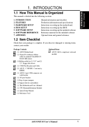
... USB connector set with bracket (1) I/O port bracket (1) Bag of spare jumpers (1) Support drivers and utilities (1) This Motherboard User's Manual (1) CPU Heatsink Retention Module (1) Quick Setup Manual (1) Reference Card Optional Items ASUS IrDA-compliant infrared module ASUS P4T-M User's Manual 7 If you discover damaged or missing items, contact your package is divided into the following sections: 1. INTRODUCTION...
... USB connector set with bracket (1) I/O port bracket (1) Bag of spare jumpers (1) Support drivers and utilities (1) This Motherboard User's Manual (1) CPU Heatsink Retention Module (1) Quick Setup Manual (1) Reference Card Optional Items ASUS IrDA-compliant infrared module ASUS P4T-M User's Manual 7 If you discover damaged or missing items, contact your package is divided into the following sections: 1. INTRODUCTION...

P4T-M User Manual
Page 8
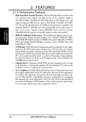
... AGP cards for UltraDMA/100, which allows burst mode data transfer rates of up to 133MB/s maximum throughput.) 8 ASUS P4T-M User's Manual FEATURES 2.1 The ASUS P4T-M The ASUS P4T-M motherboard is carefully designed for the demanding PC user who wants advanced features processed by the fastest processors. 2.1.1 Specifications...status information, such as SCSI or LAN cards. (PCI supports up to support only the latest 1.5 volt AGP cards: i.e.: ASUS V3800 and newer versions. • UltraDMA/100 Support: Comes with an onboard PCI Bus Master IDE controller with no ISA, eliminating...
... AGP cards for UltraDMA/100, which allows burst mode data transfer rates of up to 133MB/s maximum throughput.) 8 ASUS P4T-M User's Manual FEATURES 2.1 The ASUS P4T-M The ASUS P4T-M motherboard is carefully designed for the demanding PC user who wants advanced features processed by the fastest processors. 2.1.1 Specifications...status information, such as SCSI or LAN cards. (PCI supports up to support only the latest 1.5 volt AGP cards: i.e.: ASUS V3800 and newer versions. • UltraDMA/100 Support: Comes with an onboard PCI Bus Master IDE controller with no ISA, eliminating...

P4T-M User Manual
Page 9
... intensive consumer electronics devices like: DV camcorders, digital cameras, scanners, and printers. Up to -use interface which provides more control and protection over the motherboard. ASUS P4T-M User's Manual 9 UART2 can also be connected simultaneously. 2.
... intensive consumer electronics devices like: DV camcorders, digital cameras, scanners, and printers. Up to -use interface which provides more control and protection over the motherboard. ASUS P4T-M User's Manual 9 UART2 can also be connected simultaneously. 2.
P4T-M User Manual
Page 10
Supports UltraDMA/100/66, UltraDMA/33 (IDE DMA Mode 2), PIO Modes 3 & 4, and supports Enhanced IDE devices, such as required by PC 99. 10 ASUS P4T-M User's Manual Color-coded connectors and descriptive icons make identification easy as DVD-ROM, CD-ROM, CD-R/RW, LS-120, and Tape Backup drives. ACPI provides more ...
Supports UltraDMA/100/66, UltraDMA/33 (IDE DMA Mode 2), PIO Modes 3 & 4, and supports Enhanced IDE devices, such as required by PC 99. 10 ASUS P4T-M User's Manual Color-coded connectors and descriptive icons make identification easy as DVD-ROM, CD-ROM, CD-R/RW, LS-120, and Tape Backup drives. ACPI provides more ...
P4T-M User Manual
Page 11
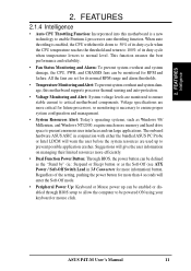
...% of the setting, pushing the power button for RPM and failure. When auto throttling is enabled, the CPU with either the bundled ASUS PC Probe or Intel LDCM will warn the user before the system resources are set for its normal RPM range and alarm thresholds. •... in 3.8 Connectors for future processors, so monitoring is a new technology to present enormous user interfaces and run large applications. ASUS P4T-M User's Manual 11 This function ensures the best performance and reliability. • Fan Status Monitoring and Alarm: To prevent system overheat and system damage, ...
...% of the setting, pushing the power button for RPM and failure. When auto throttling is enabled, the CPU with either the bundled ASUS PC Probe or Intel LDCM will warn the user before the system resources are set for its normal RPM range and alarm thresholds. •... in 3.8 Connectors for future processors, so monitoring is a new technology to present enormous user interfaces and run large applications. ASUS P4T-M User's Manual 11 This function ensures the best performance and reliability. • Fan Status Monitoring and Alarm: To prevent system overheat and system damage, ...

P4T-M User Manual
Page 12
FEATURES MB Components 2. Location Processor Support Socket 423 for locations. 2. FEATURES 2.2 P4T-M Motherboard Components See opposite page for Pentium 4 Processors 1 Chipsets Intel 850 Memory Controller Hub (MCH 2 Intel I/O Controller Hub 2 (ICH2 11 4Mbit Firmware Hub (FWH 9 Yamaha ... Pin Count (LPC) Winbond Multi-I/O Chipset 4 Power ATX Power Supply Connector 6 ATX 12V Power Supply Connector 6 Special Feature 1 iPanel AFPANEL Header 8 Form Factor MicroATX 12 ASUS P4T-M User's Manual
FEATURES MB Components 2. Location Processor Support Socket 423 for locations. 2. FEATURES 2.2 P4T-M Motherboard Components See opposite page for Pentium 4 Processors 1 Chipsets Intel 850 Memory Controller Hub (MCH 2 Intel I/O Controller Hub 2 (ICH2 11 4Mbit Firmware Hub (FWH 9 Yamaha ... Pin Count (LPC) Winbond Multi-I/O Chipset 4 Power ATX Power Supply Connector 6 ATX 12V Power Supply Connector 6 Special Feature 1 iPanel AFPANEL Header 8 Form Factor MicroATX 12 ASUS P4T-M User's Manual

P4T-M User Manual
Page 14
H/W SETUP Motherboard Layout 3. PRIMARY IDE FLOPPY 24.4cm (9.6in) 14 ASUS P4T-M User's Manual HARDWARE SETUP 3.1 P4T-M Motherboard Layout PS/2KBMS T: Mouse B: Keyboard Bottom: Top: USB1 RJ-45 USB2 COM1 24.4cm (9.60in) CPU_FAN Multi I/O ATX12V ATX Power Connector PARALLEL ...CD_IN PCI3 1394 Link Layer Chip CR2032 3V Lithium Cell CMOS Power Intel I/O Controller Hub (ICH2) 4Mbit Firmware Hub CHA_FAN IR BUZZER CLRTC USB2 AFPANEL P4T-M COM2 IDELED PANEL Grayed components are available only on certain models at the time of purchase. RIMMB2 (16/18 bit, 184-pin module) RIMMB1...
H/W SETUP Motherboard Layout 3. PRIMARY IDE FLOPPY 24.4cm (9.6in) 14 ASUS P4T-M User's Manual HARDWARE SETUP 3.1 P4T-M Motherboard Layout PS/2KBMS T: Mouse B: Keyboard Bottom: Top: USB1 RJ-45 USB2 COM1 24.4cm (9.60in) CPU_FAN Multi I/O ATX12V ATX Power Connector PARALLEL ...CD_IN PCI3 1394 Link Layer Chip CR2032 3V Lithium Cell CMOS Power Intel I/O Controller Hub (ICH2) 4Mbit Firmware Hub CHA_FAN IR BUZZER CLRTC USB2 AFPANEL P4T-M COM2 IDELED PANEL Grayed components are available only on certain models at the time of purchase. RIMMB2 (16/18 bit, 184-pin module) RIMMB1...

P4T-M User Manual
Page 15
... System Management Interrupt Switch Lead (2 pin) 27) PWRSW (PANEL) p.36 ATX Power / Soft-Off Switch Lead (2 pin) 28) RESET (PANEL) p.36 Reset Switch Lead (2 pin) ASUS P4T-M User's Manual 15 3.
... System Management Interrupt Switch Lead (2 pin) 27) PWRSW (PANEL) p.36 ATX Power / Soft-Off Switch Lead (2 pin) 28) RESET (PANEL) p.36 Reset Switch Lead (2 pin) ASUS P4T-M User's Manual 15 3.

P4T-M User Manual
Page 16
... severe damage to your hands to a safely grounded object or to do not have one, touch both of your motherboard, peripherals, and/or components. 16 ASUS P4T-M User's Manual If you must complete the following steps: • Check Motherboard Settings • Install Memory Modules • Install the Central Processing Unit (CPU) • Install...
... severe damage to your hands to a safely grounded object or to do not have one, touch both of your motherboard, peripherals, and/or components. 16 ASUS P4T-M User's Manual If you must complete the following steps: • Check Motherboard Settings • Install Memory Modules • Install the Central Processing Unit (CPU) • Install...
P4T-M User Manual
Page 17
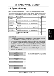
... a. 128MB RDRAM RIMMA1 b. 128MB RDRAM RIMMB2 C-RIMM RIMMB1 128MB RDRAM C-RIMM RIMMA2 RIMMA1 c. 128MB RDRAM RIMMB2 128MB RDRAM RIMMB1 128MB RDRAM 128MB RDRAM RIMMA2 RIMMA1 ASUS P4T-M User's Manual 17
... a. 128MB RDRAM RIMMA1 b. 128MB RDRAM RIMMB2 C-RIMM RIMMB1 128MB RDRAM C-RIMM RIMMA2 RIMMA1 c. 128MB RDRAM RIMMB2 128MB RDRAM RIMMB1 128MB RDRAM 128MB RDRAM RIMMA2 RIMMA1 ASUS P4T-M User's Manual 17

P4T-M User Manual
Page 18
...! The guides on the socket's ejectors should go through the two mounting notches on the memory module until it snaps into place. H/W SETUP System Memory P4T-M P4T-M 184-Pin RIMM Sockets 1. Make sure that the notch keys in the open position (as shown), push down gently but firmly on the module and.../C-RIMM) will fit in place. RIMM modules become extremely hot during operation. If necessary, push the ejectors inward to cool off before removing them. 18 ASUS P4T-M User's Manual
...! The guides on the socket's ejectors should go through the two mounting notches on the memory module until it snaps into place. H/W SETUP System Memory P4T-M P4T-M 184-Pin RIMM Sockets 1. Make sure that the notch keys in the open position (as shown), push down gently but firmly on the module and.../C-RIMM) will fit in place. RIMM modules become extremely hot during operation. If necessary, push the ejectors inward to cool off before removing them. 18 ASUS P4T-M User's Manual

P4T-M User Manual
Page 19
... alignment and look for the P4 Socket 423 CPU. HARDWARE SETUP 3.5 Central Processing Unit (CPU) The motherboard provides a ZIF Socket for bent pins. CAUTION! ASUS P4T-M User's Manual 19 The CPU that came with the correct orientation. Once completely inserted, press the CPU firmly and close the socket lever until it by pulling... the CPU does not fit, check its locked position. If not, then purchase a fan before turning on the system. Socket 423 Pentium 4 Gold Arrow ® P4T P4T-M Socket 423 Gold Arrow 3.5.1 CPU Installation 1.
... alignment and look for the P4 Socket 423 CPU. HARDWARE SETUP 3.5 Central Processing Unit (CPU) The motherboard provides a ZIF Socket for bent pins. CAUTION! ASUS P4T-M User's Manual 19 The CPU that came with the correct orientation. Once completely inserted, press the CPU firmly and close the socket lever until it by pulling... the CPU does not fit, check its locked position. If not, then purchase a fan before turning on the system. Socket 423 Pentium 4 Gold Arrow ® P4T P4T-M Socket 423 Gold Arrow 3.5.1 CPU Installation 1.

P4T-M User Manual
Page 20
Both types of supports may be affixed to the motherboard using the plastic plugs and shown in #2 below left. Separate retaining clips 20 ASUS P4T-M User's Manual HARDWARE SETUP 3.5.2 CPU Heatsink Retention Module Installation Parts Inventory: 1. An alternate heatsink support brace with two separate retaining clips may be included with this package, below right. H/W SETUP Heatskink Built-in retaining clips, below . 3. 3. Four black plastic collars and four white plastic plugs. Two black plastic heatsink support braces have built-in retaining clips 2.
Both types of supports may be affixed to the motherboard using the plastic plugs and shown in #2 below left. Separate retaining clips 20 ASUS P4T-M User's Manual HARDWARE SETUP 3.5.2 CPU Heatsink Retention Module Installation Parts Inventory: 1. An alternate heatsink support brace with two separate retaining clips may be included with this package, below right. H/W SETUP Heatskink Built-in retaining clips, below . 3. 3. Four black plastic collars and four white plastic plugs. Two black plastic heatsink support braces have built-in retaining clips 2.

P4T-M User Manual
Page 21
... the motherboard. H/W SETUP Heatsink Step 2a: Mount Heatsink Using Built-in retaining clips, right. Take care not to both the processor and the motherboard. ASUS P4T-M User's Manual 21 Close and snap the clips into the middle of the black plastic collars and pop them firmly out the bottom of the motherboard. Without...
... the motherboard. H/W SETUP Heatsink Step 2a: Mount Heatsink Using Built-in retaining clips, right. Take care not to both the processor and the motherboard. ASUS P4T-M User's Manual 21 Close and snap the clips into the middle of the black plastic collars and pop them firmly out the bottom of the motherboard. Without...


