Motherboard DIY Troubleshooting Guide
Page 1
® P4T-CM Intel® 850 Micro-ATX Motherboard USER'S MANUAL ASUS P4T-CM User's Manual 1
® P4T-CM Intel® 850 Micro-ATX Motherboard USER'S MANUAL ASUS P4T-CM User's Manual 1
Motherboard DIY Troubleshooting Guide
Page 4
... CPU Heatsink Retention Module Installation 20 3.6 Expansion Cards 22 3.7 External Connectors 24 3.9 Starting Up the First Time 35 4. FEATURES 8 2.1 The ASUS P4T-CM 8 2.2 P4T-CM Motherboard Components 12 3. CONTENTS 1. BIOS SETUP 37 4.1 Managing and Updating Your BIOS 37 4.1.1 Upon First Use of the Computer System 37 4.1.2 Updating BIOS... 55 4.4.3 PCI Configuration 57 4.4.4 Shadow Configuration 59 4.5 Power Menu 60 4.5.1 Power Up Control 61 4.5.2 Hardware Monitor 62 4 ASUS P4T-CM User's Manual INTRODUCTION 7 1.1 How This Manual Is Organized 7 1.2 Item Checklist 7 2.
... CPU Heatsink Retention Module Installation 20 3.6 Expansion Cards 22 3.7 External Connectors 24 3.9 Starting Up the First Time 35 4. FEATURES 8 2.1 The ASUS P4T-CM 8 2.2 P4T-CM Motherboard Components 12 3. CONTENTS 1. BIOS SETUP 37 4.1 Managing and Updating Your BIOS 37 4.1.1 Upon First Use of the Computer System 37 4.1.2 Updating BIOS... 55 4.4.3 PCI Configuration 57 4.4.4 Shadow Configuration 59 4.5 Power Menu 60 4.5.1 Power Up Control 61 4.5.2 Hardware Monitor 62 4 ASUS P4T-CM User's Manual INTRODUCTION 7 1.1 How This Manual Is Organized 7 1.2 Item Checklist 7 2.
Motherboard DIY Troubleshooting Guide
Page 5
SOFTWARE REFERENCE 71 6.1 ASUS PC Probe 71 6.2 ASUS Live Update 76 6.4 CyberLink PowerPlayer SE 77 6.5 CyberLink VideoLive Mail 78 7. APPENDIX 81 7.1 Glossary 81 INDEX 85 ASUS P4T-CM User's Manual 5 SOFTWARE SETUP 67 5.1 Install Operating System 67 5.2 Start Windows 67 5.3 P4T-CM Motherboard Support CD 68 6. CONTENTS 4.6 Boot Menu 63 4.7 Exit Menu 65 5.
SOFTWARE REFERENCE 71 6.1 ASUS PC Probe 71 6.2 ASUS Live Update 76 6.4 CyberLink PowerPlayer SE 77 6.5 CyberLink VideoLive Mail 78 7. APPENDIX 81 7.1 Glossary 81 INDEX 85 ASUS P4T-CM User's Manual 5 SOFTWARE SETUP 67 5.1 Install Operating System 67 5.2 Start Windows 67 5.3 P4T-CM Motherboard Support CD 68 6. CONTENTS 4.6 Boot Menu 63 4.7 Exit Menu 65 5.

Motherboard DIY Troubleshooting Guide
Page 7
... with bracket (1) I/O port bracket (1) Bag of spare jumpers (1) Support drivers and utilities (1) This Motherboard User's Manual (1) CPU Retention Module (1) CD Audio Optional Items ASUS IrDA-compliant infrared module ASUS PCI-L101 Wake-On-LAN 10/ 1000 ethernet card ASUS P4T-CM User's Manual 7 Package Contents (1) ASUS Motherboard (1) 40-pin 80-conductor ribbon cable for internal UltraDMA33/ 66/100 IDE drives...
... with bracket (1) I/O port bracket (1) Bag of spare jumpers (1) Support drivers and utilities (1) This Motherboard User's Manual (1) CPU Retention Module (1) CD Audio Optional Items ASUS IrDA-compliant infrared module ASUS PCI-L101 Wake-On-LAN 10/ 1000 ethernet card ASUS P4T-CM User's Manual 7 Package Contents (1) ASUS Motherboard (1) 40-pin 80-conductor ribbon cable for internal UltraDMA33/ 66/100 IDE drives...
Motherboard DIY Troubleshooting Guide
Page 8
...ASUS P4T-CM The ASUS P4T-CM motherboard is required. • Intel® Accelerated Hub Architecture: Features a dedicated high speed hub link between the ICH2 and MCH with an Accelerated Graphics Port 4X slot that support four IDE devices on two channels. The slot is keyed to 133MB/s maximum throughput.) 8 ASUS P4T-CM User's Manual...and Enhanced IDE devices, such as CPU and systerm voltages, temperatures, and fan status through the onboard hardware and the bundled ASUS PC Probe or Intel LDCM software. • Legacy Free: Provides three 32-bit PCI (PCI 2.2 compliant) with two ...
...ASUS P4T-CM The ASUS P4T-CM motherboard is required. • Intel® Accelerated Hub Architecture: Features a dedicated high speed hub link between the ICH2 and MCH with an Accelerated Graphics Port 4X slot that support four IDE devices on two channels. The slot is keyed to 133MB/s maximum throughput.) 8 ASUS P4T-CM User's Manual...and Enhanced IDE devices, such as CPU and systerm voltages, temperatures, and fan status through the onboard hardware and the bundled ASUS PC Probe or Intel LDCM software. • Legacy Free: Provides three 32-bit PCI (PCI 2.2 compliant) with two ...

Motherboard DIY Troubleshooting Guide
Page 9
... Single chip fast ethernet controller for throughput intensive consumer electronics devices like: DV camcorders, digital cameras, scanners, and printers. ASUS P4T-CM User's Manual 9 Added featuers include 3D stereo enhancement, and extra true line-level out for the latest consumer electronics devices. •...isochronous (real-time) data transfer. The chipset supporst up to -use interface which provides more control and protection over the motherboard. FEATURES • Low Pin Count (LPC) Multi-I /O Device Configuration in firmware-based virus protection, and autodetection of most...
... Single chip fast ethernet controller for throughput intensive consumer electronics devices like: DV camcorders, digital cameras, scanners, and printers. ASUS P4T-CM User's Manual 9 Added featuers include 3D stereo enhancement, and extra true line-level out for the latest consumer electronics devices. •...isochronous (real-time) data transfer. The chipset supporst up to -use interface which provides more control and protection over the motherboard. FEATURES • Low Pin Count (LPC) Multi-I /O Device Configuration in firmware-based virus protection, and autodetection of most...

Motherboard DIY Troubleshooting Guide
Page 10
...support four IDE devices in the OS, PCs can operate at up to be enabled.) • RDRAM Optimized Performance: This motherboard supports the new generation memory, Rambus Dynamic Random Access Memory (RDRAM). While PC100 SDRAM modules operate at 100MHz with a peak bandwidth of...99 requirements for systems and components are based on all ASUS smart series motherboards. Supports UltraDMA/100/66, UltraDMA/33 (IDE DMA Mode 2), PIO Modes 3 & 4, and supports Enhanced IDE devices, such as required by PC 99. 10 ASUS P4T-CM User's Manual ACPI provides more Energy Saving Features for PC 99 ...
...support four IDE devices in the OS, PCs can operate at up to be enabled.) • RDRAM Optimized Performance: This motherboard supports the new generation memory, Rambus Dynamic Random Access Memory (RDRAM). While PC100 SDRAM modules operate at 100MHz with a peak bandwidth of...99 requirements for systems and components are based on all ASUS smart series motherboards. Supports UltraDMA/100/66, UltraDMA/33 (IDE DMA Mode 2), PIO Modes 3 & 4, and supports Enhanced IDE devices, such as required by PC 99. 10 ASUS P4T-CM User's Manual ACPI provides more Energy Saving Features for PC 99 ...
Motherboard DIY Troubleshooting Guide
Page 11
...Regardless of its normal RPM range and alarm thresholds. • Temperature Monitoring andAlert: To prevent system overheat and system damage, this motherboard is necessary to ensure proper system configuration and management. • System Resources Alert: Today's operating systems, such as Windows 98/... 50% of its duty cycle when the CPU temperature reaches the threshold and return to prevent possible application crashes. ASUS P4T-CM User's Manual 11 All the fans are monitored to ensure stable current to enable Pentium 4 processors auto throttling function. Suggestions will...
...Regardless of its normal RPM range and alarm thresholds. • Temperature Monitoring andAlert: To prevent system overheat and system damage, this motherboard is necessary to ensure proper system configuration and management. • System Resources Alert: Today's operating systems, such as Windows 98/... 50% of its duty cycle when the CPU temperature reaches the threshold and return to prevent possible application crashes. ASUS P4T-CM User's Manual 11 All the fans are monitored to ensure stable current to enable Pentium 4 processors auto throttling function. Suggestions will...
Motherboard DIY Troubleshooting Guide
Page 12
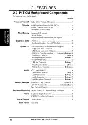
FEATURES MB Components 2. Location Processor Support Socket 423 for locations. FEATURES 2.2 P4T-CM Motherboard Components See opposite page for Pentium 4 Processors 1 Chipsets Intel 850 Memory Controller Hub (MCH 2 Intel I/O Controller Hub 2 (ICH2 11 4Mbit Firmware Hub (FWH 9 Main Memory ... Low Pin Count (LPC) Winbond Multi-I/O Chipset 4 Power ATX Power Supply Connector 6 ATX 12V Power Supply Connector 6 Special Feature 1 iPanel Header 8 Form Factor MicroATX 12 ASUS P4T-CM User's Manual 2.
FEATURES MB Components 2. Location Processor Support Socket 423 for locations. FEATURES 2.2 P4T-CM Motherboard Components See opposite page for Pentium 4 Processors 1 Chipsets Intel 850 Memory Controller Hub (MCH 2 Intel I/O Controller Hub 2 (ICH2 11 4Mbit Firmware Hub (FWH 9 Main Memory ... Low Pin Count (LPC) Winbond Multi-I/O Chipset 4 Power ATX Power Supply Connector 6 ATX 12V Power Supply Connector 6 Special Feature 1 iPanel Header 8 Form Factor MicroATX 12 ASUS P4T-CM User's Manual 2.
Motherboard DIY Troubleshooting Guide
Page 14
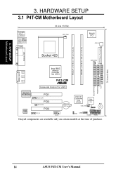
3. SECONDARY IDE PRIMARY IDE FLOPPY 24.4cm (9.6in) 14 ASUS P4T-CM User's Manual HARDWARE SETUP 3.1 P4T-CM Motherboard Layout PS/2KBMS T: Mouse B: Keyboard Bottom: Top: USB1 RJ-45 USB2 COM1 24.4cm (9.60in) CPU_FAN Multi I/O ATX12V ATX Power Connector RIMMA1 (16/18... module) RIMMB1 (16/18 bit, 184-pin module) PARALLEL PORT Socket 423 PWR_FAN GAME_AUDIO Intel 850 Memory Line Out Controller Hub (MCH) Line In Mic P4T-CM In ® Accelerated Graphics Port (AGP) 1 1 1 Realtek RTL8139C Audio Codec PCI1 AUX_CON PCI2 WOLCON PCI3 CD_IN CR2032 3V Lithium Cell CMOS Power COM2 ...
3. SECONDARY IDE PRIMARY IDE FLOPPY 24.4cm (9.6in) 14 ASUS P4T-CM User's Manual HARDWARE SETUP 3.1 P4T-CM Motherboard Layout PS/2KBMS T: Mouse B: Keyboard Bottom: Top: USB1 RJ-45 USB2 COM1 24.4cm (9.60in) CPU_FAN Multi I/O ATX12V ATX Power Connector RIMMA1 (16/18... module) RIMMB1 (16/18 bit, 184-pin module) PARALLEL PORT Socket 423 PWR_FAN GAME_AUDIO Intel 850 Memory Line Out Controller Hub (MCH) Line In Mic P4T-CM In ® Accelerated Graphics Port (AGP) 1 1 1 Realtek RTL8139C Audio Codec PCI1 AUX_CON PCI2 WOLCON PCI3 CD_IN CR2032 3V Lithium Cell CMOS Power COM2 ...

Motherboard DIY Troubleshooting Guide
Page 16
...touch both of your hands to a safely grounded object or to Pentium 4 CPU's power consumption requirement, an ATX12V power supply is required. Computer motherboards and expansion cards contain very delicate Integrated Circuit (IC) chips. H/W SETUP Getting Started 3. Unplug your computer. 1. Ensure that came with the... 3.3 Getting Started IMPORTANT: Due to a metal object, such as the power supply case. 3. Before using your computer, you unplug your motherboard, peripherals, and/or components. 16 ASUS P4T-CM User's Manual Use a grounded wrist strap before you work on the...
...touch both of your hands to a safely grounded object or to Pentium 4 CPU's power consumption requirement, an ATX12V power supply is required. Computer motherboards and expansion cards contain very delicate Integrated Circuit (IC) chips. H/W SETUP Getting Started 3. Unplug your computer. 1. Ensure that came with the... 3.3 Getting Started IMPORTANT: Due to a metal object, such as the power supply case. 3. Before using your computer, you unplug your motherboard, peripherals, and/or components. 16 ASUS P4T-CM User's Manual Use a grounded wrist strap before you work on the...
Motherboard DIY Troubleshooting Guide
Page 17
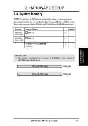
The memory configuration of channel A (RIMMA1 ) and channel B (RIMMB1) must be identical. 128MB RDRAM RIMMB1 128MB RDRAM RIMMA1 3. This motherboard has two 184-pin Rambus Inline Memory Modules (RIMM) sockets. These sockets support 64Mbit, 128Mbit, and 256Mbit Direct RDRAM technologies. Location Memory Module RIMMA1 (Rows 0&1) ... MEMORY (1GB Max) Subtotal x 1 x 1 = IMPORTANT 1. HARDWARE SETUP 3.4 System Memory NOTE: No hardware or BIOS setup is required after adding or removing memory. 3. H/W SETUP System Memory ASUS P4T-CM User's Manual 17
The memory configuration of channel A (RIMMA1 ) and channel B (RIMMB1) must be identical. 128MB RDRAM RIMMB1 128MB RDRAM RIMMA1 3. This motherboard has two 184-pin Rambus Inline Memory Modules (RIMM) sockets. These sockets support 64Mbit, 128Mbit, and 256Mbit Direct RDRAM technologies. Location Memory Module RIMMA1 (Rows 0&1) ... MEMORY (1GB Max) Subtotal x 1 x 1 = IMPORTANT 1. HARDWARE SETUP 3.4 System Memory NOTE: No hardware or BIOS setup is required after adding or removing memory. 3. H/W SETUP System Memory ASUS P4T-CM User's Manual 17
Motherboard DIY Troubleshooting Guide
Page 19
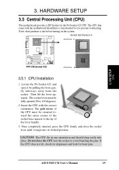
... Locate the P4 Socket 423 and open it to avoid bending the pins. Insert the CPU with the motherboard should drop easily into the socket to prevent overheating. CAUTION! ASUS P4T-CM User's Manual 19 Then lift the lever upwards. If the CPU does not fit, check its locked position. Once ... have a fan attached to it by pulling the lever gently sideways away from the socket. HARDWARE SETUP 3.5 Central Processing Unit (CPU) The motherboard provides a ZIF Socket for bent pins. The CPU that came with the correct orientation. Do not force the CPU into place. The socket...
... Locate the P4 Socket 423 and open it to avoid bending the pins. Insert the CPU with the motherboard should drop easily into the socket to prevent overheating. CAUTION! ASUS P4T-CM User's Manual 19 Then lift the lever upwards. If the CPU does not fit, check its locked position. Once ... have a fan attached to it by pulling the lever gently sideways away from the socket. HARDWARE SETUP 3.5 Central Processing Unit (CPU) The motherboard provides a ZIF Socket for bent pins. The CPU that came with the correct orientation. Do not force the CPU into place. The socket...
Motherboard DIY Troubleshooting Guide
Page 20
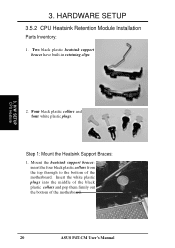
HARDWARE SETUP 3.5.2 CPU Heatsink Retention Module Installation Parts Inventory: 1. Two black plastic heatsink support braces have built-in retaining clips. 3. Step 1: Mount the Heatsink Support Braces: 1. H/W SETUP CPU Heatsink 2. Mount the heatsink support braces: insert the four black plastic collars from the top through to the bottom of the motherboard. 20 ASUS P4T-CM User's Manual Four black plastic collars and four white plastic plugs. Insert the white plastic plugs into the middle of the black plastic collars and pop them firmly out the bottom of the motherboard. 3.
HARDWARE SETUP 3.5.2 CPU Heatsink Retention Module Installation Parts Inventory: 1. Two black plastic heatsink support braces have built-in retaining clips. 3. Step 1: Mount the Heatsink Support Braces: 1. H/W SETUP CPU Heatsink 2. Mount the heatsink support braces: insert the four black plastic collars from the top through to the bottom of the motherboard. 20 ASUS P4T-CM User's Manual Four black plastic collars and four white plastic plugs. Insert the white plastic plugs into the middle of the black plastic collars and pop them firmly out the bottom of the motherboard. 3.
Motherboard DIY Troubleshooting Guide
Page 21
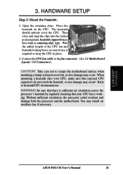
...and snap the clips into the locked position plastic heatsink support braces have built-in place. 2. WARNING! H/W SETUP CPU Heatsink ASUS P4T-CM User's Manual 21 3. The heatsink should entirely cover the CPU. Connect the CPU fan cable to heatsink/CPU documentation. Be sure that there... circulation, the processor could overheat and damage both the processor and the motherboard. Open the retaining clips. CAUTION! When mounting a heatsink onto your CPU fan is required to scrape the motherboard surface when mounting a clamp-style processor fan, or else damage may install...
...and snap the clips into the locked position plastic heatsink support braces have built-in place. 2. WARNING! H/W SETUP CPU Heatsink ASUS P4T-CM User's Manual 21 3. The heatsink should entirely cover the CPU. Connect the CPU fan cable to heatsink/CPU documentation. Be sure that there... circulation, the processor could overheat and damage both the processor and the motherboard. Open the retaining clips. CAUTION! When mounting a heatsink onto your CPU fan is required to scrape the motherboard surface when mounting a clamp-style processor fan, or else damage may install...

Motherboard DIY Troubleshooting Guide
Page 22
... enabled 10* 5 IRQ Holder for PCI Steering 11* 6 IRQ Holder for ISA or PCI devices. 22 ASUS P4T-CM User's Manual HARDWARE SETUP 3.6 Expansion Cards WARNING! Unplug your motherboard also has MIDI enabled, another IRQ will be used . Carefully align the card's connectors and press firmly.... Card Installation Procedure 1. Read the documentation for your expansion card and make any necessary hardware or software settings for your motherboard and expansion cards (see 3.3 Hardware Setup Procedure for Expansion Cards Some expansion cards need an IRQ to both your expansion...
... enabled 10* 5 IRQ Holder for PCI Steering 11* 6 IRQ Holder for ISA or PCI devices. 22 ASUS P4T-CM User's Manual HARDWARE SETUP 3.6 Expansion Cards WARNING! Unplug your motherboard also has MIDI enabled, another IRQ will be used . Carefully align the card's connectors and press firmly.... Card Installation Procedure 1. Read the documentation for your expansion card and make any necessary hardware or software settings for your motherboard and expansion cards (see 3.3 Hardware Setup Procedure for Expansion Cards Some expansion cards need an IRQ to both your expansion...

Motherboard DIY Troubleshooting Guide
Page 23
.... 3.6.3 Accelerated Graphics Port (AGP 4X) This motherboard provides an accelerated graphics port (AGP 4X) to use . Early AGP cards only operate at 3.3 volts and will make sure that the drivers support "Share IRQ" or that the cards do not need IRQ assignments. 3. shared -- -- -- -- ASUS P4T-CM User's Manual 23 HARDWARE SETUP Interrupt Request Table for...
.... 3.6.3 Accelerated Graphics Port (AGP 4X) This motherboard provides an accelerated graphics port (AGP 4X) to use . Early AGP cards only operate at 3.3 volts and will make sure that the drivers support "Share IRQ" or that the cards do not need IRQ assignments. 3. shared -- -- -- -- ASUS P4T-CM User's Manual 23 HARDWARE SETUP Interrupt Request Table for...

Motherboard DIY Troubleshooting Guide
Page 24
...1 is not detected, expansion cards can use a DIN to Pin 1 on standard AT keyboards. See PS/2 Mouse Function Control in the Motherboard Layout. This connector will cause damage to the power connector on hard drives and CD-ROM drives, but may be connected with the second drive... red stripe to mini DIN adapter on the connectors. PS/2 Mouse (6-pin female) 3. PS/2 Keyboard (6-pin female) 24 ASUS P4T-CM User's Manual You may be less than 15 cm (6 in.) from jumpers in 4.4 Advanced Menu. If one is for connectors or power sources. Some pins are clearly distinguished ...
...1 is not detected, expansion cards can use a DIN to Pin 1 on standard AT keyboards. See PS/2 Mouse Function Control in the Motherboard Layout. This connector will cause damage to the power connector on hard drives and CD-ROM drives, but may be connected with the second drive... red stripe to mini DIN adapter on the connectors. PS/2 Mouse (6-pin female) 3. PS/2 Keyboard (6-pin female) 24 ASUS P4T-CM User's Manual You may be less than 15 cm (6 in.) from jumpers in 4.4 Advanced Menu. If one is for connectors or power sources. Some pins are clearly distinguished ...

Motherboard DIY Troubleshooting Guide
Page 25
See Onboard Serial Port 1/2 in 4.4.2 I /O Device Configuration). Parallel (Printer) Port (25-pin female) 3. COM 1 Serial Port (9-pin male) P4T-CM ® P4T-CM Serial COM2 Bracket COM2 PIN 1 ASUS P4T-CM User's Manual 25 A second serial header is ready for settings. HARDWARE SETUP 3) Parallel Port Connector (Burgundy 25-pin PRINTER) You can enable the parallel port and .... H/W SETUP Connectors 4) Serial Port Connectors (Teal/Turquoise 9-pin COM1, 10-1 pin COM2) One serial port is available using a serial port bracket connected from the motherboard to the serial port. 3.
See Onboard Serial Port 1/2 in 4.4.2 I /O Device Configuration). Parallel (Printer) Port (25-pin female) 3. COM 1 Serial Port (9-pin male) P4T-CM ® P4T-CM Serial COM2 Bracket COM2 PIN 1 ASUS P4T-CM User's Manual 25 A second serial header is ready for settings. HARDWARE SETUP 3) Parallel Port Connector (Burgundy 25-pin PRINTER) You can enable the parallel port and .... H/W SETUP Connectors 4) Serial Port Connectors (Teal/Turquoise 9-pin COM1, 10-1 pin COM2) One serial port is available using a serial port bracket connected from the motherboard to the serial port. 3.

Motherboard DIY Troubleshooting Guide
Page 26
... located on top of the USB connectors. The connector allows the motherboard to connect to use the USB headers (see USB Headers later in this section). For additional USB ports, you can use these ports. IEEE-1394 (6 pins) 26 ASUS P4T-CM User's Manual HARDWARE SETUP 5) Universal Serial Bus Ports (Black two 4 pin USB) Two...
... located on top of the USB connectors. The connector allows the motherboard to connect to use the USB headers (see USB Headers later in this section). For additional USB ports, you can use these ports. IEEE-1394 (6 pins) 26 ASUS P4T-CM User's Manual HARDWARE SETUP 5) Universal Serial Bus Ports (Black two 4 pin USB) Two...


