
Motherboard DIY Troubleshooting Guide
Page 1
Motherboard P4SGX-MX User Guide
Motherboard P4SGX-MX User Guide
Motherboard DIY Troubleshooting Guide
Page 3
Features Contents Notices v Safety information vi About this guide vii ASUS contact information viii P4SGX-MX specifications summary ix Chapter 1: Product introduction 1.1 Welcome 1-2 1.2 Package contents 1-2 1.3 Motherboard components 1-3 1.4 Special Features 1-6 1.5 Motherboard layout 1-7 1.6 Before you proceed 1-8 1.7 Motherboard installation 1-9 1.7.1 Placement direction 1-9 1.7.2 Screw holes 1-9 1.8 Central Processing Unit (CPU 1-10 1.8.1 Overview 1-11 1.8.2 Installing the CPU 1-11 1.9 System memory 1-12 1.10 Expansion slots...
Features Contents Notices v Safety information vi About this guide vii ASUS contact information viii P4SGX-MX specifications summary ix Chapter 1: Product introduction 1.1 Welcome 1-2 1.2 Package contents 1-2 1.3 Motherboard components 1-3 1.4 Special Features 1-6 1.5 Motherboard layout 1-7 1.6 Before you proceed 1-8 1.7 Motherboard installation 1-9 1.7.1 Placement direction 1-9 1.7.2 Screw holes 1-9 1.8 Central Processing Unit (CPU 1-10 1.8.1 Overview 1-11 1.8.2 Installing the CPU 1-11 1.9 System memory 1-12 1.10 Expansion slots...

Motherboard DIY Troubleshooting Guide
Page 6
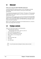
...any damage, contact your dealer immediately. • To avoid short circuits, keep paper clips, screws, and staples away from the motherboard, ensure that all cables are correctly connected and the power cables are unplugged. • Seek professional assistance before the signal cables ... cables from connectors, slots, sockets and circuitry. • Avoid dust, humidity, and temperature extremes. Operation safety • Before installing the motherboard and adding devices on a stable surface. • If you are connected. Do not place the product in your power supply is broken...
...any damage, contact your dealer immediately. • To avoid short circuits, keep paper clips, screws, and staples away from the motherboard, ensure that all cables are correctly connected and the power cables are unplugged. • Seek professional assistance before the signal cables ... cables from connectors, slots, sockets and circuitry. • Avoid dust, humidity, and temperature extremes. Operation safety • Before installing the motherboard and adding devices on a stable surface. • If you are connected. Do not place the product in your power supply is broken...

Motherboard DIY Troubleshooting Guide
Page 11
It includes brief descriptions of the motherboard components, and illustrations of the P4SGX-MX motherboard. Product introduction Chapter 1 This chapter describes the features of the layout, jumper settings, and connectors.
It includes brief descriptions of the motherboard components, and illustrations of the P4SGX-MX motherboard. Product introduction Chapter 1 This chapter describes the features of the layout, jumper settings, and connectors.
Motherboard DIY Troubleshooting Guide
Page 12
...Chapter 1: Product introduction Supporting up to 2GB of system memory with the list below. 1.2 Package contents Check your P4SGX-MX package for the following items. ASUS P4SGX-MX motherboard ATX form factor: 9.6 in x 9.6 in 478-pin package coupled with the SiS® 650GX chipset to ...enter the world of ASUS quality motherboards! 1.1 Welcome! Before you for a cost-effective desktop platform solution. The ASUS P4SGX-MX motherboard delivers a host of new features and latest technologies making it , check the items in ...
...Chapter 1: Product introduction Supporting up to 2GB of system memory with the list below. 1.2 Package contents Check your P4SGX-MX package for the following items. ASUS P4SGX-MX motherboard ATX form factor: 9.6 in x 9.6 in 478-pin package coupled with the SiS® 650GX chipset to ...enter the world of ASUS quality motherboards! 1.1 Welcome! Before you for a cost-effective desktop platform solution. The ASUS P4SGX-MX motherboard delivers a host of new features and latest technologies making it , check the items in ...

Motherboard DIY Troubleshooting Guide
Page 13
Refer to facilitate the installation and future upgrades. 1.3 Motherboard components Before you install the motherboard, learn about its major components and available features to the succeeding pages for the component descriptions. 1 2 34 56 16 15 14 13 12 11 17 18 19 27 26 25 24 23 ASUS P4SGX-MX motherboard user guide 7 8 9 10 20 21 22 1-3
Refer to facilitate the installation and future upgrades. 1.3 Motherboard components Before you install the motherboard, learn about its major components and available features to the succeeding pages for the component descriptions. 1 2 34 56 16 15 14 13 12 11 17 18 19 27 26 25 24 23 ASUS P4SGX-MX motherboard user guide 7 8 9 10 20 21 22 1-3
Motherboard DIY Troubleshooting Guide
Page 14
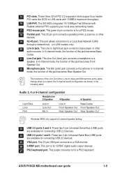
... controllers, IDE Master/Slave controllers, and the MuTIOL Connect to PCI Bridge. 10 Flash ROM. The power supply must have at least 1A on the motherboard. The ADI AD1980 is slotted to prevent incorrect insertion of the floppy disk cable. 13 Standby power LED. Referred to as a reminder to 2GB system...
... controllers, IDE Master/Slave controllers, and the MuTIOL Connect to PCI Bridge. 10 Flash ROM. The power supply must have at least 1A on the motherboard. The ADI AD1980 is slotted to prevent incorrect insertion of the floppy disk cable. 13 Standby power LED. Referred to as a reminder to 2GB system...
Motherboard DIY Troubleshooting Guide
Page 15
... function of this jack becomes Rear Speaker Out. These two 4-pin Universal Serial Bus (USB) ports are available for connecting USB 2.0 devices. 25 VGA port. ASUS P4SGX-MX motherboard user guide 1-5 These two 4-pin Universal Serial Bus (USB) ports are available for a PS/2 mouse. 18 Parallel port. This Line In (light blue) jack connects...
... function of this jack becomes Rear Speaker Out. These two 4-pin Universal Serial Bus (USB) ports are available for connecting USB 2.0 devices. 25 VGA port. ASUS P4SGX-MX motherboard user guide 1-5 These two 4-pin Universal Serial Bus (USB) ports are available for a PS/2 mouse. 18 Parallel port. This Line In (light blue) jack connects...

Motherboard DIY Troubleshooting Guide
Page 16
... Powerful Integrated Graphics The P4SGX-MX delivers powerful integrated SiS Real® 256 2D and 3D graphics performance for each parameter. C.P.R. (CPU Parameter Recall) (page 1-15) When the system hangs due to clear the CMOS data. Unlike other competing vendors' products, ASUS motherboards now enable users to ... Audio System can update BIOS before entering operating system. 1.4 Special Features 1.4.1 Product highlights Latest processor technology The P4SGX-MX motherboard supports the latest Intel® Pentium® 4 Processor via a 478-pin surface mount ZIF socket.
... Powerful Integrated Graphics The P4SGX-MX delivers powerful integrated SiS Real® 256 2D and 3D graphics performance for each parameter. C.P.R. (CPU Parameter Recall) (page 1-15) When the system hangs due to clear the CMOS data. Unlike other competing vendors' products, ASUS motherboards now enable users to ... Audio System can update BIOS before entering operating system. 1.4 Special Features 1.4.1 Product highlights Latest processor technology The P4SGX-MX motherboard supports the latest Intel® Pentium® 4 Processor via a 478-pin surface mount ZIF socket.

Motherboard DIY Troubleshooting Guide
Page 17
...DIMM Socket 1 (64/72-bit, 168-pin module) DIMM Socket 1 (64/72-bit, 168-pin module) SEC_IDE1 PRI_IDE1 24.4cm (9.6in) 1.5 Motherboard layout PS/2KBMS T: Mouse B: Keyboard USBPWR_34 USBPWR_12 SPDIF1 CPU_FAN1 24.4cm (9.6in) ATX Power Connector PARALLEL PORT VGA1 USB20_12 Bottom: USB3 USB4 Top: RJ...23 01 23 CR2032 3V Lithium Cell CMOS Power Audio Codec MDC1 CHA_FAN1 SB_PWR1 FP_AUDIO1 PCI Slot 1 ® PCI Slot 2 P4SGX-MX PCI Slot 3 FLOPPY1 USB_56 SiS962L MuTLOL Media I/0 USBPWR_56 Super I/O CLRTC1 GAME1 2Mbit Flash BIOS COM1 PANEL1 ASUS P4SGX-MX motherboard user guide 1-7
...DIMM Socket 1 (64/72-bit, 168-pin module) DIMM Socket 1 (64/72-bit, 168-pin module) SEC_IDE1 PRI_IDE1 24.4cm (9.6in) 1.5 Motherboard layout PS/2KBMS T: Mouse B: Keyboard USBPWR_34 USBPWR_12 SPDIF1 CPU_FAN1 24.4cm (9.6in) ATX Power Connector PARALLEL PORT VGA1 USB20_12 Bottom: USB3 USB4 Top: RJ...23 01 23 CR2032 3V Lithium Cell CMOS Power Audio Codec MDC1 CHA_FAN1 SB_PWR1 FP_AUDIO1 PCI Slot 1 ® PCI Slot 2 P4SGX-MX PCI Slot 3 FLOPPY1 USB_56 SiS962L MuTLOL Media I/0 USBPWR_56 Super I/O CLRTC1 GAME1 2Mbit Flash BIOS COM1 PANEL1 ASUS P4SGX-MX motherboard user guide 1-7

Motherboard DIY Troubleshooting Guide
Page 18
...5. 1.6 Before you proceed Take note of the following precautions before you install motherboard components or change any component. 2. Hold components by the edges to avoid touching the ICs on this motherboard! 1-8 Chapter 1: Product introduction Whenever you uninstall any component, place it on... handling components to static electricity. 3. When lit, the green LED (SB_PWR1) indicates that you install or remove any motherboard component. ® P4SGX-MX P4SGX-MX Onboard LED SB_PWR1 ON Standby Power OFF Powered Off Install only 1.5V AGP cards on them due to avoid damaging them...
...5. 1.6 Before you proceed Take note of the following precautions before you install motherboard components or change any component. 2. Hold components by the edges to avoid touching the ICs on this motherboard! 1-8 Chapter 1: Product introduction Whenever you uninstall any component, place it on... handling components to static electricity. 3. When lit, the green LED (SB_PWR1) indicates that you install or remove any motherboard component. ® P4SGX-MX P4SGX-MX Onboard LED SB_PWR1 ON Standby Power OFF Powered Off Install only 1.5V AGP cards on them due to avoid damaging them...

Motherboard DIY Troubleshooting Guide
Page 19
... 9.6 inches x 9.6 inches (24.5 cm x 24.5 cm). Make sure to the chassis. The motherboard uses the micro-ATX form factor that you install the motherboard, study the configuration of your chassis to the rear part of the chassis ASUS P4SGX-MX motherboard user guide 1-9 1.7 Motherboard installation Before you place it . Place this side towards the rear of the...
... 9.6 inches x 9.6 inches (24.5 cm x 24.5 cm). Make sure to the chassis. The motherboard uses the micro-ATX form factor that you install the motherboard, study the configuration of your chassis to the rear part of the chassis ASUS P4SGX-MX motherboard user guide 1-9 1.7 Motherboard installation Before you place it . Place this side towards the rear of the...

Motherboard DIY Troubleshooting Guide
Page 20
...® Pentium® 4 Processor in the illustration that should match a specific corner of the CPU socket. The socket is not supported by ASUS. This processor supports *533/400MHz front side bus (FSB), and allows data transfer rates of the CPU into the socket may bend the pins... and severely damage the CPU! *FSB533 support tested by this motherboard. 1-10 Chapter 1: Product introduction This mark indicates the processor Pin 1 that the CPU has a gold triangular mark on 0.13 micron process. 1.8 Central...
...® Pentium® 4 Processor in the illustration that should match a specific corner of the CPU socket. The socket is not supported by ASUS. This processor supports *533/400MHz front side bus (FSB), and allows data transfer rates of the CPU into the socket may bend the pins... and severely damage the CPU! *FSB533 support tested by this motherboard. 1-10 Chapter 1: Product introduction This mark indicates the processor Pin 1 that the CPU has a gold triangular mark on 0.13 micron process. 1.8 Central...

Motherboard DIY Troubleshooting Guide
Page 21
...with the heatsink package. 7. Gold Mark The CPU fits only in place. The lever clicks on the side tab to the CPU_FAN1 connector on the motherboard. 2. ASUS P4SGX-MX motherboard user guide 1-11 Carefully insert the CPU into the socket to install a CPU. 1. Connect the CPU fan cable to indicate that its marked ...lever. 4. Position the CPU above the socket such that it is in completely. 90 - 100 3. Locate the 478-pin ZIF socket on the motherboard. DO NOT force the CPU into the socket until it up to 90°-100° angle, otherwise the CPU does not fit in place...
...with the heatsink package. 7. Gold Mark The CPU fits only in place. The lever clicks on the side tab to the CPU_FAN1 connector on the motherboard. 2. ASUS P4SGX-MX motherboard user guide 1-11 Carefully insert the CPU into the socket to install a CPU. 1. Connect the CPU fan cable to indicate that its marked ...lever. 4. Position the CPU above the socket such that it is in completely. 90 - 100 3. Locate the 478-pin ZIF socket on the motherboard. DO NOT force the CPU into the socket until it up to 90°-100° angle, otherwise the CPU does not fit in place...

Motherboard DIY Troubleshooting Guide
Page 22
... DIMM. DDR DIMM notch 1. Unlock a DIMM socket by ASUS.Visit the ASUS website (www.asus.com) for PC2700 Qualified Vendor List (QVL). ® P4SGX-MX P4SGX-MX 168-Pin DIMM Sockets 88 Pins 60 Pins 20 Pins 104 Pins ® P4SGX-MX 80 Pins P4SGX-MX 184-Pin DDR DIMM Sockets 1. DDR and SDRAM memory slots .../100 SDRAM DIMMs. *PC2700 support tested by pressing the retaining clips outward. 2. Align a DIMM on the socket. 3. 1.9 System memory The motherboard has two Double Data Rate (DDR) DIMM sockets and two Single Data Rate (SDR) DIMM sockets that the notch on the DIMM matches the ...
... DIMM. DDR DIMM notch 1. Unlock a DIMM socket by ASUS.Visit the ASUS website (www.asus.com) for PC2700 Qualified Vendor List (QVL). ® P4SGX-MX P4SGX-MX 168-Pin DIMM Sockets 88 Pins 60 Pins 20 Pins 104 Pins ® P4SGX-MX 80 Pins P4SGX-MX 184-Pin DDR DIMM Sockets 1. DDR and SDRAM memory slots .../100 SDRAM DIMMs. *PC2700 support tested by pressing the retaining clips outward. 2. Align a DIMM on the socket. 3. 1.9 System memory The motherboard has two Double Data Rate (DDR) DIMM sockets and two Single Data Rate (SDR) DIMM sockets that the notch on the DIMM matches the ...
Motherboard DIY Troubleshooting Guide
Page 23
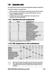
...- - AGP slot shared - - - - Onboard USB controller 1 - - - - shared - - See Chapter 2 for this motherboard A B C D E PCI slot 1 - used -- -- -- F - - - - - used - - - ASUS P4SGX-MX motherboard user guide 1-13 Install an expansion card following the instructions that the cards do not need IRQ assignments. shared - Onboard USB 2.0 controller... an expansion card: 1. Onboard USB controller 3 - - - - - Onboard VGA shared - - - - 1.10 Expansion slots The motherboard has three PCI slots and one Accelerated Graphics Port (AGP) slot.
...- - AGP slot shared - - - - Onboard USB controller 1 - - - - shared - - See Chapter 2 for this motherboard A B C D E PCI slot 1 - used -- -- -- F - - - - - used - - - ASUS P4SGX-MX motherboard user guide 1-13 Install an expansion card following the instructions that the cards do not need IRQ assignments. shared - Onboard USB 2.0 controller... an expansion card: 1. Onboard USB controller 3 - - - - - Onboard VGA shared - - - - 1.10 Expansion slots The motherboard has three PCI slots and one Accelerated Graphics Port (AGP) slot.
Motherboard DIY Troubleshooting Guide
Page 25
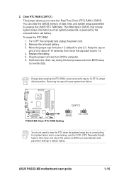
... to default values. Removing the cap will cause system boot failure! ® P4SGX-MX CLRTC1 12 23 Normal (Default) Clear CMOS P4SGX-MX Clear RTC RAM Setting You do not need to clear the RTC when the system hangs due to pins 2-3. ASUS P4SGX-MX motherboard user guide 1-15 To erase the RTC RAM: 1. Move the jumper cap...
... to default values. Removing the cap will cause system boot failure! ® P4SGX-MX CLRTC1 12 23 Normal (Default) Clear CMOS P4SGX-MX Clear RTC RAM Setting You do not need to clear the RTC when the system hangs due to pins 2-3. ASUS P4SGX-MX motherboard user guide 1-15 To erase the RTC RAM: 1. Move the jumper cap...

Motherboard DIY Troubleshooting Guide
Page 26
... to be both master devices with pin 5 plug). Pin 20 on the IDE ribbon cable to PIN 1 SEC_IDE1 PRI_IDE1 1-16 ® P4SGX-MX P4SGX-MX IDE Connectors PIN 1 PIN 1 Chapter 1: Product introduction 1.12 Connectors This section describes and illustrates the internal connectors on the floppy ribbon cable... may configure two hard disks to the hard disk documentation for the secondary IDE connector. FLOPPY1 ® P4SGX-MX PIN 1 NOTE: Orient the red markings on the motherboard. 1. If you connect the cables. NOTE: Orient the red markings on each IDE connector is recommended that...
... to be both master devices with pin 5 plug). Pin 20 on the IDE ribbon cable to PIN 1 SEC_IDE1 PRI_IDE1 1-16 ® P4SGX-MX P4SGX-MX IDE Connectors PIN 1 PIN 1 Chapter 1: Product introduction 1.12 Connectors This section describes and illustrates the internal connectors on the floppy ribbon cable... may configure two hard disks to the hard disk documentation for the secondary IDE connector. FLOPPY1 ® P4SGX-MX PIN 1 NOTE: Orient the red markings on the motherboard. 1. If you connect the cables. NOTE: Orient the red markings on each IDE connector is recommended that...

Motherboard DIY Troubleshooting Guide
Page 27
... -12.0VDC +3.3VDC +12.0VDC +5VSB PWR_OK COM +5.0VDC COM +5.0VDC COM +3.3VDC +3.3VDC ® P4SGX-MX ATX12V1 +12V DC P4SGX-MX ATX Power Connectors COM +12V DC COM ASUS P4SGX-MX motherboard user guide 1-17 Connect the bracket cable to the CPU. The minimum recommended wattage is inadequate. COM1 PIN ...1 ® P4SGX-MX P4SGX-MX COM1 Connector 4. The plugs from the power supply are designed to an ATX 12V power supply....
... -12.0VDC +3.3VDC +12.0VDC +5VSB PWR_OK COM +5.0VDC COM +5.0VDC COM +3.3VDC +3.3VDC ® P4SGX-MX ATX12V1 +12V DC P4SGX-MX ATX Power Connectors COM +12V DC COM ASUS P4SGX-MX motherboard user guide 1-17 Connect the bracket cable to the CPU. The minimum recommended wattage is inadequate. COM1 PIN ...1 ® P4SGX-MX P4SGX-MX COM1 Connector 4. The plugs from the power supply are designed to an ATX 12V power supply....

Motherboard DIY Troubleshooting Guide
Page 28
...to the fan connectors. The GAME/MIDI port on the fan connectors! These are not jumpers! CPU_FAN1 GND +12V Rotation ® P4SGX-MX GND +12V Rotation CHA_FAN1 P4SGX-MX 12-Volt Cooling Fan Power 6. The USB/GAME module is purchased separately. +5V J1B2 J1CY GND GND J1CX J1B1 +5V ®...; P4SGX-MX P4SGX-MX Game Connector GAME1 MIDI_IN J2B2 J2CY MIDI_OUT J2CX J2B1 +5V 1-18 Chapter 1: Product introduction Do not forget to connect the fan cables to the fan connectors on the motherboard, making sure that the black wire of each cable ...
...to the fan connectors. The GAME/MIDI port on the fan connectors! These are not jumpers! CPU_FAN1 GND +12V Rotation ® P4SGX-MX GND +12V Rotation CHA_FAN1 P4SGX-MX 12-Volt Cooling Fan Power 6. The USB/GAME module is purchased separately. +5V J1B2 J1CY GND GND J1CX J1B1 +5V ®...; P4SGX-MX P4SGX-MX Game Connector GAME1 MIDI_IN J2B2 J2CY MIDI_OUT J2CX J2B1 +5V 1-18 Chapter 1: Product introduction Do not forget to connect the fan cables to the fan connectors on the motherboard, making sure that the black wire of each cable ...


