User Guide
Page 1
Motherboard P4SD-LA ( Oxford ) User Guide
Motherboard P4SD-LA ( Oxford ) User Guide
User Guide
Page 2
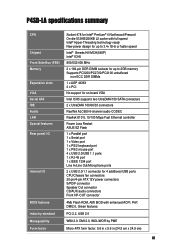
Jumper 7 6. Expansion slots 5 Standard interrupt assignments 5 IRQ assignments for this motherboard 5 PCI slots 6 AGP slot 6 5. Motherboard layout 1 2. Connectors 8 ii Central Processing Unit (CPU 2 3. System memory 3 Memory configurations 3 Installing a DIMM 4 4. Checklist Contents P4SD-LA specifications summary iii 1.
Jumper 7 6. Expansion slots 5 Standard interrupt assignments 5 IRQ assignments for this motherboard 5 PCI slots 6 AGP slot 6 5. Motherboard layout 1 2. Connectors 8 ii Central Processing Unit (CPU 2 3. System memory 3 Memory configurations 3 Installing a DIMM 4 4. Checklist Contents P4SD-LA specifications summary iii 1.
User Guide
Page 3
P4SD-LA specifications summary CPU Chipset Front Side Bus (FSB) Memory Expansion slots VGA Serial ATA IDE Audio LAN Special features Rear panel I/O Internal I/O BIOS features Industry standard Manageability Form factor Socket 478 for Intel® Pentium® 4 Northwood/Prescott On-die 512KB/... UltraDMA/150 SATA connectors 2 x UltraDMA 100/66/33 connectors RealTek ALC650 6-channel audio CODEC Realtek 8101L 10/100 Mbps Fast Ethernet controller Power Loss Restart ASUS EZ Flash 1 x Parallel port 1 x Serial port 1 x Video port 1 x PS/2 keyboard port 1 x PS/2 mouse port 4 x USB 2.0/USB 1.1 ports...
P4SD-LA specifications summary CPU Chipset Front Side Bus (FSB) Memory Expansion slots VGA Serial ATA IDE Audio LAN Special features Rear panel I/O Internal I/O BIOS features Industry standard Manageability Form factor Socket 478 for Intel® Pentium® 4 Northwood/Prescott On-die 512KB/... UltraDMA/150 SATA connectors 2 x UltraDMA 100/66/33 connectors RealTek ALC650 6-channel audio CODEC Realtek 8101L 10/100 Mbps Fast Ethernet controller Power Loss Restart ASUS EZ Flash 1 x Parallel port 1 x Serial port 1 x Video port 1 x PS/2 keyboard port 1 x PS/2 mouse port 4 x USB 2.0/USB 1.1 ports...
User Guide
Page 5
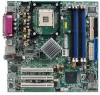
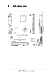
1. Motherboard layout PS/2 T: Mouse B: Keyboard COM1 24.5cm (9.64in) Socket 478 CPU_FAN1 Super I/O FLOPPY1 BUZZER P4SD-LA DDR DIMM1 (64/72 bit, 184-pin module) DDR DIMM2 (64/72 bit, 184-pin module) PARALLEL PORT VGA Bottom: USB1 USB2 Top: 1394 Bottom: ... PHY 01 23 BATTERY1 Intel ICH5 Chipset P31 P30 J19 4Mb BIOS USB2 USB1 HPANEL ATX Power Connector 24.5cm (9.64in) SECONDARY IDE PRIMARY IDE ASUS P4SD-LA motherboard 1
1. Motherboard layout PS/2 T: Mouse B: Keyboard COM1 24.5cm (9.64in) Socket 478 CPU_FAN1 Super I/O FLOPPY1 BUZZER P4SD-LA DDR DIMM1 (64/72 bit, 184-pin module) DDR DIMM2 (64/72 bit, 184-pin module) PARALLEL PORT VGA Bottom: USB1 USB2 Top: 1394 Bottom: ... PHY 01 23 BATTERY1 Intel ICH5 Chipset P31 P30 J19 4Mb BIOS USB2 USB1 HPANEL ATX Power Connector 24.5cm (9.64in) SECONDARY IDE PRIMARY IDE ASUS P4SD-LA motherboard 1
User Guide
Page 6
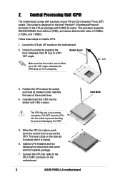
... motherboard. 2 ASUS P4SD-LA motherboard Gold Mark DO NOT force the CPU into the socket until it is lifted up to secure the CPU. Follow these steps to prevent bending the pins and damaging the CPU! 5. Central Processing Unit (CPU) The motherboard comes with a surface mount 478-pin Zero Insertion Force (ZIF) socket. Locate the 478-pin ZIF socket on the motherboard...
... motherboard. 2 ASUS P4SD-LA motherboard Gold Mark DO NOT force the CPU into the socket until it is lifted up to secure the CPU. Follow these steps to prevent bending the pins and damaging the CPU! 5. Central Processing Unit (CPU) The motherboard comes with a surface mount 478-pin Zero Insertion Force (ZIF) socket. Locate the 478-pin ZIF socket on the motherboard...
User Guide
Page 7
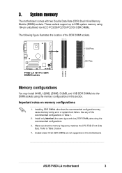
...pin unbuffered non-ECC PC3200/PC2700/PC2100 DDR DIMMs. The following figure illustrates the location of the recommended configurations in this motherboard. ASUS P4SD-LA motherboard 3 Refer to 2GB system memory using the recommended configurations. 3. Installing DDR DIMMs other than the recommended configurations may ...Side Bus). 3. Use any of the DDR DIMM sockets. 104 Pins P4SD-LA DIMM1 DIMM2 P4SD-LA 184-Pin DDR DIMM Sockets 80 Pins Memory configurations You may cause memory sizing error or system boot failure. These sockets support up to Table 2 below. 4. Double-sided...
...pin unbuffered non-ECC PC3200/PC2700/PC2100 DDR DIMMs. The following figure illustrates the location of the recommended configurations in this motherboard. ASUS P4SD-LA motherboard 3 Refer to 2GB system memory using the recommended configurations. 3. Installing DDR DIMMs other than the recommended configurations may ...Side Bus). 3. Use any of the DDR DIMM sockets. 104 Pins P4SD-LA DIMM1 DIMM2 P4SD-LA 184-Pin DDR DIMM Sockets 80 Pins Memory configurations You may cause memory sizing error or system boot failure. These sockets support up to Table 2 below. 4. Double-sided...
User Guide
Page 8
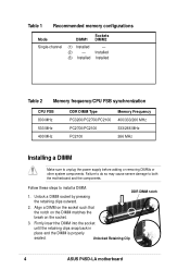
... may cause severe damage to unplug the power supply before adding or removing DIMMs or other system components. Unlocked Retaining Clip 4 ASUS P4SD-LA motherboard Installed (3) Installed Installed Table 2 Memory frequency/CPU FSB synchronization CPU FSB 800 MHz 533 MHz 400 MHz DDR DIMM Type PC3200... Memory Frequency 400/333/266 MHz 333/266 MHz 266 MHz Installing a DIMM Make sure to both the motherboard and the components. DDR DIMM notch 2. Unlock a DIMM socket by pressing the retaining clips outward. Follow these steps to install a DIMM. 1. Table 1 Recommended memory ...
... may cause severe damage to unplug the power supply before adding or removing DIMMs or other system components. Unlocked Retaining Clip 4 ASUS P4SD-LA motherboard Installed (3) Installed Installed Table 2 Memory frequency/CPU FSB synchronization CPU FSB 800 MHz 533 MHz 400 MHz DDR DIMM Type PC3200... Memory Frequency 400/333/266 MHz 333/266 MHz 266 MHz Installing a DIMM Make sure to both the motherboard and the components. DDR DIMM notch 2. Unlock a DIMM socket by pressing the retaining clips outward. Follow these steps to install a DIMM. 1. Table 1 Recommended memory ...
User Guide
Page 9
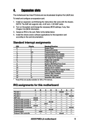
... 2 - - - - - - Onboard USB controller 3 - - Onboard audio - To install and configure an expansion card: 1. Install the drivers and/or software applications for this motherboard A B C D E F GH PCI slot 1 - - - - - shared - - - - used - - - - - - shared - - - - Install an... BIOS information. 3. shared - - PCI slot 3 shared AGP slot shared Onboard USB controller 1 shared Onboard USB controller 2 - - - ASUS P4SD-LA motherboard 5 used - - - - - See Chapter 2 for ISA or PCI devices. shared - - Assign an IRQ to the tables below....
... 2 - - - - - - Onboard USB controller 3 - - Onboard audio - To install and configure an expansion card: 1. Install the drivers and/or software applications for this motherboard A B C D E F GH PCI slot 1 - - - - - shared - - - - used - - - - - - shared - - - - Install an... BIOS information. 3. shared - - PCI slot 3 shared AGP slot shared Onboard USB controller 1 shared Onboard USB controller 2 - - - ASUS P4SD-LA motherboard 5 used - - - - - See Chapter 2 for ISA or PCI devices. shared - - Assign an IRQ to the tables below....

User Guide
Page 10
... slots There are three 32-bit PCI slots on this motherboard! The slots support PCI cards such as a LAN card, SCSI card, USB card, and other cards that you ask for one with PCI specifications. Note ... that supports +0.8V AGP 8X and +1.5V AGP 4X cards. AGP slot This motherboard has an Accelerated Graphics Port (AGP) slot that they fit the AGP slot on your motherboard. AGP Card without Retention Notch P4SD-LA Accelerated Graphics Port (AGP8X) P4SD-LA 6 ASUS P4SD-LA motherboard When you buy an AGP card, make sure that comply with +0.8V+1.5V...
... slots There are three 32-bit PCI slots on this motherboard! The slots support PCI cards such as a LAN card, SCSI card, USB card, and other cards that you ask for one with PCI specifications. Note ... that supports +0.8V AGP 8X and +1.5V AGP 4X cards. AGP slot This motherboard has an Accelerated Graphics Port (AGP) slot that they fit the AGP slot on your motherboard. AGP Card without Retention Notch P4SD-LA Accelerated Graphics Port (AGP8X) P4SD-LA 6 ASUS P4SD-LA motherboard When you buy an AGP card, make sure that comply with +0.8V+1.5V...
User Guide
Page 11
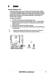
... move the cap back to pins 1-2 (Clear CMOS). 5. The RAM data in CMOS. Removing the cap will cause system boot failure! P4SD-LA P4SD-LA Clear RTC RAM J19 3 2 1 Clear CMOS 3 2 1 Normal (Default) ASUS P4SD-LA motherboard 7 Jumper Clear RTC RAM (3-pin J19) This jumper allows you to re-enter data. Turn OFF the computer and unplug the...
... move the cap back to pins 1-2 (Clear CMOS). 5. The RAM data in CMOS. Removing the cap will cause system boot failure! P4SD-LA P4SD-LA Clear RTC RAM J19 3 2 1 Clear CMOS 3 2 1 Normal (Default) ASUS P4SD-LA motherboard 7 Jumper Clear RTC RAM (3-pin J19) This jumper allows you to re-enter data. Turn OFF the computer and unplug the...
User Guide
Page 12
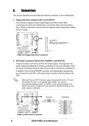
...+5VSB PWR_OK COM +5.0VDC COM +5.0VDC COM +3.3VDC +3.3VDC +5.0VDC +5.0VDC -5.0VDC COM COM COM PS_ON# COM -12.0VDC +3.3VDC 8 ASUS P4SD-LA motherboard The minimum recommended wattage is inadequate. The system may become unstable and may experience difficulty powering up if the power supply is 230W, or 300W... for a fully configured system. 6. P4SD-LA FLOPPY1 NOTE: Orient the red markings on the floppy ribbon cable to fit these connectors in only one end to the motherboard, connect the other end to the floppy drive. (Pin 5 is removed to...
...+5VSB PWR_OK COM +5.0VDC COM +5.0VDC COM +3.3VDC +3.3VDC +5.0VDC +5.0VDC -5.0VDC COM COM COM PS_ON# COM -12.0VDC +3.3VDC 8 ASUS P4SD-LA motherboard The minimum recommended wattage is inadequate. The system may become unstable and may experience difficulty powering up if the power supply is 230W, or 300W... for a fully configured system. 6. P4SD-LA FLOPPY1 NOTE: Orient the red markings on the floppy ribbon cable to fit these connectors in only one end to the motherboard, connect the other end to the floppy drive. (Pin 5 is removed to...
User Guide
Page 13
... the blue connector on each IDE connector is intentional. NOTE: Orient the red markings (usually zigzag) on the UltraDMA cable connector. P4SD-LA SECONDARY IDE PRIMARY IDE P4SD-LA IDE Connectors PIN 1 PIN 1 ASUS P4SD-LA motherboard 9 If you connect nonUltraDMA/100/66 devices to PIN 1. Refer to match the covered hole on the IDE ribbon cable to...
... the blue connector on each IDE connector is intentional. NOTE: Orient the red markings (usually zigzag) on the UltraDMA cable connector. P4SD-LA SECONDARY IDE PRIMARY IDE P4SD-LA IDE Connectors PIN 1 PIN 1 ASUS P4SD-LA motherboard 9 If you connect nonUltraDMA/100/66 devices to PIN 1. Refer to match the covered hole on the IDE ribbon cable to...
User Guide
Page 14
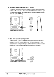
SATA2 GND RSATA_RXP2 RSATA_RXN2 GND RSATA_TXN2 RSATA_TXP2 GND P4SD-LA P4SD-LA SATA Connectors SATA1 GND RSATA_TXP2 RSATA_TXN2 GND RSATA_RXP2 RSATA_RXN2 GND 5. Serial ATA connectors (7-pin SATA1, SATA2) These next generation connectors support the thin Serial ATA ... also connect a 1394-compliant internal hard disk to 150 MB/s data transfer rate, faster than the standard parallel ATA with 133 MB/s (Ultra ATA/133). P4SD-LA TPAGND TPB+12V GND 1394 1 P4SD-LA IEEE-1394 Connectors TPA+ GND TPB+ +12V 10 ASUS P4SD-LA motherboard
SATA2 GND RSATA_RXP2 RSATA_RXN2 GND RSATA_TXN2 RSATA_TXP2 GND P4SD-LA P4SD-LA SATA Connectors SATA1 GND RSATA_TXP2 RSATA_TXN2 GND RSATA_RXP2 RSATA_RXN2 GND 5. Serial ATA connectors (7-pin SATA1, SATA2) These next generation connectors support the thin Serial ATA ... also connect a 1394-compliant internal hard disk to 150 MB/s data transfer rate, faster than the standard parallel ATA with 133 MB/s (Ultra ATA/133). P4SD-LA TPAGND TPB+12V GND 1394 1 P4SD-LA IEEE-1394 Connectors TPA+ GND TPB+ +12V 10 ASUS P4SD-LA motherboard
User Guide
Page 15
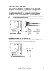
... 2.0 Header 1 5 1 5 USB2 USB1 6 10 6 10 USB+5V LDM2 LDP2 GND USB+5V LDM4 LDP4 GND 7. 6. SPEAKER OUT 1 P4SD-LA Speaker Out Connector P4SD-LA +12V Speak Out-R signal Ground Speak Out-L signal ASUS P4SD-LA motherboard 11 USB headers (10-1 pin USB1, USB2) If the USB ports on USB 1.1 allows faster Internet connection, interactive gaming, and simultaneous running...
... 2.0 Header 1 5 1 5 USB2 USB1 6 10 6 10 USB+5V LDM2 LDP2 GND USB+5V LDM4 LDP4 GND 7. 6. SPEAKER OUT 1 P4SD-LA Speaker Out Connector P4SD-LA +12V Speak Out-R signal Ground Speak Out-L signal ASUS P4SD-LA motherboard 11 USB headers (10-1 pin USB1, USB2) If the USB ports on USB 1.1 allows faster Internet connection, interactive gaming, and simultaneous running...
User Guide
Page 16
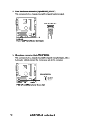
FRONT HP-OUT 1 P4SD-LA Front HeadPhone Header Connector 9. Use a 3-pin audio cable to connect the microphone jack to this connector. Front headphone connector (5-pin FRONT_HP-OUT) This connector is for a chassis-mounted front panel headphone jack. P4SD-LA FRONT OUT-L Signal HP-L Signal Analog Ground FRONT OUT-R Signal HP-R Signal 8. Microphone connector (3-pin FRONT MICIN) This connector is for a chassis-mounted front panel microphone jack. FRONT MICIN MIC Power MIC Input Ground P4SD-LA ront Microphone Connector P4SD-LA 12 ASUS P4SD-LA motherboard
FRONT HP-OUT 1 P4SD-LA Front HeadPhone Header Connector 9. Use a 3-pin audio cable to connect the microphone jack to this connector. Front headphone connector (5-pin FRONT_HP-OUT) This connector is for a chassis-mounted front panel headphone jack. P4SD-LA FRONT OUT-L Signal HP-L Signal Analog Ground FRONT OUT-R Signal HP-R Signal 8. Microphone connector (3-pin FRONT MICIN) This connector is for a chassis-mounted front panel microphone jack. FRONT MICIN MIC Power MIC Input Ground P4SD-LA ront Microphone Connector P4SD-LA 12 ASUS P4SD-LA motherboard
User Guide
Page 17
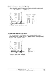
Connect one end of analog sound output. P4SD-LA P4SD-LA Digital Audio Interface SPDI/F +5V SPDIFOUT Ground ASUS P4SD-LA motherboard 13 Internal audio connectors (4-pin CD, AUX) These connectors allow you to the S/PDIF module. Digital audio connector (3-pin SPDI/F) This connector is for an S/... cable to this connector and the other end to receive stereo audio input from sound sources such as a CD-ROM, TV tuner, or MPEG card. P4SD-LA Right Audio Channel Ground Left Audio Channel Right Audio Channel Ground Left Audio Channel 10. CD-IN (Black) AUX(White...
Connect one end of analog sound output. P4SD-LA P4SD-LA Digital Audio Interface SPDI/F +5V SPDIFOUT Ground ASUS P4SD-LA motherboard 13 Internal audio connectors (4-pin CD, AUX) These connectors allow you to the S/PDIF module. Digital audio connector (3-pin SPDI/F) This connector is for an S/... cable to this connector and the other end to receive stereo audio input from sound sources such as a CD-ROM, TV tuner, or MPEG card. P4SD-LA Right Audio Channel Ground Left Audio Channel Right Audio Channel Ground Left Audio Channel 10. CD-IN (Black) AUX(White...
User Guide
Page 18
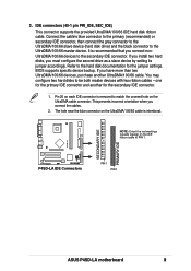
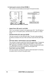
...depending on the system power, and blinks when the system is for rebooting the system without turning off the system power. 14 ASUS P4SD-LA motherboard 12. System panel connector (20-pin HPANEL1) This connector accommodates several system front panel functions. Pressing the power switch while ...PWRBTN) This connector connects a switch that controls the system power. ATX Power Power LED Switch* HPANEL PLED+ PLEDPWR GND P4SD-LA HDLED+ HDLEDGround Reset P4SD-LA Front Panel Audio Connector HDLED Reset SW • System Power LED Lead (3-1 pin PLED) This 3-1 pin connector connects to...
...depending on the system power, and blinks when the system is for rebooting the system without turning off the system power. 14 ASUS P4SD-LA motherboard 12. System panel connector (20-pin HPANEL1) This connector accommodates several system front panel functions. Pressing the power switch while ...PWRBTN) This connector connects a switch that controls the system power. ATX Power Power LED Switch* HPANEL PLED+ PLEDPWR GND P4SD-LA HDLED+ HDLEDGround Reset P4SD-LA Front Panel Audio Connector HDLED Reset SW • System Power LED Lead (3-1 pin PLED) This 3-1 pin connector connects to...


