
P4S8X-MX English User Manaul E1997
Page 1
P4S8X-MX Motherboard
P4S8X-MX Motherboard

P4S8X-MX English User Manaul E1997
Page 3
Contents Notices vi Safety information vii P4S8X-MX specifications summary viii Chapter 1: Product introduction 1.1 Welcome 1-2 1.2 Package contents 1-2 1.3 Special features 1-2 1.4 Before you proceed 1-5 1.5 Motherboard overview 1-6 1.5.1 Motherboard layout 1-6 1.5.2 Placement direction 1-7 1.5.3 Screw holes 1-7 1.6 Central Processing Unit (CPU 1-8 1.6.1 Overview 1-8 1.6.2 Installing the CPU 1-8 1.6.3 Installing the heatsink and fan 1-11 1.7 System memory 1-14 1.7.1 Overview 1-14 1.7.2 Memory ...
Contents Notices vi Safety information vii P4S8X-MX specifications summary viii Chapter 1: Product introduction 1.1 Welcome 1-2 1.2 Package contents 1-2 1.3 Special features 1-2 1.4 Before you proceed 1-5 1.5 Motherboard overview 1-6 1.5.1 Motherboard layout 1-6 1.5.2 Placement direction 1-7 1.5.3 Screw holes 1-7 1.6 Central Processing Unit (CPU 1-8 1.6.1 Overview 1-8 1.6.2 Installing the CPU 1-8 1.6.3 Installing the heatsink and fan 1-11 1.7 System memory 1-14 1.7.1 Overview 1-14 1.7.2 Memory ...

P4S8X-MX English User Manaul E1997
Page 7
...and circuitry. • Avoid dust, humidity, and temperature extremes. Contact a qualified service technician or your area. Operation safety • Before installing the motherboard and adding devices on a stable surface. • If you encounter technical problems with the package. • Before using the product, make sure ...cable from the electrical outlet before relocating the system. • When adding or removing devices to or from the motherboard, ensure that all power cables are unplugged. • Seek professional assistance before using an adapter or extension cord.
...and circuitry. • Avoid dust, humidity, and temperature extremes. Contact a qualified service technician or your area. Operation safety • Before installing the motherboard and adding devices on a stable surface. • If you encounter technical problems with the package. • Before using the product, make sure ...cable from the electrical outlet before relocating the system. • When adding or removing devices to or from the motherboard, ensure that all power cables are unplugged. • Seek professional assistance before using an adapter or extension cord.

P4S8X-MX English User Manaul E1997
Page 8
... Recall) Supports up to 8 USB 2.0 ports ASUS CrashFree BIOS 2 ASUS EZ Flash ASUS MyLogo2™ (continued on the next page) * The motherboard runs at FSB800 when in overclock mode. ** 1. viii When using an FSB533 CPU with 400 MHz DDR memory, the motherboard runs at 333 MHz by default. 2. P4S8X-MX specifications summary CPU Chipset Front Side Bus... PHY Stepless Frequency Selection (SFS) from 100 MHz up to 200 MHz at 1 MHz increment AGP/PCI Asynchronous Mode with 400 MHz DDR memory, the motherboard runs at 400 MHz.
... Recall) Supports up to 8 USB 2.0 ports ASUS CrashFree BIOS 2 ASUS EZ Flash ASUS MyLogo2™ (continued on the next page) * The motherboard runs at FSB800 when in overclock mode. ** 1. viii When using an FSB533 CPU with 400 MHz DDR memory, the motherboard runs at 333 MHz by default. 2. P4S8X-MX specifications summary CPU Chipset Front Side Bus... PHY Stepless Frequency Selection (SFS) from 100 MHz up to 200 MHz at 1 MHz increment AGP/PCI Asynchronous Mode with 400 MHz DDR memory, the motherboard runs at 400 MHz.

P4S8X-MX English User Manaul E1997
Page 11
This chapter describes the motherboard features and the new technologies it supports. 1Product introduction
This chapter describes the motherboard features and the new technologies it supports. 1Product introduction
P4S8X-MX English User Manaul E1997
Page 12
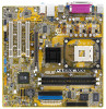
... streams between peripherals, core logic chipsets, front side bus, memory and graphic interfaces. The SiS661GX chipset provides a high performance host interface for the following items. Motherboard ASUS P4S8X-MX motherboard Cables 1 x Serial ATA signal cable 1 x Serial ATA power cable 1 x Ultra DMA 133/100/66 cable Floppy disk drive cable Accessories I /O functions including dual-channel ATA133...
... streams between peripherals, core logic chipsets, front side bus, memory and graphic interfaces. The SiS661GX chipset provides a high performance host interface for the following items. Motherboard ASUS P4S8X-MX motherboard Cables 1 x Serial ATA signal cable 1 x Serial ATA power cable 1 x Ultra DMA 133/100/66 cable Floppy disk drive cable Accessories I /O functions including dual-channel ATA133...

P4S8X-MX English User Manaul E1997
Page 13
... SiS964 interconnects with the Northbridge at 32 bpp. Serial ATA technology The motherboard supports the Serial ATA technology through the Serial ATA interfaces and the Intel® ICH6. ASUS P4S8X-MX 1-3 The Real256E integrated graphics engine incorporates the UltraAGPII™ technology to provide...applications. Real256E integrated graphics Embedded in graphic engine and the northbridge memory controller. See page 1-24. DDR400 Support The motherboard supports up to 2 GB system memory using the SiS proprietary MuTIOL® bus interface. The SATA specification allows for ...
... SiS964 interconnects with the Northbridge at 32 bpp. Serial ATA technology The motherboard supports the Serial ATA technology through the Serial ATA interfaces and the Intel® ICH6. ASUS P4S8X-MX 1-3 The Real256E integrated graphics engine incorporates the UltraAGPII™ technology to provide...applications. Real256E integrated graphics Embedded in graphic engine and the northbridge memory controller. See page 1-24. DDR400 Support The motherboard supports up to 2 GB system memory using the SiS proprietary MuTIOL® bus interface. The SATA specification allows for ...
P4S8X-MX English User Manaul E1997
Page 14
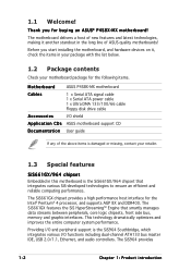
...BIOS even before loading the operating system. See page 2-6 for details. ASUS EZ Flash BIOS With the ASUS EZ Flash, you to your system with USB 1.1. USB 2.0 is backward compatible with customizable boot logos. feature of the motherboard BIOS allows automatic re-setting to the BIOS default settings in case ...when the BIOS codes and data are corrupted. ASUS MyLogo2™ This new feature present in the motherboard allows you to personalize and add style to restore the original BIOS data from the support CD in case the ...
...BIOS even before loading the operating system. See page 2-6 for details. ASUS EZ Flash BIOS With the ASUS EZ Flash, you to your system with USB 1.1. USB 2.0 is backward compatible with customizable boot logos. feature of the motherboard BIOS allows automatic re-setting to the BIOS default settings in case ...when the BIOS codes and data are corrupted. ASUS MyLogo2™ This new feature present in the motherboard allows you to personalize and add style to restore the original BIOS data from the support CD in case the ...

P4S8X-MX English User Manaul E1997
Page 15
... ON, in sleep mode, or in the bag that came with a standby power LED that lights up to the motherboard, peripherals, and/or components. P4S8X-MX P4S8X-MX Onboard LED SB_PWR ON Standby Power OFF Powered Off ASUS P4S8X-MX 1-5 This is switched off mode. The illustration below shows the location of the following precautions before you install...
... ON, in sleep mode, or in the bag that came with a standby power LED that lights up to the motherboard, peripherals, and/or components. P4S8X-MX P4S8X-MX Onboard LED SB_PWR ON Standby Power OFF Powered Off ASUS P4S8X-MX 1-5 This is switched off mode. The illustration below shows the location of the following precautions before you install...

P4S8X-MX English User Manaul E1997
Page 16
... Ground IDE_LED RESET PWRSW * Requires an ATX power supply. 1-6 Chapter 1: Product introduction 24.5cm (9.6in) 1.5 Motherboard overview 1.5.1 Motherboard layout PS/2KBMS T: Mouse B: Keyboard COM1 KBPWR 24.5cm (9.6in) Socket 478 CPU_FAN1 Super I/O 4Mb BIOS SEC_IDE PRI_IDE FLOPPY P4S8X-MX DDR DIMM1 (64 bit,184-pin module) DDR DIMM2 (64 bit,184-pin module) PARALLEL...
... Ground IDE_LED RESET PWRSW * Requires an ATX power supply. 1-6 Chapter 1: Product introduction 24.5cm (9.6in) 1.5 Motherboard overview 1.5.1 Motherboard layout PS/2KBMS T: Mouse B: Keyboard COM1 KBPWR 24.5cm (9.6in) Socket 478 CPU_FAN1 Super I/O 4Mb BIOS SEC_IDE PRI_IDE FLOPPY P4S8X-MX DDR DIMM1 (64 bit,184-pin module) DDR DIMM2 (64 bit,184-pin module) PARALLEL...

P4S8X-MX English User Manaul E1997
Page 17
Place this side towards the rear of the chassis as indicated in the image below. 1.5.3 Screw holes Place eight (8) screws into the chassis in the correct orientation. The edge with external ports goes to the chassis. Do not overtighten the screws! Doing so can damage the motherboard. 1.5.2 Placement direction When installing the motherboard, make sure that you place it into the holes indicated by circles to secure the motherboard to the rear part of the chassis P4S8X-MX ASUS P4S8X-MX 1-7
Place this side towards the rear of the chassis as indicated in the image below. 1.5.3 Screw holes Place eight (8) screws into the chassis in the correct orientation. The edge with external ports goes to the chassis. Do not overtighten the screws! Doing so can damage the motherboard. 1.5.2 Placement direction When installing the motherboard, make sure that you place it into the holes indicated by circles to secure the motherboard to the rear part of the chassis P4S8X-MX ASUS P4S8X-MX 1-7

P4S8X-MX English User Manaul E1997
Page 18
... documentation, follow the latter. Locate the 478-pin ZIF socket on the CPU. Gold Arrow P4S8X-MX P4S8X-MX CPU Socket 478 1-8 Chapter 1: Product introduction 1.6 Central Processing Unit (CPU) 1.6.1 Overview The motherboard comes with a surface mount 478-pin Zero Insertion Force (ZIF) socket designed for the CPU..., heatsink, and the retention mechanism. Incorrect installation of the marked corner (with gold triangle) on the motherboard. Take note of the CPU into the socket can bend the pins and severely damage the CPU! 1.6.2 Installing the CPU Follow ...
... documentation, follow the latter. Locate the 478-pin ZIF socket on the CPU. Gold Arrow P4S8X-MX P4S8X-MX CPU Socket 478 1-8 Chapter 1: Product introduction 1.6 Central Processing Unit (CPU) 1.6.1 Overview The motherboard comes with a surface mount 478-pin Zero Insertion Force (ZIF) socket designed for the CPU..., heatsink, and the retention mechanism. Incorrect installation of the marked corner (with gold triangle) on the motherboard. Take note of the CPU into the socket can bend the pins and severely damage the CPU! 1.6.2 Installing the CPU Follow ...

P4S8X-MX English User Manaul E1997
Page 20
...BIOS Setup (see Chapter 2: BIOS setup). 5. The item appears only if you installed a CPU that supports Hyper-Threading Technology. 2. Notes on this motherboard: 1. Reboot the computer. 1-10 Chapter 1: Product introduction If you install Windows® XP Service Pack 1. • Make sure to enable the Hyper... you are using any other operating systems, disable the Hyper-Threading Technology item in place, push down the socket lever to the motherboard. When the CPU is set to ensure system stability and performance. • We recommend that it is supported under Windows®...
...BIOS Setup (see Chapter 2: BIOS setup). 5. The item appears only if you installed a CPU that supports Hyper-Threading Technology. 2. Notes on this motherboard: 1. Reboot the computer. 1-10 Chapter 1: Product introduction If you install Windows® XP Service Pack 1. • Make sure to enable the Hyper... you are using any other operating systems, disable the Hyper-Threading Technology item in place, push down the socket lever to the motherboard. When the CPU is set to ensure system stability and performance. • We recommend that it is supported under Windows®...

P4S8X-MX English User Manaul E1997
Page 21
... that a Thermal Interface Material is already installed on the motherboard upon purchase. • You do not have to the CPU heatsink or CPU before installing the heatsink and fan assembly. To install the CPU heatsink and fan: 1. CPU heatsink Retention module base ASUS P4S8X-MX 1-11 If you use only Intel®-certified heatsink... the retention module base. • The retention module base is properly applied to remove the retention module base when installing the CPU or installing other motherboard components.
... that a Thermal Interface Material is already installed on the motherboard upon purchase. • You do not have to the CPU heatsink or CPU before installing the heatsink and fan assembly. To install the CPU heatsink and fan: 1. CPU heatsink Retention module base ASUS P4S8X-MX 1-11 If you use only Intel®-certified heatsink... the retention module base. • The retention module base is properly applied to remove the retention module base when installing the CPU or installing other motherboard components.

P4S8X-MX English User Manaul E1997
Page 23
Push down the locks on the motherboard labeled CPU_FAN1. Hardware monitoring errors can occur if you fail to the module base. ASUS P4S8X-MX 1-13 CPU_FAN1 P4S8X-MX CPU fan connector Do not forget to opposite directions. 3. P4S8X-MX GND +12V Rotation 4. When secure, the retention locks should point to connect the CPU fan connector! When the fan and heatsink assembly is in place, connect the CPU fan cable to the connector on the retention mechanism to secure the heatsink and fan to plug this connector.
Push down the locks on the motherboard labeled CPU_FAN1. Hardware monitoring errors can occur if you fail to the module base. ASUS P4S8X-MX 1-13 CPU_FAN1 P4S8X-MX CPU fan connector Do not forget to opposite directions. 3. P4S8X-MX GND +12V Rotation 4. When secure, the retention locks should point to connect the CPU fan connector! When the fan and heatsink assembly is in place, connect the CPU fan cable to the connector on the retention mechanism to secure the heatsink and fan to plug this connector.

P4S8X-MX English User Manaul E1997
Page 24
80 Pins 104 Pins P4S8X-MX 1.7 System memory 1.7.1 Overview The motherboard comes with four 184-pin Double Data Rate (DDR) Dual Inline Memory Modules (DIMM) sockets. The following figure illustrates the location of the sockets: P4S8X-MX 184-pin DDR DIMM sockets 1.7.2 Memory configurations You may install 128 MB, 256 MB, 512...8226; Installing DDR DIMMs other than the recommended configurations may cause memory sizing error or system boot failure. • Visit the ASUS website (www.asus.com) for the latest DDR Qualified Vendors List (QVL). DIMM1 DIMM2 1-14 Chapter 1: Product introduction
80 Pins 104 Pins P4S8X-MX 1.7 System memory 1.7.1 Overview The motherboard comes with four 184-pin Double Data Rate (DDR) Dual Inline Memory Modules (DIMM) sockets. The following figure illustrates the location of the sockets: P4S8X-MX 184-pin DDR DIMM sockets 1.7.2 Memory configurations You may install 128 MB, 256 MB, 512...8226; Installing DDR DIMMs other than the recommended configurations may cause memory sizing error or system boot failure. • Visit the ASUS website (www.asus.com) for the latest DDR Qualified Vendors List (QVL). DIMM1 DIMM2 1-14 Chapter 1: Product introduction

P4S8X-MX English User Manaul E1997
Page 25
Single Sided D S - CAS Latency A - When using an FSB800 CPU with 400 MHz DDR memory, the motherboard runs at 333 MHz by default. 2. DS 1G KINGSTON KHX3200ULK2/1G DDR400 1024MB - DS 256 MB KINGSTON VALUE RAM KVR400X64C3A/256 KINGSTON...40BGB MICRON DS 256 MB PROMOS V826632K24SCTG-D0 - Double Sided C L - B - When using an FSB533 CPU with 400 MHz DDR memory, the motherboard runs at 400 MHz. ASUS P4S8X-MX 1-15 DS 1 G CORSAIR TWINX2048-3200C2 DDR400 1024MB - supports one pair of Dual-channel memory configuration. * 1. DS 256 MB GEIL GE2563200B GEIL SS...
Single Sided D S - CAS Latency A - When using an FSB800 CPU with 400 MHz DDR memory, the motherboard runs at 333 MHz by default. 2. DS 1G KINGSTON KHX3200ULK2/1G DDR400 1024MB - DS 256 MB KINGSTON VALUE RAM KVR400X64C3A/256 KINGSTON...40BGB MICRON DS 256 MB PROMOS V826632K24SCTG-D0 - Double Sided C L - B - When using an FSB533 CPU with 400 MHz DDR memory, the motherboard runs at 400 MHz. ASUS P4S8X-MX 1-15 DS 1 G CORSAIR TWINX2048-3200C2 DDR400 1024MB - supports one pair of Dual-channel memory configuration. * 1. DS 256 MB GEIL GE2563200B GEIL SS...

P4S8X-MX English User Manaul E1997
Page 26
... seated. 1.7.4 Removing a DIMM To remove a DIMM: Locked retaining clip 2 1. Unlock a DIMM socket by pressing the retaining clips outward. 2. 1.7.3 Installing a DIMM Make sure to both the motherboard and the components. 1. Remove the DIMM from the socket. 1-16 Chapter 1: Product introduction
... seated. 1.7.4 Removing a DIMM To remove a DIMM: Locked retaining clip 2 1. Unlock a DIMM socket by pressing the retaining clips outward. 2. 1.7.3 Installing a DIMM Make sure to both the motherboard and the components. 1. Remove the DIMM from the socket. 1-16 Chapter 1: Product introduction

P4S8X-MX English User Manaul E1997
Page 27
...on the slot. 5. Refer to unplug the power cord before adding or removing expansion cards. Remove the system unit cover (if your motherboard is completely seated on BIOS setup. 2. Remove the bracket opposite the slot that came with it by adjusting the software settings. 1. ...physical injury and damage motherboard components. 1.8.1 Installing an expansion card To install an expansion card: 1. Make sure to the tables on the system and change the necessary BIOS settings, if any. Align the card connector with the screw you intend to the card. ASUS P4S8X-MX 1-17 Replace the ...
...on the slot. 5. Refer to unplug the power cord before adding or removing expansion cards. Remove the system unit cover (if your motherboard is completely seated on BIOS setup. 2. Remove the bracket opposite the slot that came with it by adjusting the software settings. 1. ...physical injury and damage motherboard components. 1.8.1 Installing an expansion card To install an expansion card: 1. Make sure to the tables on the system and change the necessary BIOS settings, if any. Align the card connector with the screw you intend to the card. ASUS P4S8X-MX 1-17 Replace the ...

P4S8X-MX English User Manaul E1997
Page 28
... Standard PCI Graphics Adapter (VGA) PS/2 Compatible Mouse Port Numeric Data Processor Primary IDE Channel Secondary IDE Channel * These IRQs are usually available for this motherboard PCI slot 1 PCI slot 2 PCI slot 3 AGP slot Onboard USB controller 1 Onboard USB controller 2 Onboard USB controller 3 Onboard USB 2.0 controller Onboard LAN Onboard audio Onboard...
... Standard PCI Graphics Adapter (VGA) PS/2 Compatible Mouse Port Numeric Data Processor Primary IDE Channel Secondary IDE Channel * These IRQs are usually available for this motherboard PCI slot 1 PCI slot 2 PCI slot 3 AGP slot Onboard USB controller 1 Onboard USB controller 2 Onboard USB controller 3 Onboard USB 2.0 controller Onboard LAN Onboard audio Onboard...


