
Motherboard DIY Troubleshooting Guide
Page 2
... USB3 USB4 Top: RJ-45 ATX12V1 Top:Line In Center:Line Out Below:Mic In Realtek RTL8201 SiS645 HOST/ Memory Controller Accelerated Graphics Port (AGP) Audio Codec CHA_FAN1 FP_AUDIO1 CD1 AUX1 PCI Slot 1 PCI Slot 2 SB_PWR1 PCI Slot 3 ...PCI Slot 4 ® PCI Slot 5 P4S-X PCI Slot 6 USB56 01 23 CR2032 3V Lithium Cell CMOS Power SiS962L MuTLOL Media I/0 CLRTC1 GAME1 2Mbit Flash BIOS COM2... de reset Commutateur d'alimentation ATX* * Nécessite une alimentation ATX. 2 Carte mère ASUS P4S-X Français 1.
... USB3 USB4 Top: RJ-45 ATX12V1 Top:Line In Center:Line Out Below:Mic In Realtek RTL8201 SiS645 HOST/ Memory Controller Accelerated Graphics Port (AGP) Audio Codec CHA_FAN1 FP_AUDIO1 CD1 AUX1 PCI Slot 1 PCI Slot 2 SB_PWR1 PCI Slot 3 ...PCI Slot 4 ® PCI Slot 5 P4S-X PCI Slot 6 USB56 01 23 CR2032 3V Lithium Cell CMOS Power SiS962L MuTLOL Media I/0 CLRTC1 GAME1 2Mbit Flash BIOS COM2... de reset Commutateur d'alimentation ATX* * Nécessite une alimentation ATX. 2 Carte mère ASUS P4S-X Français 1.

Motherboard DIY Troubleshooting Guide
Page 5
... PORT COM1 USB12 Bottom: USB3 USB4 Top: RJ-45 ATX12V1 Top:Line In Center:Line Out Below:Mic In Realtek RTL8201 SiS645 HOST/ Memory Controller Accelerated Graphics Port (AGP) Audio Codec CHA_FAN1 FP_AUDIO1 CD1 AUX1 PCI Slot 1 PCI Slot 2 SB_PWR1 PCI Slot 3 PCI Slot 4 ® PCI ... Ground Speaker +5V IDELED ExtSMI# Ground PWR Ground Reset Ground IDE-LED SMI-Leiter Reset-Schalter ATX-Stromschalter* * Benötigt ATX-Stromversorgung. ASUS P4S-X-Motherboard 5 Socket 478 DDR DIMM1 (64/72 bit, 184-pin module) DDR DIMM2 (64/72 bit, 184-pin module) SEC_IDE1 PRI_IDE1 Deutsch 1.
... PORT COM1 USB12 Bottom: USB3 USB4 Top: RJ-45 ATX12V1 Top:Line In Center:Line Out Below:Mic In Realtek RTL8201 SiS645 HOST/ Memory Controller Accelerated Graphics Port (AGP) Audio Codec CHA_FAN1 FP_AUDIO1 CD1 AUX1 PCI Slot 1 PCI Slot 2 SB_PWR1 PCI Slot 3 PCI Slot 4 ® PCI ... Ground Speaker +5V IDELED ExtSMI# Ground PWR Ground Reset Ground IDE-LED SMI-Leiter Reset-Schalter ATX-Stromschalter* * Benötigt ATX-Stromversorgung. ASUS P4S-X-Motherboard 5 Socket 478 DDR DIMM1 (64/72 bit, 184-pin module) DDR DIMM2 (64/72 bit, 184-pin module) SEC_IDE1 PRI_IDE1 Deutsch 1.

Motherboard DIY Troubleshooting Guide
Page 11
...: USB3 USB4 Top: RJ-45 ATX12V1 Top:Line In Center:Line Out Below:Mic In Realtek RTL8201 SiS645 HOST/ Memory Controller Accelerated Graphics Port (AGP) Audio Codec CHA_FAN1 FP_AUDIO1 CD1 AUX1 PCI Slot 1 PCI Slot 2 SB_PWR1 PCI Slot 3 PCI ...Slot 4 ® PCI Slot 5 P4S-X PCI Slot 6 USB56 01 23 CR2032 3V Lithium Cell CMOS Power SiS962L MuTLOL Media I/0 CLRTC1 GAME1 2Mbit Flash BIOS COM2 Super...ón ATX* * Necesita una fuente de alimentación ATX. Español Placa base ASUS P4S-X 11 1.
...: USB3 USB4 Top: RJ-45 ATX12V1 Top:Line In Center:Line Out Below:Mic In Realtek RTL8201 SiS645 HOST/ Memory Controller Accelerated Graphics Port (AGP) Audio Codec CHA_FAN1 FP_AUDIO1 CD1 AUX1 PCI Slot 1 PCI Slot 2 SB_PWR1 PCI Slot 3 PCI ...Slot 4 ® PCI Slot 5 P4S-X PCI Slot 6 USB56 01 23 CR2032 3V Lithium Cell CMOS Power SiS962L MuTLOL Media I/0 CLRTC1 GAME1 2Mbit Flash BIOS COM2 Super...ón ATX* * Necesita una fuente de alimentación ATX. Español Placa base ASUS P4S-X 11 1.

Motherboard DIY Troubleshooting Guide
Page 14
... USB3 USB4 Top: RJ-45 ATX12V1 Top:Line In Center:Line Out Below:Mic In Realtek RTL8201 SiS645 HOST/ Memory Controller Accelerated Graphics Port (AGP) Audio Codec CHA_FAN1 FP_AUDIO1 CD1 AUX1 PCI Slot 1 PCI Slot 2 SB_PWR1 PCI Slot 3 PCI ...Slot 4 ® PCI Slot 5 P4S-X PCI Slot 6 USB56 01 23 CR2032 3V Lithium Cell CMOS Power SiS962L MuTLOL Media I/0 CLRTC1 GAME1 2Mbit Flash BIOS COM2 ...PWR Ground Reset Ground IDE_LED SMI ATX* ATX. усский 14 ASUS P4S-X
... USB3 USB4 Top: RJ-45 ATX12V1 Top:Line In Center:Line Out Below:Mic In Realtek RTL8201 SiS645 HOST/ Memory Controller Accelerated Graphics Port (AGP) Audio Codec CHA_FAN1 FP_AUDIO1 CD1 AUX1 PCI Slot 1 PCI Slot 2 SB_PWR1 PCI Slot 3 PCI ...Slot 4 ® PCI Slot 5 P4S-X PCI Slot 6 USB56 01 23 CR2032 3V Lithium Cell CMOS Power SiS962L MuTLOL Media I/0 CLRTC1 GAME1 2Mbit Flash BIOS COM2 ...PWR Ground Reset Ground IDE_LED SMI ATX* ATX. усский 14 ASUS P4S-X
P4S-X User Manual
Page 3
... information vi About this guide vii ASUS contact information viii P4S-X specifications summary ix Chapter 1: Product introduction 1.1 Welcome 1-2 1.2 Package contents 1-2 1.3 Motherboard components 1-3 1.4 Special Features 1-6 1.5 Motherboard layout 1-7 1.6 Before you proceed 1-8 1.7 Motherboard installation 1-9 1.7.1 Placement direction 1-9 1.7.2 Screw holes 1-9 1.8 Central Processing Unit (CPU 1-10 1.8.1 Overview 1-11 1.8.2 Installing the CPU 1-11 1.9 System memory 1-12 1.10 Expansion slots 1-13...
... information vi About this guide vii ASUS contact information viii P4S-X specifications summary ix Chapter 1: Product introduction 1.1 Welcome 1-2 1.2 Package contents 1-2 1.3 Motherboard components 1-3 1.4 Special Features 1-6 1.5 Motherboard layout 1-7 1.6 Before you proceed 1-8 1.7 Motherboard installation 1-9 1.7.1 Placement direction 1-9 1.7.2 Screw holes 1-9 1.8 Central Processing Unit (CPU 1-10 1.8.1 Overview 1-11 1.8.2 Installing the CPU 1-11 1.9 System memory 1-12 1.10 Expansion slots 1-13...
P4S-X User Manual
Page 9
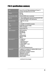
... (1.5V only) 6 x PCI 2 x UltraDMA 133/100/66/33 connectors ADI AD1980 6-channel CODEC S/PDIF out interface Realtek 8201BL PHY ASUS JumperFree ASUS MyLogo ASUS EZ Flash C.P.R. P4S-X specifications summary CPU Chipset Front Side Bus (FSB) Memory Expansion slots IDE Audio LAN Special features Rear panel I/O Internal I/O Socket 478 for Intel® Willamette/Northwood Pentium®...
... (1.5V only) 6 x PCI 2 x UltraDMA 133/100/66/33 connectors ADI AD1980 6-channel CODEC S/PDIF out interface Realtek 8201BL PHY ASUS JumperFree ASUS MyLogo ASUS EZ Flash C.P.R. P4S-X specifications summary CPU Chipset Front Side Bus (FSB) Memory Expansion slots IDE Audio LAN Special features Rear panel I/O Internal I/O Socket 478 for Intel® Willamette/Northwood Pentium®...
P4S-X User Manual
Page 12
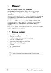
...Processor in 478-pin package coupled with the list below. 1.2 Package contents Check your P4S-X package for the following items. ASUS P4S-X motherboard ATX form factor: 12 in x 9.6 in (30.5 cm x 24.5 cm) ASUS P4S-X series support CD 80-conductor UltraDMA33/66/100/133 IDE cable Ribbon cable for a ...Supporting up to 2GB of system memory with the PC2700/2100/1600 DDR DIMMs, high-resolution graphics via an AGP 4X slot, USB 2.0, and 6-channel audio features, the P4S-X is damaged or missing, contact your retailer. 1-2 Chapter 1: Product introduction The ASUS P4S-X motherboard delivers a host of ...
...Processor in 478-pin package coupled with the list below. 1.2 Package contents Check your P4S-X package for the following items. ASUS P4S-X motherboard ATX form factor: 12 in x 9.6 in (30.5 cm x 24.5 cm) ASUS P4S-X series support CD 80-conductor UltraDMA33/66/100/133 IDE cable Ribbon cable for a ...Supporting up to 2GB of system memory with the PC2700/2100/1600 DDR DIMMs, high-resolution graphics via an AGP 4X slot, USB 2.0, and 6-channel audio features, the P4S-X is damaged or missing, contact your retailer. 1-2 Chapter 1: Product introduction The ASUS P4S-X motherboard delivers a host of ...

P4S-X User Manual
Page 14
...power supply. This Low Pin Count (LPC) interface provides the commonly used Super I /O controller. This LED lights up to 2GB system memory using unbuffered non-ECC PC2700/PC2100/PC1600 DDR DIMMs. 6 IDE connectors. This SiS645 controller integrates a high performance host interface for 5.1 surround... greater than 90dB dynamic range support. 15 AGP slot. The audio CODEC provides six DAC channels for the Intel Pentium 4 processor, a memory controller and SiS MuTIOL technology. 4 ATX power connector. This Accelerated Graphics Port (AGP) slot supports 1.5V AGP4X mode graphics cards for...
...power supply. This Low Pin Count (LPC) interface provides the commonly used Super I /O controller. This LED lights up to 2GB system memory using unbuffered non-ECC PC2700/PC2100/PC1600 DDR DIMMs. 6 IDE connectors. This SiS645 controller integrates a high performance host interface for 5.1 surround... greater than 90dB dynamic range support. 15 AGP slot. The audio CODEC provides six DAC channels for the Intel Pentium 4 processor, a memory controller and SiS MuTIOL technology. 4 ATX power connector. This Accelerated Graphics Port (AGP) slot supports 1.5V AGP4X mode graphics cards for...
P4S-X User Manual
Page 17
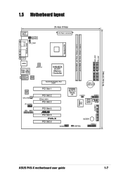
... PARALLEL PORT COM1 USB12 Bottom: USB3 USB4 Top: RJ-45 ATX12V1 Top:Line In Center:Line Out Below:Mic In Realtek RTL8201 SiS645DX HOST/ Memory Controller Accelerated Graphics Port (AGP) Audio Codec CHA_FAN1 FP_AUDIO1 CD1 AUX1 PCI Slot 1 PCI Slot 2 SB_PWR1 PCI Slot 3 PCI Slot 4 ® PCI... Slot 5 P4S-X PCI Slot 6 USB56 01 23 CR2032 3V Lithium Cell CMOS Power SiS962L MuTLOL Media I/0 CLRTC1 GAME1 2Mbit Flash BIOS COM2 Super I/O FLOPPY1 BUZZER1 USBPW56 ...
... PARALLEL PORT COM1 USB12 Bottom: USB3 USB4 Top: RJ-45 ATX12V1 Top:Line In Center:Line Out Below:Mic In Realtek RTL8201 SiS645DX HOST/ Memory Controller Accelerated Graphics Port (AGP) Audio Codec CHA_FAN1 FP_AUDIO1 CD1 AUX1 PCI Slot 1 PCI Slot 2 SB_PWR1 PCI Slot 3 PCI Slot 4 ® PCI... Slot 5 P4S-X PCI Slot 6 USB56 01 23 CR2032 3V Lithium Cell CMOS Power SiS962L MuTLOL Media I/0 CLRTC1 GAME1 2Mbit Flash BIOS COM2 Super I/O FLOPPY1 BUZZER1 USBPW56 ...

P4S-X User Manual
Page 22
... Firmly insert the DIMM into the socket until the retaining clips snap back in place and the DIMM is double notched. 104 Pins ® P4S-X P4S-X 184-Pin DDR DIMM Sockets 80 Pins 1. Failure to do so may cause severe damage to the motherboard and other system components. Align a... DIMM on the socket. 3. DDR DIMM notch 1. 1.9 System memory The motherboard has two Double Data Rate (DDR) DIMM sockets that the notch on the DIMM matches the break on the socket such that supports...
... Firmly insert the DIMM into the socket until the retaining clips snap back in place and the DIMM is double notched. 104 Pins ® P4S-X P4S-X 184-Pin DDR DIMM Sockets 80 Pins 1. Failure to do so may cause severe damage to the motherboard and other system components. Align a... DIMM on the socket. 3. DDR DIMM notch 1. 1.9 System memory The motherboard has two Double Data Rate (DDR) DIMM sockets that the notch on the DIMM matches the break on the socket such that supports...
P4S-X User Manual
Page 25
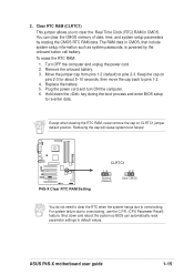
...erasing the CMOS RTC RAM data. To erase the RTC RAM: 1. Replace the battery. 5. Removing the cap will cause system boot failure! ® P4S-X P4S-X Clear RTC RAM Setting CLRTC1 12 Normal (Default) 23 Clear CMOS You do not need to clear the RTC when the system hangs due to...on CLRTC1 jumper default position. For system failure due to pins 1-2. 4. ASUS P4S-X motherboard user guide 1-15 Turn OFF the computer and unplug the power cord. 2. Hold down and reboot the system so BIOS can clear the CMOS memory of date, time, and system setup parameters by the onboard button cell ...
...erasing the CMOS RTC RAM data. To erase the RTC RAM: 1. Replace the battery. 5. Removing the cap will cause system boot failure! ® P4S-X P4S-X Clear RTC RAM Setting CLRTC1 12 Normal (Default) 23 Clear CMOS You do not need to clear the RTC when the system hangs due to...on CLRTC1 jumper default position. For system failure due to pins 1-2. 4. ASUS P4S-X motherboard user guide 1-15 Turn OFF the computer and unplug the power cord. 2. Hold down and reboot the system so BIOS can clear the CMOS memory of date, time, and system setup parameters by the onboard button cell ...
P4S-X User Manual
Page 35
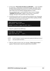
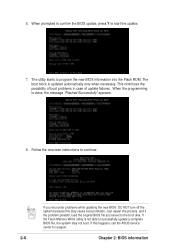
... the correct file name. At the above prompt, type Y to continue with the new BIOS. Doing so may cause system boot failure. 8. ASUS P4S-X motherboard user guide 2-3 When found ." The following message appears on screen. If you accidentally typed in the BIOS file name that you downloaded ...from the ASUS website, then press . Press Y to remove the message, then type in File] BIOS Version: P4S-X Boot Block WARNING! Press to update the main BIOS area. Flash Memory: SST 49LF004 Update Main BIOS area (Y/N)? _ DO NOT ...
... the correct file name. At the above prompt, type Y to continue with the new BIOS. Doing so may cause system boot failure. 8. ASUS P4S-X motherboard user guide 2-3 When found ." The following message appears on screen. If you accidentally typed in the BIOS file name that you downloaded ...from the ASUS website, then press . Press Y to remove the message, then type in File] BIOS Version: P4S-X Boot Block WARNING! Press to update the main BIOS area. Flash Memory: SST 49LF004 Update Main BIOS area (Y/N)? _ DO NOT ...
P4S-X User Manual
Page 36
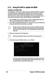
... item in DOS mode. This file works only in the DOS prompt within Windows, and does not work with certain memory drivers that updates the BIOS by the Flash Memory Writer utility. 2-4 Chapter 2: BIOS information 2.1.2 Using AFLASH to update the BIOS Creating a bootable disk AFLASH.EXE is... disk. 3. Type COPY D:\AFLASH\AFLASH.EXE A:\ (assuming D is your screen during bootup. If the word "unknown" appears after Flash Memory:, the memory chip is either not programmable or is recommended that you boot from the floppy disk. To determine the BIOS version of your motherboard, check ...
... item in DOS mode. This file works only in the DOS prompt within Windows, and does not work with certain memory drivers that updates the BIOS by the Flash Memory Writer utility. 2-4 Chapter 2: BIOS information 2.1.2 Using AFLASH to update the BIOS Creating a bootable disk AFLASH.EXE is... disk. 3. Type COPY D:\AFLASH\AFLASH.EXE A:\ (assuming D is your screen during bootup. If the word "unknown" appears after Flash Memory:, the memory chip is either not programmable or is recommended that you boot from the floppy disk. To determine the BIOS version of your motherboard, check ...
P4S-X User Manual
Page 38
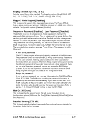
If the Flash Memory Writer utility is done, the message "Flashed Successfully" appears. 8. This minimizes the possibility of boot problems in case of update failures. When the programming is ... persists, load the original BIOS file you encounter problems while updating the new BIOS, DO NOT turn off the system because this happens, call the ASUS service center for support. 2-6 Chapter 2: BIOS information Follow the onscreen instructions to start the update. 7. If you saved to program the new BIOS information into...
If the Flash Memory Writer utility is done, the message "Flashed Successfully" appears. 8. This minimizes the possibility of boot problems in case of update failures. When the programming is ... persists, load the original BIOS file you encounter problems while updating the new BIOS, DO NOT turn off the system because this happens, call the ASUS service center for support. 2-6 Chapter 2: BIOS information Follow the onscreen instructions to start the update. 7. If you saved to program the new BIOS information into...
P4S-X User Manual
Page 43
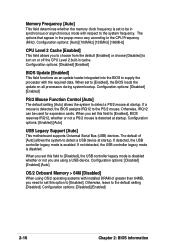
... If you did , the Supervisor password is required to enter the BIOS Setup program and to gain full access to the configuration fields. ASUS P4S-X motherboard user guide 2-11 The Floppy 3 Mode feature allows reading and writing of floppy drive installed. To clear the password, highlight this ... The RAM data containing the password information is now set to [Enabled]. Halt On [All Errors] This field specifies the types of conventional memory detected by erasing the CMOS Real Time Clock (RTC) RAM. Symbols and other characters are not case sensitive, meaning, passwords typed in ...
... If you did , the Supervisor password is required to enter the BIOS Setup program and to gain full access to the configuration fields. ASUS P4S-X motherboard user guide 2-11 The Floppy 3 Mode feature allows reading and writing of floppy drive installed. To clear the password, highlight this ... The RAM data containing the password information is now set to [Enabled]. Halt On [All Errors] This field specifies the types of conventional memory detected by erasing the CMOS Real Time Clock (RTC) RAM. Symbols and other characters are not case sensitive, meaning, passwords typed in ...
P4S-X User Manual
Page 48
... system to [Enabled]. If not detected, the USB controller legacy mode is detected at startup. Configuration options: [Disabled] [Enabled] [Auto] OS/2 Onboard Memory > 64M [Disabled] When using a USB device. When you need to set this option to detect a PS/2 mouse at startup. If detected, the ...field to [Disabled], the USB controller legacy mode is enabled. When set to be used for expansion cards. Memory Frequency [Auto] This field determines whether the memory clock frequency is detected, the BIOS assigns IRQ12 to the PS/2 mouse. The options that appear in synchronous or...
... system to [Enabled]. If not detected, the USB controller legacy mode is detected at startup. Configuration options: [Disabled] [Enabled] [Auto] OS/2 Onboard Memory > 64M [Disabled] When using a USB device. When you need to set this option to detect a PS/2 mouse at startup. If detected, the ...field to [Disabled], the USB controller legacy mode is enabled. When set to be used for expansion cards. Memory Frequency [Auto] This field determines whether the memory clock frequency is detected, the BIOS assigns IRQ12 to the PS/2 mouse. The options that appear in synchronous or...

P4S-X User Manual
Page 49
...actually becomes available. SDRAM CAS Latency (value depends on the memory modules that you set the SDRAM Configuration to [User Defined]. Configuration options: [6T] [7T] [5T] [4T] SDRAM Command Lead-off Time [Auto] Configuration options: [Auto] [2T] [1T] ASUS P4S-X motherboard user guide 2-17 The default setting is [By ... issuing a precharge command to the DDR SDRAM. Configuration options: [3T] [2T] [4T] SDRAM RAS Precharge Time (value depends on the memory module stores critical information about the module, such as memory type, size, speed, voltage interface, and module banks.
...actually becomes available. SDRAM CAS Latency (value depends on the memory modules that you set the SDRAM Configuration to [User Defined]. Configuration options: [6T] [7T] [5T] [4T] SDRAM Command Lead-off Time [Auto] Configuration options: [Auto] [2T] [1T] ASUS P4S-X motherboard user guide 2-17 The default setting is [By ... issuing a precharge command to the DDR SDRAM. Configuration options: [3T] [2T] [4T] SDRAM RAS Precharge Time (value depends on the memory module stores critical information about the module, such as memory type, size, speed, voltage interface, and module banks.

P4S-X User Manual
Page 50
... Write Capability [Enabled] This field enables or disables the AGP 4x Fast Write Capability feature. Configuration options: [Disabled] [Enabled] Video Memory Cache Mode [UC] USWC (uncacheable, speculative write combining) is backward-compatible, so you may not boot. Graphics Aperture Size [64MB...data. You can greatly improve the display speed by caching the display data. AGP 4X is a new cache technology for the video memory of mapped memory for non-Windows operating systems. Configuration options: [Disabled] [Enabled] 2-18 Chapter 2: BIOS information Configuration options: [UC] [USWC...
... Write Capability [Enabled] This field enables or disables the AGP 4x Fast Write Capability feature. Configuration options: [Disabled] [Enabled] Video Memory Cache Mode [UC] USWC (uncacheable, speculative write combining) is backward-compatible, so you may not boot. Graphics Aperture Size [64MB...data. You can greatly improve the display speed by caching the display data. AGP 4X is a new cache technology for the video memory of mapped memory for non-Windows operating systems. Configuration options: [Disabled] [Enabled] 2-18 Chapter 2: BIOS information Configuration options: [UC] [USWC...


