
P4PE-X/TE User Manual
Page 12
... making it , check the items in your package with the list below. *Overclocking mode 1.2 Package contents Check your P4PE-X/TE package for the following items. ASUS P4PE-X/TE motherboard ATX form factor: 12 in x 9 in 478-pin package coupled with the Intel® 845PE chipset to ...line of computing! See page 1-10 for buying the ASUS® P4PE-X/TE motherboard! Before you for more information. 1-2 Chapter 1: Product introduction The motherboard incorporates the Intel® Pentium® 4 Processor in (30.5 cm x 22.9 cm) ASUS P4PE-X/TE series support CD 1 x 80-conductor ribbon cables ...
... making it , check the items in your package with the list below. *Overclocking mode 1.2 Package contents Check your P4PE-X/TE package for the following items. ASUS P4PE-X/TE motherboard ATX form factor: 12 in x 9 in 478-pin package coupled with the Intel® 845PE chipset to ...line of computing! See page 1-10 for buying the ASUS® P4PE-X/TE motherboard! Before you for more information. 1-2 Chapter 1: Product introduction The motherboard incorporates the Intel® Pentium® 4 Processor in (30.5 cm x 22.9 cm) ASUS P4PE-X/TE series support CD 1 x 80-conductor ribbon cables ...
P4PE-X/TE User Manual
Page 13
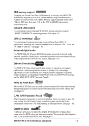
... eliminates the need to restore the original BIOS data from 12 Mbps on the CPU FSB and DDR type. See page 1-12 for each parameter. ASUS P4PE-X/TE motherboard user guide 1-3 See pages 1-4 USB 2.0 technology The motherboard implements the new Universal Serial Bus (USB) 2.0 specification, extending the connection speed from a floppy disk in...
... eliminates the need to restore the original BIOS data from 12 Mbps on the CPU FSB and DDR type. See page 1-12 for each parameter. ASUS P4PE-X/TE motherboard user guide 1-3 See pages 1-4 USB 2.0 technology The motherboard implements the new Universal Serial Bus (USB) 2.0 specification, extending the connection speed from a floppy disk in...
P4PE-X/TE User Manual
Page 15
... necessary arbitration and buffering for the Intel® Pentium® 4 Processor, with 533/400 MHz frequency, system memory interface at least 1A on the motherboard. ASUS P4PE-X/TE motherboard user guide 1-5 The Intel® 845PE Memory Controller Hub (MCH) provides the processor interface with 800/533/400 MHz system bus that include hardware...
... necessary arbitration and buffering for the Intel® Pentium® 4 Processor, with 533/400 MHz frequency, system memory interface at least 1A on the motherboard. ASUS P4PE-X/TE motherboard user guide 1-5 The Intel® 845PE Memory Controller Hub (MCH) provides the processor interface with 800/533/400 MHz system bus that include hardware...

P4PE-X/TE User Manual
Page 17
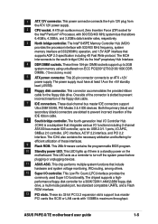
... Port (AGP) RTL8100C PCI1 P4PE-X/TE PCI2 AD1888 SPDIF1 CD1 AUX1 PCI3 PCI4 PCI5 PCI6 01 23 45 Intel I/O Controller Hub (ICH4) ® CR2032 3V Lithium Cell CMOS Power CLRTC ASUS ASIC with Hardware Monitor SB_PWR1 CHASSIS1 2Mbit Firmware Hub Super I/O IDE_LED1 FP_AUDIO1 USB_56 GAME1 PANEL1 30.5cm (12.0in) ASUS P4PE-X/TE motherboard user guide 1-7
... Port (AGP) RTL8100C PCI1 P4PE-X/TE PCI2 AD1888 SPDIF1 CD1 AUX1 PCI3 PCI4 PCI5 PCI6 01 23 45 Intel I/O Controller Hub (ICH4) ® CR2032 3V Lithium Cell CMOS Power CLRTC ASUS ASIC with Hardware Monitor SB_PWR1 CHASSIS1 2Mbit Firmware Hub Super I/O IDE_LED1 FP_AUDIO1 USB_56 GAME1 PANEL1 30.5cm (12.0in) ASUS P4PE-X/TE motherboard user guide 1-7

P4PE-X/TE User Manual
Page 19
... screws! The motherboard uses the ATX form factor that you place it . Failure to the chassis. Make sure to the rear part of the chassis ASUS P4PE-X/TE motherboard user guide 1-9 The edge with external ports goes to unplug the power cord before installing or removing the motherboard. 1.7 Motherboard installation Before you physical...
... screws! The motherboard uses the ATX form factor that you place it . Failure to the chassis. Make sure to the rear part of the chassis ASUS P4PE-X/TE motherboard user guide 1-9 The edge with external ports goes to unplug the power cord before installing or removing the motherboard. 1.7 Motherboard installation Before you physical...

P4PE-X/TE User Manual
Page 21
... CPU is in place, push down the socket lever to 90°-100° angle, otherwise the CPU does not fit in completely. 90 - 100 3. ASUS P4PE-X/TE motherboard user guide 1-11 Socket Lever Make sure that the socket lever is lifted up to a 90°- 100° angle. Position the CPU above...
... CPU is in place, push down the socket lever to 90°-100° angle, otherwise the CPU does not fit in completely. 90 - 100 3. ASUS P4PE-X/TE motherboard user guide 1-11 Socket Lever Make sure that the socket lever is lifted up to a 90°- 100° angle. Position the CPU above...

P4PE-X/TE User Manual
Page 23
...10636.465 1 TS32MLD64V4F3 1 MDOSS6F3G31JB1EAE 1 M368L3223ETM-CCC 1 HYMD232646B8J-D43 AA 1 Obtain DDR DIMMs only from ASUS qualified vendors to both the motherboard and the components. Visit the ASUS website (www.asus.com) for the latest qualified vendors list (QVL). 1.9.2 Installing a DIMM Make sure to install a DIMM... SS SS SS SS SS Component Max. Unlock a DIMM socket by pressing the retaining clips outward. Unlocked Retaining Clip ASUS P4PE-X/TE motherboard user guide 1-13 DDR DIMM notch 2. Failure to do so may cause severe damage to ensure system stability....
...10636.465 1 TS32MLD64V4F3 1 MDOSS6F3G31JB1EAE 1 M368L3223ETM-CCC 1 HYMD232646B8J-D43 AA 1 Obtain DDR DIMMs only from ASUS qualified vendors to both the motherboard and the components. Visit the ASUS website (www.asus.com) for the latest qualified vendors list (QVL). 1.9.2 Installing a DIMM Make sure to install a DIMM... SS SS SS SS SS Component Max. Unlock a DIMM socket by pressing the retaining clips outward. Unlocked Retaining Clip ASUS P4PE-X/TE motherboard user guide 1-13 DDR DIMM notch 2. Failure to do so may cause severe damage to ensure system stability....

P4PE-X/TE User Manual
Page 25
...(RTC) RAM in the BIOS (see section 2.5.1 Power Up Control). Removing the cap will cause system boot failure! ® P4PE-X/TE CLRTC 12 23 P4PE-X/TE Clear RTC RAM Normal (Default) Clear CMOS You do not need to clear the RTC when the system hangs due to default...enter data. You can automatically reset parameter settings to overclocking. Turn OFF the computer and unplug the power cord. 2. 1.11 Jumpers 1. ASUS P4PE-X/TE motherboard user guide 1-15 Keyboard power (3-pin KBPWR1) This jumper allows you press a key on the +5VSB lead, and a corresponding setting in ...
...(RTC) RAM in the BIOS (see section 2.5.1 Power Up Control). Removing the cap will cause system boot failure! ® P4PE-X/TE CLRTC 12 23 P4PE-X/TE Clear RTC RAM Normal (Default) Clear CMOS You do not need to clear the RTC when the system hangs due to default...enter data. You can automatically reset parameter settings to overclocking. Turn OFF the computer and unplug the power cord. 2. 1.11 Jumpers 1. ASUS P4PE-X/TE motherboard user guide 1-15 Keyboard power (3-pin KBPWR1) This jumper allows you press a key on the +5VSB lead, and a corresponding setting in ...
P4PE-X/TE User Manual
Page 27
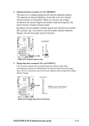
..."Ground" are shorted with intrusion detection feature. PIN 1 P4PE-X/TE Floppy Disk Drive Connector ASUS P4PE-X/TE motherboard user guide 1-17 +5VSB_MB Chassis Signal GND 2. When you wish to record a chassis intrusion event. CHASSIS1 ® P4PE-X/TE (Default) P4PE-X/TE Chassis Alarm Lead 3. Floppy disk drive connector (34-1 ... to this lead to use the chassis intrusion detection feature, remove the jumper cap from the pins. FLOPPY1 ® P4PE-X/TE NOTE: Orient the red markings on the floppy ribbon cable to prevent incorrect insertion when using ribbon cables with pin 5...
..."Ground" are shorted with intrusion detection feature. PIN 1 P4PE-X/TE Floppy Disk Drive Connector ASUS P4PE-X/TE motherboard user guide 1-17 +5VSB_MB Chassis Signal GND 2. When you wish to record a chassis intrusion event. CHASSIS1 ® P4PE-X/TE (Default) P4PE-X/TE Chassis Alarm Lead 3. Floppy disk drive connector (34-1 ... to this lead to use the chassis intrusion detection feature, remove the jumper cap from the pins. FLOPPY1 ® P4PE-X/TE NOTE: Orient the red markings on the floppy ribbon cable to prevent incorrect insertion when using ribbon cables with pin 5...

P4PE-X/TE User Manual
Page 29
...GND +3.3VDC +3.3VDC +12V DC +5.0VDC +5.0VDC GND -5.0VDC GND GND GND PS_ON# GND -12.0VDC +3.3VDC +12V DC GND P4PE-X/TE ATX & Auxiliary Power Connectors 7. Make sure that you to an ATX 12V power supply. Find the proper orientation and push down firmly ...from sound sources such as a CD-ROM, TV tuner, or MPEG card. ® P4PE-X/TE CD1(Black) AUX1 (White) Left Audio Channel Ground Ground Right Audio Channel P4PE-X/TE Internal Audio Connectors ASUS P4PE-X/TE motherboard user guide 1-19 Internal audio connectors (4-pin CD1, AUX1) These connectors allow you connect...
...GND +3.3VDC +3.3VDC +12V DC +5.0VDC +5.0VDC GND -5.0VDC GND GND GND PS_ON# GND -12.0VDC +3.3VDC +12V DC GND P4PE-X/TE ATX & Auxiliary Power Connectors 7. Make sure that you to an ATX 12V power supply. Find the proper orientation and push down firmly ...from sound sources such as a CD-ROM, TV tuner, or MPEG card. ® P4PE-X/TE CD1(Black) AUX1 (White) Left Audio Channel Ground Ground Right Audio Channel P4PE-X/TE Internal Audio Connectors ASUS P4PE-X/TE motherboard user guide 1-19 Internal audio connectors (4-pin CD1, AUX1) These connectors allow you connect...

P4PE-X/TE User Manual
Page 31
... (16-1 pin GAME1) This connector supports a GAME/MIDI module. AGND +5VA BLINE_OUT_R BLINE_OUT_L ® P4PE-X/TE FP_AUDIO1 MIC2 MICPWR Line out_R NC Line out_L P4PE-X/TE Front Panel Audio Connector 11. 10. By default, the pins labeled LINE_OUT_R/BLINE_OUT_R and the pins LINE_OUT_L/BLINE_OUT_L... audio connector (10-1 pin FP_AUDIO1) This is purchased separately. ® P4PE-X/TE P4PE-X/TE Game Connector +5V J1B2 J1CY GND GND J1CX J1B1 +5V GAME1 1 MIDI_IN J2B2 J2CY MIDI_OUT J2CX J2B1 +5V ASUS P4PE-X/TE motherboard user guide 1-21 Connect an optional GAME/MIDI cable to this connector...
... (16-1 pin GAME1) This connector supports a GAME/MIDI module. AGND +5VA BLINE_OUT_R BLINE_OUT_L ® P4PE-X/TE FP_AUDIO1 MIC2 MICPWR Line out_R NC Line out_L P4PE-X/TE Front Panel Audio Connector 11. 10. By default, the pins labeled LINE_OUT_R/BLINE_OUT_R and the pins LINE_OUT_L/BLINE_OUT_L... audio connector (10-1 pin FP_AUDIO1) This is purchased separately. ® P4PE-X/TE P4PE-X/TE Game Connector +5V J1B2 J1CY GND GND J1CX J1B1 +5V GAME1 1 MIDI_IN J2B2 J2CY MIDI_OUT J2CX J2B1 +5V ASUS P4PE-X/TE motherboard user guide 1-21 Connect an optional GAME/MIDI cable to this connector...
P4PE-X/TE User Manual
Page 34
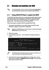
2.1 Managing and updating your screen may not be exactly the same as shown. 4. ASUS EZ Flash V1.00 Copyright (C) 2003, ASUSTeK COMPUTER INC. [Onboard BIOS Information] BIOS Version : ASUS P4PE-X/TE ACPI BIOS Revision 1002 BIOS Model : P4PE-X/TE BIOS Built Date : 10/06/03 Please Enter File Name for NEW BIOS: _... to step 5 without having to type the exact BIOS file name at the EZ Flash screen. 2. Device not ready." if you see ASUS contact information on a piece of booting from A:\, Press [ESC] to reboot The BIOS information in the above screen is accessible by simply pressing...
2.1 Managing and updating your screen may not be exactly the same as shown. 4. ASUS EZ Flash V1.00 Copyright (C) 2003, ASUSTeK COMPUTER INC. [Onboard BIOS Information] BIOS Version : ASUS P4PE-X/TE ACPI BIOS Revision 1002 BIOS Model : P4PE-X/TE BIOS Built Date : 10/06/03 Please Enter File Name for NEW BIOS: _... to step 5 without having to type the exact BIOS file name at the EZ Flash screen. 2. Device not ready." if you see ASUS contact information on a piece of booting from A:\, Press [ESC] to reboot The BIOS information in the above screen is accessible by simply pressing...

P4PE-X/TE User Manual
Page 35
... (Y/N)? _ If you typed Y. When found ." File not found , the following prompts appear if you accidentally typed in File] BIOS Version: P4PE-X/TE Boot Block WARNING! Pressing N exits the EZ Flash screen and reboots the system without updating the BIOS. Press any key to look for NEW ...message, "Press a key to remove the message, then type in the BIOS file name that you downloaded from the ASUS website, then press . Press to reboot" appears. ASUS P4PE-X/TE motherboard user guide 2-3 5. At the prompt, "Please Enter File Name for the file name that you typed. At ...
... (Y/N)? _ If you typed Y. When found ." File not found , the following prompts appear if you accidentally typed in File] BIOS Version: P4PE-X/TE Boot Block WARNING! Pressing N exits the EZ Flash screen and reboots the system without updating the BIOS. Press any key to look for NEW ...message, "Press a key to remove the message, then type in the BIOS file name that you downloaded from the ASUS website, then press . Press to reboot" appears. ASUS P4PE-X/TE motherboard user guide 2-3 5. At the prompt, "Please Enter File Name for the file name that you typed. At ...

P4PE-X/TE User Manual
Page 37
... have problems with the motherboard and you created earlier. 2. At the "A:\" prompt, type AFLASH and then press . 4. ASUS P4PE-X/TE motherboard user guide 2-5 Download an updated ASUS BIOS file from the Internet (WWW or FTP) (see ASUS contact information on page viii for details) and save to the boot floppy disk you are sure that...
... have problems with the motherboard and you created earlier. 2. At the "A:\" prompt, type AFLASH and then press . 4. ASUS P4PE-X/TE motherboard user guide 2-5 Download an updated ASUS BIOS file from the Internet (WWW or FTP) (see ASUS contact information on page viii for details) and save to the boot floppy disk you are sure that...
P4PE-X/TE User Manual
Page 39
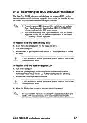
.... 2. See section "2.1.1 Creating a bootable floppy disk." DO NOT shutdown or reset the system while updating the BIOS! To recover the BIOS from the support CD: 1. ASUS P4PE-X/TE motherboard user guide 2-7 To recover the BIOS from a floppy disk: 1. 2.1.3 Recovering the BIOS with CrashFree BIOS 2 The CrashFree BIOS 2 auto recovery tool allows you may... the succeeding screen instructions. The recovered BIOS may not be the latest BIOS version for this disk to download the latest BIOS file. Visit the ASUS website (www.asus.com) to restore the BIOS.
.... 2. See section "2.1.1 Creating a bootable floppy disk." DO NOT shutdown or reset the system while updating the BIOS! To recover the BIOS from the support CD: 1. ASUS P4PE-X/TE motherboard user guide 2-7 To recover the BIOS from a floppy disk: 1. 2.1.3 Recovering the BIOS with CrashFree BIOS 2 The CrashFree BIOS 2 auto recovery tool allows you may... the succeeding screen instructions. The recovered BIOS may not be the latest BIOS version for this disk to download the latest BIOS file. Visit the ASUS website (www.asus.com) to restore the BIOS.
P4PE-X/TE User Manual
Page 41
... menu to configure the default system device used to change the configuration of your BIOS." Use this last option only if the first two failed. ASUS P4PE-X/TE motherboard user guide 2-9 If you are installing a motherboard, reconfiguring your system, or prompted to use the Setup program, you can update using the provided utility...
... menu to configure the default system device used to change the configuration of your BIOS." Use this last option only if the first two failed. ASUS P4PE-X/TE motherboard user guide 2-9 If you are installing a motherboard, reconfiguring your system, or prompted to use the Setup program, you can update using the provided utility...
P4PE-X/TE User Manual
Page 43
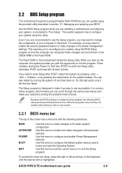
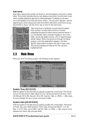
.... While moving around through the various menus and sub-menus. Use the or + keys to familiarize yourself with the legend keys and their corresponding functions. ASUS P4PE-X/TE motherboard user guide 2-11 Valid values for the currently highlighted field. 2.3 Main Menu When you specify (usually the current time). To display a sub-menu, move...
.... While moving around through the various menus and sub-menus. Use the or + keys to familiarize yourself with the legend keys and their corresponding functions. ASUS P4PE-X/TE motherboard user guide 2-11 Valid values for the currently highlighted field. 2.3 Main Menu When you specify (usually the current time). To display a sub-menu, move...
P4PE-X/TE User Manual
Page 45
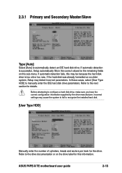
... disk drive, make sure you have the correct configuration information supplied by the drive manufacturer. Refer to manually enter the IDE hard disk drive parameters. ASUS P4PE-X/TE motherboard user guide 2-13 If automatic detection fails, this may be because the hard disk drive is successful, Setup automatically fills in the correct values...
... disk drive, make sure you have the correct configuration information supplied by the drive manufacturer. Refer to manually enter the IDE hard disk drive parameters. ASUS P4PE-X/TE motherboard user guide 2-13 If automatic detection fails, this may be because the hard disk drive is successful, Setup automatically fills in the correct values...

P4PE-X/TE User Manual
Page 47
.... Configuration options: [Disabled] [Enabled] PIO Mode [4] This option lets you set it manually. Set to [Disabled] to [User Type HDD]. Configuration options: [0] [1] [2] [3] [4] [5] [Disabled] 2.3.2 Keyboard Features ASUS P4PE-X/TE motherboard user guide 2-15 Multi-Sector Transfers [Maximum] This option automatically sets the number of sectors per block to [User Type HDD]. You may also...
.... Configuration options: [Disabled] [Enabled] PIO Mode [4] This option lets you set it manually. Set to [Disabled] to [User Type HDD]. Configuration options: [0] [1] [2] [3] [4] [5] [Disabled] 2.3.2 Keyboard Features ASUS P4PE-X/TE motherboard user guide 2-15 Multi-Sector Transfers [Maximum] This option automatically sets the number of sectors per block to [User Type HDD]. You may also...
P4PE-X/TE User Manual
Page 49
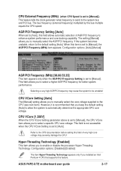
... AGP/PCI Frequency Setting is set to [Manual]) This feature tells the clock generator what frequency to send to the system bus and PCI bus. ASUS P4PE-X/TE motherboard user guide 2-17 CPU External Frequency (MHz) (when CPU Speed is set to [Manual]. The bus frequency (external frequency) multiplied by the bus multiple...
... AGP/PCI Frequency Setting is set to [Manual]) This feature tells the clock generator what frequency to send to the system bus and PCI bus. ASUS P4PE-X/TE motherboard user guide 2-17 CPU External Frequency (MHz) (when CPU Speed is set to [Manual]. The bus frequency (external frequency) multiplied by the bus multiple...


