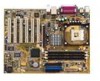
Asus P4pex-te - P4PE X TE
Asus P4pex-te
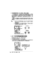
Related Manual Pages


Similar Questions

How Can I Boot P4pe-x/te Motherboard From Usb Flash Memory?
is there any Bios update or any other way to boot P4pe-X TE motherboard From a usb Flash memory?P4PE...
is there any Bios update or any other way to boot P4pe-X TE motherboard From a usb Flash memory?P4PE...
(Posted by Barfess 5 years ago)