Motherboard DIY Troubleshooting Guide
Page 2
...modified or altered, unless such repair, modification of the product is authorized in any form or by any means, except documentation kept by ASUS; SPECIFICATIONS AND INFORMATION CONTAINED IN THIS MANUAL ARE FURNISHED FOR INFORMATIONAL USE ONLY, AND ARE SUBJECT TO CHANGE AT ANY TIME WITHOUT NOTICE, AND... SHOULD NOT BE CONSTRUED AS A COMMITMENT BY ASUS. ASUS ASSUMES NO RESPONSIBILITY OR LIABILITY FOR ANY ERRORS OR INACCURACIES THAT MAY APPEAR IN THIS MANUAL, INCLUDING THE PRODUCTS AND SOFTWARE DESCRIBED IN ...
...modified or altered, unless such repair, modification of the product is authorized in any form or by any means, except documentation kept by ASUS; SPECIFICATIONS AND INFORMATION CONTAINED IN THIS MANUAL ARE FURNISHED FOR INFORMATIONAL USE ONLY, AND ARE SUBJECT TO CHANGE AT ANY TIME WITHOUT NOTICE, AND... SHOULD NOT BE CONSTRUED AS A COMMITMENT BY ASUS. ASUS ASSUMES NO RESPONSIBILITY OR LIABILITY FOR ANY ERRORS OR INACCURACIES THAT MAY APPEAR IN THIS MANUAL, INCLUDING THE PRODUCTS AND SOFTWARE DESCRIBED IN ...

Motherboard DIY Troubleshooting Guide
Page 3
Features Contents Notices v Safety information vi About this guide vii ASUS contact information viii P4PE BP specifications summary ix Chapter 1: Product introduction 1.1 Welcome 1-2 1.2 Package contents 1-2 1.3 Special features 1-3 1.4 Motherboard components 1-4 1.5 Motherboard layout 1-8 1.6...for this motherboard 1-15 1.11 Jumpers 1-16 1.12 Connectors 1-18 Chapter 2: BIOS information 2.1 Managing and updating your BIOS 2-2 2.1.1 Using ASUS EZ Flash to update the BIOS 2-2 2.1.2 Using AFLASH to update the BIOS 2-4 2.1.3 CrashFree BIOS 2 feature 2-7 2.2 BIOS Setup program 2-8 ...
Features Contents Notices v Safety information vi About this guide vii ASUS contact information viii P4PE BP specifications summary ix Chapter 1: Product introduction 1.1 Welcome 1-2 1.2 Package contents 1-2 1.3 Special features 1-3 1.4 Motherboard components 1-4 1.5 Motherboard layout 1-8 1.6...for this motherboard 1-15 1.11 Jumpers 1-16 1.12 Connectors 1-18 Chapter 2: BIOS information 2.1 Managing and updating your BIOS 2-2 2.1.1 Using ASUS EZ Flash to update the BIOS 2-2 2.1.2 Using AFLASH to update the BIOS 2-4 2.1.3 CrashFree BIOS 2 feature 2-7 2.2 BIOS Setup program 2-8 ...

Motherboard DIY Troubleshooting Guide
Page 9
P4PE BP specifications summary CPU Chipset Front Side Bus (FSB) Memory Expansion slots IDE Audio (optional) LAN (optional) Special features Rear panel I/O Socket 478 for Intel® Pentium&#... PCI slot) 2 x UltraDMA 100/66/33 connectors ADI AD1980 6-channel audio CODEC BROADCOM® BCM4401 Fast Ethernet controller ASUS JumperFree™ mode ASUS EZ Plug™ ASUS MyLogo2 ASUS Q-Fan ASUS EZ Flash ASUS Instant Music ASUS POST Reporter Power Loss Restart SFS (Stepless Frequency Selection) Adjustable CPU VCORE, memory, and AGP voltages Multi-language BIOS 1 x Parallel...
P4PE BP specifications summary CPU Chipset Front Side Bus (FSB) Memory Expansion slots IDE Audio (optional) LAN (optional) Special features Rear panel I/O Socket 478 for Intel® Pentium&#... PCI slot) 2 x UltraDMA 100/66/33 connectors ADI AD1980 6-channel audio CODEC BROADCOM® BCM4401 Fast Ethernet controller ASUS JumperFree™ mode ASUS EZ Plug™ ASUS MyLogo2 ASUS Q-Fan ASUS EZ Flash ASUS Instant Music ASUS POST Reporter Power Loss Restart SFS (Stepless Frequency Selection) Adjustable CPU VCORE, memory, and AGP voltages Multi-language BIOS 1 x Parallel...

Motherboard DIY Troubleshooting Guide
Page 10
P4PE BP specifications summary Internal I/O BIOS features Industry standard Manageability Form Factor Support CD contents 1 x USB 2.0/1.1 connector for 2 additional USB ports CPU/Power/Chassis fan connectors 20-pin/4-....3, CrashFree BIOS, Multi-language BIOS, ASUS EZ Flash, ASUS MyLogo2, ASUS Instant Music PCI 2.2, USB 2.0 WfM 2.0. x DMI 2.0, WOL/WOR by PME, chassis intrusion, SMBus ATX form factor: 12 in x 9.0 in (30.5 cm x 22.9 cm) Device drivers ASUS PC Probe ASUS LiveUpdate Trend Micro™ PC-cillin 2002 anti-virus software * Specifications are subject to change without...
P4PE BP specifications summary Internal I/O BIOS features Industry standard Manageability Form Factor Support CD contents 1 x USB 2.0/1.1 connector for 2 additional USB ports CPU/Power/Chassis fan connectors 20-pin/4-....3, CrashFree BIOS, Multi-language BIOS, ASUS EZ Flash, ASUS MyLogo2, ASUS Instant Music PCI 2.2, USB 2.0 WfM 2.0. x DMI 2.0, WOL/WOR by PME, chassis intrusion, SMBus ATX form factor: 12 in x 9.0 in (30.5 cm x 22.9 cm) Device drivers ASUS PC Probe ASUS LiveUpdate Trend Micro™ PC-cillin 2002 anti-virus software * Specifications are subject to change without...

Motherboard DIY Troubleshooting Guide
Page 14
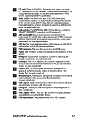
Refer to facilitate the installation and future upgrades. DDR DIMM sockets 5. IDE connectors 9. South Bridge controller 10. ASUS ASIC 14. Line Out jack (optional) 25. USB 2.0 ports 1 and 2 27. Serial ports 28....Speech controller 11. LAN controller (optional) 18 AGP warning LED 19. RJ-45 port (optional) 23. Flash ROM 12. ASUS EZ Plug™ 12V connector 6. Audio CODEC (optional) 17. Microphone jack (optional) 26. 1.4 Motherboard components Before you ... on the components. 1-4 Chapter 1: Product introduction Refer to Chapter 2 for the specifications of each component.
Refer to facilitate the installation and future upgrades. DDR DIMM sockets 5. IDE connectors 9. South Bridge controller 10. ASUS ASIC 14. Line Out jack (optional) 25. USB 2.0 ports 1 and 2 27. Serial ports 28....Speech controller 11. LAN controller (optional) 18 AGP warning LED 19. RJ-45 port (optional) 23. Flash ROM 12. ASUS EZ Plug™ 12V connector 6. Audio CODEC (optional) 17. Microphone jack (optional) 26. 1.4 Motherboard components Before you ... on the components. 1-4 Chapter 1: Product introduction Refer to Chapter 2 for the specifications of each component.
Motherboard DIY Troubleshooting Guide
Page 16
... connector. The Intel® 845PE Memory Controller Hub (MCH) provides the processor interface with 533/400 MHz system bus that supports AGP 2.0 specification including 4X Fast Write protocol. The MCH interconnects to an ATX +12V power supply. This 4Mb firmware contains the programmable BIOS program. 12 ... a standard power supply to this connector to provide sufficient power to 2GB system memory using unbuffered non-ECC PC2700/2100/1600 DDR DIMMs. 5 ASUS EZ Plug™ +12V connector. Connect a 4pin device connector from the ATX 12V power supply. 2 CPU socket. The ICH4 also contains...
... connector. The Intel® 845PE Memory Controller Hub (MCH) provides the processor interface with 533/400 MHz system bus that supports AGP 2.0 specification including 4X Fast Write protocol. The MCH interconnects to an ATX +12V power supply. This 4Mb firmware contains the programmable BIOS program. 12 ... a standard power supply to this connector to provide sufficient power to 2GB system memory using unbuffered non-ECC PC2700/2100/1600 DDR DIMMs. 5 ASUS EZ Plug™ +12V connector. Connect a 4pin device connector from the ATX 12V power supply. 2 CPU socket. The ICH4 also contains...
Motherboard DIY Troubleshooting Guide
Page 17
... slot) supports future ASUS function cards compliant to a Local Area Network (LAN) through a network hub. (on audio models only) 17 LAN controller. Serving as a smart burn-out protection for connecting USB 2.0 devices. 27 Serial ports. This port allows connection to PCI specification. 16 Audio CODEC.... These two 4-pin Universal Serial Bus (USB) ports are for 10BASE-T/100BASE-TX networking. (on LAN models only) 18 AGP warning LED. ASUS P4PE BP motherboard user guide 1-7 These six 32-bit PCI 2.2 expansion slots support bus master PCI cards like SCSI or LAN cards with 133MB/s maximum ...
... slot) supports future ASUS function cards compliant to a Local Area Network (LAN) through a network hub. (on audio models only) 17 LAN controller. Serving as a smart burn-out protection for connecting USB 2.0 devices. 27 Serial ports. This port allows connection to PCI specification. 16 Audio CODEC.... These two 4-pin Universal Serial Bus (USB) ports are for 10BASE-T/100BASE-TX networking. (on LAN models only) 18 AGP warning LED. ASUS P4PE BP motherboard user guide 1-7 These six 32-bit PCI 2.2 expansion slots support bus master PCI cards like SCSI or LAN cards with 133MB/s maximum ...
Motherboard DIY Troubleshooting Guide
Page 21
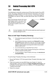
...visit www.intel.com/ info/hyperthreading. It is set to ensure system stability and performance. 3. Buy an Intel Pentium 4 CPU that should match a specific corner of the CPU socket. Reboot the computer. Note in the 478-pin package with 512KB L2 cache on 0.13 micron process. Under Linux, use... front side bus (FSB), and allows data transfer rates of the CPU into the socket may bend the pins and severely damage the CPU! ASUS P4PE BP motherboard user guide 1-11 Power up the system and enter BIOS Setup (see Chapter 2). This mark indicates the processor Pin 1 that supports Hyper...
...visit www.intel.com/ info/hyperthreading. It is set to ensure system stability and performance. 3. Buy an Intel Pentium 4 CPU that should match a specific corner of the CPU socket. Reboot the computer. Note in the 478-pin package with 512KB L2 cache on 0.13 micron process. Under Linux, use... front side bus (FSB), and allows data transfer rates of the CPU into the socket may bend the pins and severely damage the CPU! ASUS P4PE BP motherboard user guide 1-11 Power up the system and enter BIOS Setup (see Chapter 2). This mark indicates the processor Pin 1 that supports Hyper...

Motherboard DIY Troubleshooting Guide
Page 29
... connector and another UltraDMA/100/66 cable. BIOS supports specific device bootup. one for the secondary IDE connector. 1. The hole near the blue connector on the UltraDMA/100/66 cable is intentional. ® P4PE BP NOTE: Orient the red markings (usually zigzag) on ... PRI_IDE, SEC_IDE) This connector supports the provided UltraDMA/100/66 IDE hard disk ribbon cable. SEC_IDE PRI_IDE P4PE BP IDE Connectors PIN 1 PIN 1 10. It is removed to this connector. ® P4PE BP TRPWR1 Ground TRPWR P4PE BP Power Supply Thermal Connector ASUS P4PE BP motherboard user guide 1-19 3.
... connector and another UltraDMA/100/66 cable. BIOS supports specific device bootup. one for the secondary IDE connector. 1. The hole near the blue connector on the UltraDMA/100/66 cable is intentional. ® P4PE BP NOTE: Orient the red markings (usually zigzag) on ... PRI_IDE, SEC_IDE) This connector supports the provided UltraDMA/100/66 IDE hard disk ribbon cable. SEC_IDE PRI_IDE P4PE BP IDE Connectors PIN 1 PIN 1 10. It is removed to this connector. ® P4PE BP TRPWR1 Ground TRPWR P4PE BP Power Supply Thermal Connector ASUS P4PE BP motherboard user guide 1-19 3.
Motherboard DIY Troubleshooting Guide
Page 33
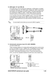
...P4PE BP Internal Audio Connectors ASUS P4PE BP motherboard user guide 1-23 USB header (10-1 pin USB_56) If the USB ports on audio models only) These connectors allow you can use the USB 2.0 capability. If your package came with a USB 2.0/GAME module, connect the USB cable to interface with a voice modem card with USB 2.0 specification... that support the next generation USB peripherals such as a CD-ROM, TV tuner, or MPEG card. USB+5V LP5LP5+ GND NC ® P4PE BP P4PE BP USB 2.0 Header USB_56 1 USB+5V LP4LP4+ GND 11...
...P4PE BP Internal Audio Connectors ASUS P4PE BP motherboard user guide 1-23 USB header (10-1 pin USB_56) If the USB ports on audio models only) These connectors allow you can use the USB 2.0 capability. If your package came with a USB 2.0/GAME module, connect the USB cable to interface with a voice modem card with USB 2.0 specification... that support the next generation USB peripherals such as a CD-ROM, TV tuner, or MPEG card. USB+5V LP5LP5+ GND NC ® P4PE BP P4PE BP USB 2.0 Header USB_56 1 USB+5V LP4LP4+ GND 11...

Motherboard DIY Troubleshooting Guide
Page 45
.... ASUS P4PE BP motherboard user guide 2-9 To exit the help document. Navigation Key(s) or Left or Right arrow Up or Down arrow - (minus key) + (plus key) or spacebar or or Function Description Displays the General Help screen from anywhere in the BIOS Setup Jumps to the Exit menu or returns to the Item Specific...
.... ASUS P4PE BP motherboard user guide 2-9 To exit the help document. Navigation Key(s) or Left or Right arrow Up or Down arrow - (minus key) + (plus key) or spacebar or or Function Description Displays the General Help screen from anywhere in the BIOS Setup Jumps to the Exit menu or returns to the Item Specific...

Motherboard DIY Troubleshooting Guide
Page 46
... sub-menus. This pointer indicates that you specify (usually the current date). Practice navigating through the Setup program, note that explanations appear in the Item Specific Help window located to the main menu. System Date [XX/XX/XXXX] Sets the system to the date that you can display a sub-menu from...
... sub-menus. This pointer indicates that you specify (usually the current date). Practice navigating through the Setup program, note that explanations appear in the Item Specific Help window located to the main menu. System Date [XX/XX/XXXX] Sets the system to the date that you can display a sub-menu from...

Motherboard DIY Troubleshooting Guide
Page 52
... Chapter 2: BIOS information Memory Frequency [Auto] This field determines whether the memory clock frequency is set to [Auto]. The setting [Manual] allows you to select a specific CPU core voltage. DDR Reference Voltage [Auto] This item controls the DDR SDRAM operating voltage. Configuration options: [Auto] [Manual] AGP/PCI Frequency (MHz) [66.66...
... Chapter 2: BIOS information Memory Frequency [Auto] This field determines whether the memory clock frequency is set to [Auto]. The setting [Manual] allows you to select a specific CPU core voltage. DDR Reference Voltage [Auto] This item controls the DDR SDRAM operating voltage. Configuration options: [Auto] [Manual] AGP/PCI Frequency (MHz) [66.66...

Motherboard DIY Troubleshooting Guide
Page 62
.... Thus, connection cannot be made on the +5VSB lead. Power Up On PCI Device [Disabled] When set to [Enabled], this parameter allows you to use specific keys on the keyboard to turn on . Configuration options: [Disabled] [Enabled] 2-26 Chapter 2: BIOS information Turning an external modem off and then back on while...
.... Thus, connection cannot be made on the +5VSB lead. Power Up On PCI Device [Disabled] When set to [Enabled], this parameter allows you to use specific keys on the keyboard to turn on . Configuration options: [Disabled] [Enabled] 2-26 Chapter 2: BIOS information Turning an external modem off and then back on while...

Motherboard DIY Troubleshooting Guide
Page 64
...". This item appears only when the Q-Fan Control item is the minimum fan speed ratio. The default [10/15] is set to the motherboard, the specific field shows N/A.
...". This item appears only when the Q-Fan Control item is the minimum fan speed ratio. The default [10/15] is set to the motherboard, the specific field shows N/A.
