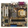
Motherboard DIY Troubleshooting Guide
Page 12
... missing, contact your retailer. 1-2 Chapter 1: Product introduction The motherboard delivers a host of ASUS quality motherboards! Supporting up to set a new benchmark for buying the ASUS® P4GE-MX motherboard! 1.1 Welcome! Thank you ahead in your motherboard package for the following items. ASUS P4GE-MX motherboard ASUS motherboard support CD 1 x IDE cable 1 x Floppy disk cable I/O shield Bag of extra...
Motherboard DIY Troubleshooting Guide
Page 13
... 512/256KB L2 cache on USB 2.0 - Integrated Graphics The Intel® 845GE chipset delivers realistic 3D/2D graphics with digital connectivity to powerful speaker systems. ASUS P4GE-MX motherboard 1-3 USB 2.0 is backward compatible with USB 1.1. 6-Channel Audio solution Onboard is the Realtek® ALC655 AC'97 CODEC. supporting up to buy advanced sound...
Motherboard DIY Troubleshooting Guide
Page 15
... chassis. 3. Onboard LED The motherboard comes with the component. 5. The illustration below shows the location of the onboard LED. ® P4GE-MX P4GE-MX Onboard LED SB_PWR ON Standby Power OFF Powered Off ASUS P4GE-MX motherboard 1-5 1.4 Before you proceed Take note of the following precautions before removing or plugging in any motherboard component. Failure to do...
Motherboard DIY Troubleshooting Guide
Page 17
Doing so may damage the motherboard. Place this side towards the rear of the chassis as indicated in the image below. 1.5.3 Screw holes Place six (6) screws into the chassis in the correct orientation. 1.5.2 Placement direction When installing the motherboard, make sure that you place it into the holes indicated by circles to secure the motherboard to the rear part of the chassis ASUS P4GE-MX motherboard 1-7 Do not overtighten the screws! The edge with external ports goes to the chassis.
Motherboard DIY Troubleshooting Guide
Page 19
... on the motherboard. 2. otherwise, the CPU does not fit in one correct orientation. 1.6.2 Installing the CPU Follow these steps to indicate that it is locked. ASUS P4GE-MX motherboard 1-9
Motherboard DIY Troubleshooting Guide
Page 21
... PCI cards on the system and change the necessary BIOS settings, if any. See Chapter 2 for the expansion card according to the card. used - - - - - shared - - - - - - ASUS P4GE-MX motherboard 1-11 used - - - - PCI slot 3 shared Onboard USB 1.1 controller 1shared Onboard USB 1.1 controller 2 - - - Onboard Audio - shared - - - - - - used - - Install the drivers and/or software applications for...
Motherboard DIY Troubleshooting Guide
Page 23
To erase the RTC RAM: 1. Keep the cap on the jumper default position. ASUS P4GE-MX motherboard 1-13 1.9 Jumpers 1. The RAM data in CMOS. Turn OFF the computer and unplug the power cord. 2. Move the jumper cap from pins 2-3 (default) to ... system setup information such as system passwords, is powered by erasing the CMOS RTC RAM data. Removing the cap will cause system boot failure! ® P4GE-MX P4GE-MX Clear RTC RAM CLRTC 12 23 Clear CMOS Normal (Default) You do not need to clear the RTC when the system hangs due to pins...
Motherboard DIY Troubleshooting Guide
Page 25
... In Line Out Mic In 4-Speaker Line In Front Speaker Out Rear Speaker Out 6-Speaker Bass/Center Front Speaker Out Rear Speaker Out 7. VGA port. ASUS P4GE-MX motherboard 1-15 This port connects to your serial mouse and other serial devices. 11. RJ-45 port. Line Out jack. PS/2 mouse port.
Motherboard DIY Troubleshooting Guide
Page 27
Left Audio Channel Ground Ground Right Audio Channel Left Audio Channel Ground Ground Right Audio Channel ® P4GE-MX CD(Black) AUX(White) P4GE-MX Internal audio connectors ASUS P4GE-MX motherboard 1-17 ATX power connectors (20-pin ATX_POWER1, 4-pin ATX12V1) These connectors connect to fit these... recommended wattage is inadequate. 4. 3. ATX_POWER1 Pin 1 +12.0VDC +5VSB ATX12V1 PWR_OK COM ® P4GE-MX +12V DC GND +12V DC GND +5.0VDC COM +5.0VDC COM +3.3VDC P4GE-MX ATX power connectors +3.3VDC +5.0VDC +5.0VDC -5.0VDC COM COM COM PS_ON# COM -12.0VDC +3.3VDC Make...
Motherboard DIY Troubleshooting Guide
Page 29
AGND +5VA BLINE_OUT_R BLINE_OUT_L ® P4GE-MX FP_AUDIO MIC2 MICPWR Line out_R NC Line out_L P4GE-MX Front panel audio connector 8. CHASSIS +5VSB_MB Chassis Signal GND ® P4GE-MX (Default) P4GE-MX Chassis intrusion connector ASUS P4GE-MX motherboard 1-19 When you wish to record a chassis intrusion event. If you remove any chassis component, the sensor triggers and sends a high-level signal...
Motherboard DIY Troubleshooting Guide
Page 31
PLED1 1 ASUS P4GE-MX motherboard 1-21 Connect the COM2 cable to a COM2 bracket. Serial connector (9-pin COM2 ) This 9-pin connector connects to this connector and install the bracket on the system power. ® P4GE-MX P4GE-MX PLED setting PLED+ NC PLED- Power LED connector (3-pin PLED1 ) This 3-pin connector connects to a 3-pin system power LED. The LED lights up when you turn on an available slot in the rear panel of the chassis. ® P4GE-MX PIN 1 COM2 P4GE-MX Serial port connector The COM2 bracket is purchased separately. 12. 11.
Motherboard DIY Troubleshooting Guide
Page 33
Detailed descriptions of the BIOS parameters are also provided. Chapter 2 This chapter tells how to change system settings through the BIOS Setup menus. BIOS information ASUS P4GE-MX motherboard 2-1
Motherboard DIY Troubleshooting Guide
Page 35
...the bootable floppy disk you created earlier. 2. Insert a 1.44 MB floppy disk into the floppy drive. 3. d. Click File from the ASUS website (www.asus.com). Windows® XP environment a. Insert the disk that contains the new BIOS file into the floppy disk drive. Reboot the computer....with the executable Flash Memory Writer Utility (AWDFLASH.EXE). Rename the file to *.BIN and save it to display the following screen. 5. ASUS P4GE-MX motherboard 2-3 From your Windows desktop, click on Start, then select My Computer. Download the latest BIOS file from the menu, then select ...
Motherboard DIY Troubleshooting Guide
Page 37
... To recover the BIOS from the support CD: 1. Boot the system. 2. Checking for floppy... Checking for floppy... Reading file "P4GE-MX.ROM". Starting BIOS recovery... If there is detected, the following screen message appears. Floppy not found in the CD-ROM. When...no floppy disk found ! Starting BIOS recovery... CD-ROM found ! Start flashing... The support CD contains the a working BIOS for this motherboard. ASUS P4GE-MX motherboard 2-5 DO NOT shut down or reset the system while updating the BIOS! DO NOT shut down or reset the system while updating the ...
Motherboard DIY Troubleshooting Guide
Page 39
If you selected the option to update the BIOS from a file, a window pops up prompting you wish to locate the file. From the FTP site, select the BIOS version that you to download. 2. Select the file, click Save, then follow the screen instructions to complete the update process. Click Next. 5. ASUS P4GE-MX motherboard 2-7 Follow the instructions on the succeeding screens to complete the update process.
Motherboard DIY Troubleshooting Guide
Page 41
ASUS P4GE-MX motherboard 2-9 2.2.1 BIOS menu screen Menu items Menu bar Field settings General help Sub-menu items Legend bar 2.2.2 Menu bar The menu bar on top of ... setup screens shown in this chapter are for reference purposes only, and may not exactly match what you see on your screen. • Visit the ASUS website (www.asus.com) to download the latest BIOS information.
Motherboard DIY Troubleshooting Guide
Page 43
...: (00 to 2099). System Date [mm/dd/yy] Sets the system to navigate through them. The format is month, day, year. Configuration options: [Setup] [System] ASUS P4GE-MX motherboard 2-11
Motherboard DIY Troubleshooting Guide
Page 45
... for this may be because the hard disk drive is successful, the setup BIOS automatically fills in the value from the drive documentation then press . ASUS P4GE-MX motherboard 2-13 If automatic detection fails, this item if you obtained from the drive documentation, then press . Configuration options: [CHS] [LBA] [Large] [Auto] Manual HDD...
Motherboard DIY Troubleshooting Guide
Page 47
Configuration options: [Manual] [By SPD] CAS Latency Time [1.5] Sets the latency between the DRAM command and the time the data actually become available. Configuration options: [7] [6] [5] ASUS P4GE-MX motherboard 2-15 Set to manual if you want to Precharge Delay [7] Controls the number of DRAM clocks used for the DRAM parameters. 2.4 Advanced menu 2.4.1 Advanced Chipset Features DRAM Timing Selectable [By SPD] Sets the DRAM Timing configuration. Configuration options: [1.5] [2] [2.5] [3] Active to configure each item on your own.
Motherboard DIY Troubleshooting Guide
Page 49
Set this item to limit the CPUID maximum value. Configuration options: [Auto] [Mode 0] [Mode 1] [Mode 2] [Mode 3] [Mode 4] ASUS P4GE-MX motherboard 2-17 Configuration options: [Disabled] [Enabled] On-Chip Primary PCI IDE [Enabled] Disables or enables the On-chip Primary PCI IDE support. Configuration options: [Disabled] [+/- 0....