
P2Z-VM User Manual
Page 1
R P2Z-VM Pentium® III / II / CeleronTM Motherboard USER'S MANUAL
R P2Z-VM Pentium® III / II / CeleronTM Motherboard USER'S MANUAL

P2Z-VM User Manual
Page 4
...Recommended Heatsinks for ISA Cards 26 Accelerated Graphics Port 26 5. HARDWARE SETUP 12 Layout of Chipset Features Setup 48 4 ASUS P2Z-VM User's Manual Motherboard Settings 14 Jumpers 14 2. System Memory (DIMM 19 DIMM Memory Installation Procedures 20 3. BIOS SETUP 38 Flash Memory ...Standard CMOS Setup 42 BIOS Features Setup 45 Details of BIOS Features Setup 45 Chipset Features Setup 48 Details of the ASUS P2Z-VM Motherboard 12 Hardware Setup Steps 14 1. Expansion Cards 25 Expansion Card Installation Procedure 25 Assigning IRQs for Expansion Cards 25 Assigning...
...Recommended Heatsinks for ISA Cards 26 Accelerated Graphics Port 26 5. HARDWARE SETUP 12 Layout of Chipset Features Setup 48 4 ASUS P2Z-VM User's Manual Motherboard Settings 14 Jumpers 14 2. System Memory (DIMM 19 DIMM Memory Installation Procedures 20 3. BIOS SETUP 38 Flash Memory ...Standard CMOS Setup 42 BIOS Features Setup 45 Details of BIOS Features Setup 45 Chipset Features Setup 48 Details of the ASUS P2Z-VM Motherboard 12 Hardware Setup Steps 14 1. Expansion Cards 25 Expansion Card Installation Procedure 25 Assigning IRQs for Expansion Cards 25 Assigning...
P2Z-VM User Manual
Page 7
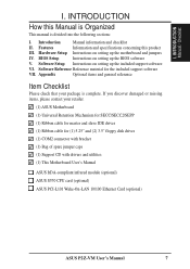
... spare jumper caps (1) Support CD with drivers and utilities (1) This Motherboard User's Manual ASUS IrDA-compliant infrared module (optional) ASUS S370 CPU card (optional) ASUS PCI-L101 Wake-On-LAN 10/100 Ethernet Card (optional) ASUS P2Z-VM User's Manual 7 I . Software Setup Instructions on setting up the motherboard and jumpers IV. Appendix Optional items and general reference Item...
... spare jumper caps (1) Support CD with drivers and utilities (1) This Motherboard User's Manual ASUS IrDA-compliant infrared module (optional) ASUS S370 CPU card (optional) ASUS PCI-L101 Wake-On-LAN 10/100 Ethernet Card (optional) ASUS P2Z-VM User's Manual 7 I . Software Setup Instructions on setting up the motherboard and jumpers IV. Appendix Optional items and general reference Item...

P2Z-VM User Manual
Page 8
... Accelerated Graphics Port card for the demanding PC user who wants advanced features processed by the fastest CPU. FEATURES Specifications II. FEATURES Features of the ASUS P2Z-VM Motherboard The ASUS P2Z-VM is used to physically transport commands and information between SMBus devices. • PCI & ISA Expansion Slots: Provides three 32-bit PCI slots and one... two high-speed UART compatible serial ports and one parallel port with two connectors that support four IDE devices in a Single Edge Processor Package (SEPP). 8 ASUS P2Z-VM User's Manual
... Accelerated Graphics Port card for the demanding PC user who wants advanced features processed by the fastest CPU. FEATURES Specifications II. FEATURES Features of the ASUS P2Z-VM Motherboard The ASUS P2Z-VM is used to physically transport commands and information between SMBus devices. • PCI & ISA Expansion Slots: Provides three 32-bit PCI slots and one... two high-speed UART compatible serial ports and one parallel port with two connectors that support four IDE devices in a Single Edge Processor Package (SEPP). 8 ASUS P2Z-VM User's Manual

P2Z-VM User Manual
Page 9
...Optimized Performance: Supports the new generation memory - Performance Features: • Concurrent PCI: Concurrent PCI allows multiple PCI transfers from PCI mas- ASUS P2Z-VM User's Manual 9 The new PC'98 requirements for systems and components are based on the following high-level goals: Support for Plug and ...is no need to the memory and processor. • Double the IDE Transfer Speed: This motherboard with existing ATA-2 IDE specs so there is that supports autodetection of motherboards meet PC'98 compliancy. II. The best of all system components, and 32-bit device ...
...Optimized Performance: Supports the new generation memory - Performance Features: • Concurrent PCI: Concurrent PCI allows multiple PCI transfers from PCI mas- ASUS P2Z-VM User's Manual 9 The new PC'98 requirements for systems and components are based on the following high-level goals: Support for Plug and ...is no need to the memory and processor. • Double the IDE Transfer Speed: This motherboard with existing ATA-2 IDE specs so there is that supports autodetection of motherboards meet PC'98 compliancy. II. The best of all system components, and 32-bit device ...

P2Z-VM User Manual
Page 12
ATI Multimedia Connector III. HARDWARE SETUP Layout of the ASUS P2Z-VM Motherboard DIMM Socket 1 (64/72 bit, 168 pin module) DIMM Socket 2 (...CD_IN 32-bit PCI Audio Chipset Accelerated Graphics Port SB-LINK COM2 Multi-I/O & Keyboard Controller PCI Slot 1 (PCI1) P2Z-VM PCI Slot 2 (PCI2) AUDIO_EN PCI Slot 3 (PCI3) Intel PIIX4E PCIset ISA Slot 1 (ISA1) R ATI...) FREQ MULT ASUS ASIC BF0 BF1 BF2 BF3 WOL_CON IR 2Mbit Flash EEPROM (Programable BIOS) (Grayed items are optional at the time of purchase.) Panel Connectors 12 ASUS P2Z-VM User's Manual H/W SETUP Motherboard Layout III.
ATI Multimedia Connector III. HARDWARE SETUP Layout of the ASUS P2Z-VM Motherboard DIMM Socket 1 (64/72 bit, 168 pin module) DIMM Socket 2 (...CD_IN 32-bit PCI Audio Chipset Accelerated Graphics Port SB-LINK COM2 Multi-I/O & Keyboard Controller PCI Slot 1 (PCI1) P2Z-VM PCI Slot 2 (PCI2) AUDIO_EN PCI Slot 3 (PCI3) Intel PIIX4E PCIset ISA Slot 1 (ISA1) R ATI...) FREQ MULT ASUS ASIC BF0 BF1 BF2 BF3 WOL_CON IR 2Mbit Flash EEPROM (Programable BIOS) (Grayed items are optional at the time of purchase.) Panel Connectors 12 ASUS P2Z-VM User's Manual H/W SETUP Motherboard Layout III.

P2Z-VM User Manual
Page 14
... you do not have one, touch both of switches and/or jumpers. H/W SETUP Motherboard Settings P2Z-VM P2Z-VM VGA Interrupt Setting R INT_EN 123 123 Disable Enable (Default) Setting INT EN Disable [1-2] (default) Enable [2-3] 14 ASUS P2Z-VM User's Manual Install Expansion Cards 5. WARNING! Computer motherboards and expansion cards contain very delicate Integrated Circuit (IC) chips. Unplug your computer...
... you do not have one, touch both of switches and/or jumpers. H/W SETUP Motherboard Settings P2Z-VM P2Z-VM VGA Interrupt Setting R INT_EN 123 123 Disable Enable (Default) Setting INT EN Disable [1-2] (default) Enable [2-3] 14 ASUS P2Z-VM User's Manual Install Expansion Cards 5. WARNING! Computer motherboards and expansion cards contain very delicate Integrated Circuit (IC) chips. Unplug your computer...

P2Z-VM User Manual
Page 15
.... WARNING! H/W SETUP Motherboard Settings III. Setting Enable Disable VGAEN [1-2] (default) [2-3] VGAEN 123 123 R P2Z-VM Enable Disable (Default) P2Z-VM VGA Setting 3. Setting Disable Enable KB WAK [1-2] (default) [2-3] KB_WAK 123 123 Disable Enable (Default) R P2Z-VM P2Z-VM Keyboard Power (Wake) Up ASUS P2Z-VM User's Manual 15 HARDWARE...KB_WAK) This allows you wish to use your keyboard (by pressing any key or the spacebar, depending on your motherboard) to Disable because not all computers have the appropriate ATX power supply. The default is set this jumper to...
.... WARNING! H/W SETUP Motherboard Settings III. Setting Enable Disable VGAEN [1-2] (default) [2-3] VGAEN 123 123 R P2Z-VM Enable Disable (Default) P2Z-VM VGA Setting 3. Setting Disable Enable KB WAK [1-2] (default) [2-3] KB_WAK 123 123 Disable Enable (Default) R P2Z-VM P2Z-VM Keyboard Power (Wake) Up ASUS P2Z-VM User's Manual 15 HARDWARE...KB_WAK) This allows you wish to use your keyboard (by pressing any key or the spacebar, depending on your motherboard) to Disable because not all computers have the appropriate ATX power supply. The default is set this jumper to...

P2Z-VM User Manual
Page 16
... using this jumper. The BUS Clock multiplied by the BUS Ratio equals the CPU's Internal frequency (the advertised CPU speed). H/W SETUP Motherboard Settings III. R R P2Z-VM AUDIO_EN 123 123 Enable Disable (Default) P2Z-VM Audio Setting 5. CPU Bus Frequency Selection (FS0, FS1, FS2, FS3, FS4) This option tells the clock generator what frequency to ...123 FS0 FS1 FS2 FS3 FS4 CPU 124.0MHz 124.0MHz 133.0MHz 133.0MHz PCI 41.3MHz 31.0MHz 44.3MHz 33.3MHz 16 ASUS P2Z-VM User's Manual HARDWARE SETUP 4. This allows the selection of the CPU's External frequency (or BUS Clock).
... using this jumper. The BUS Clock multiplied by the BUS Ratio equals the CPU's Internal frequency (the advertised CPU speed). H/W SETUP Motherboard Settings III. R R P2Z-VM AUDIO_EN 123 123 Enable Disable (Default) P2Z-VM Audio Setting 5. CPU Bus Frequency Selection (FS0, FS1, FS2, FS3, FS4) This option tells the clock generator what frequency to ...123 FS0 FS1 FS2 FS3 FS4 CPU 124.0MHz 124.0MHz 133.0MHz 133.0MHz PCI 41.3MHz 31.0MHz 44.3MHz 33.3MHz 16 ASUS P2Z-VM User's Manual HARDWARE SETUP 4. This allows the selection of the CPU's External frequency (or BUS Clock).

P2Z-VM User Manual
Page 18
III. HARDWARE SETUP (This page was intentionally left blank.) III. H/W SETUP Motherboard Settings 18 ASUS P2Z-VM User's Manual
III. HARDWARE SETUP (This page was intentionally left blank.) III. H/W SETUP Motherboard Settings 18 ASUS P2Z-VM User's Manual

P2Z-VM User Manual
Page 19
...ECC memory modules may be available. If your DIMMs are available for best performance vs. double-sided come in 16, 32, 64,128MB; ASUS P2Z-VM User's Manual 19 System Memory (DIMM) NOTE: No hardware or BIOS setup is the memory of choice for 3.3Volt (power level) unbuffered... 64, 128, 256MB x1 Total System Memory (Max 512MB) = General DIMM Notes • For the system CPU bus to ensure system stability. • ASUS motherboards support SPD (Serial Presence Detect) DIMMs. The is required after adding or removing memory. III. Sockets are not PC100-compliant, set the CPU bus frequency...
...ECC memory modules may be available. If your DIMMs are available for best performance vs. double-sided come in 16, 32, 64,128MB; ASUS P2Z-VM User's Manual 19 System Memory (DIMM) NOTE: No hardware or BIOS setup is the memory of choice for 3.3Volt (power level) unbuffered... 64, 128, 256MB x1 Total System Memory (Max 512MB) = General DIMM Notes • For the system CPU bus to ensure system stability. • ASUS motherboards support SPD (Serial Presence Detect) DIMMs. The is required after adding or removing memory. III. Sockets are not PC100-compliant, set the CPU bus frequency...

P2Z-VM User Manual
Page 20
... into the DIMM slot on the motherboard. DRAM SIMM modules have a higher pin density. 88 Pins P2Z-VM R 60 Pins 20 Pins Lock P2Z-VM 168-Pin DIMM Sockets The DIMMs must tell your retailer the correct DIMM type before purchasing. This motherboard supports four clock signals per DIMM. 20 ASUS P2Z-VM User's Manual H/W SETUP System Memory III...
... into the DIMM slot on the motherboard. DRAM SIMM modules have a higher pin density. 88 Pins P2Z-VM R 60 Pins 20 Pins Lock P2Z-VM 168-Pin DIMM Sockets The DIMMs must tell your retailer the correct DIMM type before purchasing. This motherboard supports four clock signals per DIMM. 20 ASUS P2Z-VM User's Manual H/W SETUP System Memory III...

P2Z-VM User Manual
Page 21
... both the processor and the motherboard. Pentium II processor packaged in an SECC with a Universal Retention Mechanism (URM). You may install an auxiliary fan, if necessary. The URM supports Pentium III / II and Celeron processors. Central Processing Unit (CPU) Your motherboard provides a Slot 1 connector for instructions on the motherboard. ASUS P2Z-VM User's Manual 21 WARNING...
... both the processor and the motherboard. Pentium II processor packaged in an SECC with a Universal Retention Mechanism (URM). You may install an auxiliary fan, if necessary. The URM supports Pentium III / II and Celeron processors. Central Processing Unit (CPU) Your motherboard provides a Slot 1 connector for instructions on the motherboard. ASUS P2Z-VM User's Manual 21 WARNING...

P2Z-VM User Manual
Page 23
H/W SETUP CPU III. With the heatsink facing the motherboard's chipset, push the SECC, SECC2, or SEPP gently but firmly into the Slot 1 connector until it is mounted tightly against the SECC, SECC2 or SEPP; ... cable to fan connector CPU fan cable to provide adequate circulation across the processor's passive heatsink. 3. You may install an auxiliary fan to fan connector ASUS P2Z-VM User's Manual 23 Secure the SECC/SECC2/SEPP Secure the SECC/SECC2/SEPP in the picture below). III. Insert the SECC/SECC2/SEPP SECC with...
H/W SETUP CPU III. With the heatsink facing the motherboard's chipset, push the SECC, SECC2, or SEPP gently but firmly into the Slot 1 connector until it is mounted tightly against the SECC, SECC2 or SEPP; ... cable to fan connector CPU fan cable to provide adequate circulation across the processor's passive heatsink. 3. You may install an auxiliary fan to fan connector ASUS P2Z-VM User's Manual 23 Secure the SECC/SECC2/SEPP Secure the SECC/SECC2/SEPP in the picture below). III. Insert the SECC/SECC2/SEPP SECC with...

P2Z-VM User Manual
Page 24
H/W SETUP CPU 24 ASUS P2Z-VM User's Manual These heatsinks, such as shown then flip the lever from "Unlock" to...in the orientation as the Elan Vital Heatsink with Fan, dissipate heat more efficiently and with a lever to the motherboard's CPU fan connector. HARDWARE SETUP Recommended Heatsinks for Slot 1 Processors The recommended heatsinks for the Slot 1 processors are... those with three-pin fans, such as the ASUS Smart Fan, that can monitor the fan's RPM and use the alert function with Fan To install, simply follow...
H/W SETUP CPU 24 ASUS P2Z-VM User's Manual These heatsinks, such as shown then flip the lever from "Unlock" to...in the orientation as the Elan Vital Heatsink with Fan, dissipate heat more efficiently and with a lever to the motherboard's CPU fan connector. HARDWARE SETUP Recommended Heatsinks for Slot 1 Processors The recommended heatsinks for the Slot 1 processors are... those with three-pin fans, such as the ASUS Smart Fan, that can monitor the fan's RPM and use the alert function with Fan To install, simply follow...
P2Z-VM User Manual
Page 25
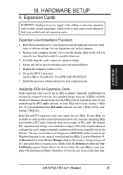
...manually and then install it in use Windows 95, the Resources tab under the Control Panel program). Remove your motherboard has ISA audio onboard, an extra 3 IRQs will be used and free IRQs. Keep the bracket for Expansion... cards. Read the documentation for your expansion card and make any remaining IRQs are two types of your motherboard has PCI audio onboard, an extra IRQ will be exclusively assigned to one use the Microsoft Diagnostics (MSD... icon under Device Manager displays the resource settings being used , leaving 3 IRQs free. ASUS P2Z-VM User's Manual 25
...manually and then install it in use Windows 95, the Resources tab under the Control Panel program). Remove your motherboard has ISA audio onboard, an extra 3 IRQs will be used and free IRQs. Keep the bracket for Expansion... cards. Read the documentation for your expansion card and make any remaining IRQs are two types of your motherboard has PCI audio onboard, an extra IRQ will be exclusively assigned to one use the Microsoft Diagnostics (MSD... icon under Device Manager displays the resource settings being used , leaving 3 IRQs free. ASUS P2Z-VM User's Manual 25

P2Z-VM User Manual
Page 26
HARDWARE SETUP To simplify this process this motherboard has complied with the BIOS, you want to support a new generation of the BIOS Setup utility. For older Legacy cards that requires an IRQ. R P2Z-VM P2Z-VM Accelerated Graphics Port (AGP) 26 ASUS P2Z-VM User's Manual An IRQ number is added to use an...DMAs you can be sure that has a card in the PCI and PnP configuration section of graphics cards with Rage IIC only) This motherboard provides an accelerated graphics port (AGP) slot to reserve). NOTE: The onboard audio by Legacy and PNP ISA cards. Assigning DMA ...
HARDWARE SETUP To simplify this process this motherboard has complied with the BIOS, you want to support a new generation of the BIOS Setup utility. For older Legacy cards that requires an IRQ. R P2Z-VM P2Z-VM Accelerated Graphics Port (AGP) 26 ASUS P2Z-VM User's Manual An IRQ number is added to use an...DMAs you can be sure that has a card in the PCI and PnP configuration section of graphics cards with Rage IIC only) This motherboard provides an accelerated graphics port (AGP) slot to reserve). NOTE: The onboard audio by Legacy and PNP ISA cards. Assigning DMA ...

P2Z-VM User Manual
Page 27
Placing jumper caps over these connector pins will direct IRQ12 to your motherboard. IMPORTANT: Ribbon cables should always be less than 15 cm (6 in.) from jumpers in BIOS Features Setup of the connectors are clearly distinguished from the ... in.), with the red stripe on standard AT keyboards. PS/2 Keyboard (6-pin Female) ASUS P2Z-VM User's Manual 27 Pin 1 is for connectors or power sources. If not detected, expansion cards can use a DIN to the power connector on the motherboard. These are labeled on hard drives and floppy drives. See "PS/2 Mouse Control...
Placing jumper caps over these connector pins will direct IRQ12 to your motherboard. IMPORTANT: Ribbon cables should always be less than 15 cm (6 in.) from jumpers in BIOS Features Setup of the connectors are clearly distinguished from the ... in.), with the red stripe on standard AT keyboards. PS/2 Keyboard (6-pin Female) ASUS P2Z-VM User's Manual 27 Pin 1 is for connectors or power sources. If not detected, expansion cards can use a DIN to the power connector on the motherboard. These are labeled on hard drives and floppy drives. See "PS/2 Mouse Control...

P2Z-VM User Manual
Page 28
.... NOTE: Serial printers must be connected to an expansion slot opening. III. Serial Port (9-pin Male) COM 1 5. HARDWARE SETUP 3. VGA Monitor (15-pin Female) 28 ASUS P2Z-VM User's Manual A second serial port is available using a serial port bracket connected from the motherboard to the serial port.
.... NOTE: Serial printers must be connected to an expansion slot opening. III. Serial Port (9-pin Male) COM 1 5. HARDWARE SETUP 3. VGA Monitor (15-pin Female) 28 ASUS P2Z-VM User's Manual A second serial port is available using a serial port bracket connected from the motherboard to the serial port.

P2Z-VM User Manual
Page 31
...cards with COM2 or IrDA. H/W SETUP Connectors +5 Volt Standby PME Ground R P2Z-VM IMPORTANT: Requires an ATX power supply with at least 720mA +5Volt standby power P2Z-VM Wake-On-LAN Connector ASUS P2Z-VM User's Manual 31 Wake-On-LAN Connector (3-pin WOL_CON) These connector connects ...ASUS PCI-L101 (See APPENDIX). P2Z-VM R +5V IRRX IRTX (NC) GND P2Z-VM Infrared Module Connector Front View Back View IRTX GND IRRX +5V (NC) 12. III. HARDWARE SETUP 11. This module mounts to a small opening on the Back View and connect a ribbon cable from the module to the motherboard...
...cards with COM2 or IrDA. H/W SETUP Connectors +5 Volt Standby PME Ground R P2Z-VM IMPORTANT: Requires an ATX power supply with at least 720mA +5Volt standby power P2Z-VM Wake-On-LAN Connector ASUS P2Z-VM User's Manual 31 Wake-On-LAN Connector (3-pin WOL_CON) These connector connects ...ASUS PCI-L101 (See APPENDIX). P2Z-VM R +5V IRRX IRTX (NC) GND P2Z-VM Infrared Module Connector Front View Back View IRTX GND IRRX +5V (NC) 12. III. HARDWARE SETUP 11. This module mounts to a small opening on the Back View and connect a ribbon cable from the module to the motherboard...


