P2B-S User Manual
Page 1
R P2B-L / P2B-S / P2B-LS Pentium® II Motherboards USER'S MANUAL Special Features ASUS P2B-L (power supply must provide at least 720mA on the +5VSB) • Intel 82558 LAN Chipset • Wake-On-LAN ASUS P2B-S • Adaptec 7890 SCSI Chipset • Adaptec 3860 SCSI Transceiver ASUS P2B-LS (power supply must provide at least 720mA on the +5VSB) • Intel 82558 LAN Chipset • Wake-On-LAN • Adaptec 7890 SCSI Chipset • Adaptec 3860 SCSI Transceiver
R P2B-L / P2B-S / P2B-LS Pentium® II Motherboards USER'S MANUAL Special Features ASUS P2B-L (power supply must provide at least 720mA on the +5VSB) • Intel 82558 LAN Chipset • Wake-On-LAN ASUS P2B-S • Adaptec 7890 SCSI Chipset • Adaptec 3860 SCSI Transceiver ASUS P2B-LS (power supply must provide at least 720mA on the +5VSB) • Intel 82558 LAN Chipset • Wake-On-LAN • Adaptec 7890 SCSI Chipset • Adaptec 3860 SCSI Transceiver

P2B-S User Manual
Page 5
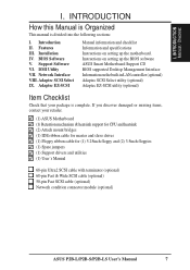
...CD Main Menu 58 Main Menu Selections 59 Other CD Directories 59 VI. ADAPTEC EZ-SCSI UTILITY Quick Start Instructions 79 Troubleshooting Tips 80 Information for Novell 65 Windows NT Server...(optional 69 Troubleshooting 71 Technical Information 74 Using Wake On LAN 75 Glossary 76 VIII. ADAPTEC SCSI SELECT Configuring the SCSI Adapter 77 SCSI Disk Utilities 77 IX. DMI Utility Desktop Management Interface (DMI 60 VII. CONTENTS PNP and PCI... Formatting Utilities 84 Low-level Formatter (scsifmt 84 Formatter and Partitioner (afdisk 85 ASUS P2B-L/P2B-S/P2B-LS User's Manual 5
...CD Main Menu 58 Main Menu Selections 59 Other CD Directories 59 VI. ADAPTEC EZ-SCSI UTILITY Quick Start Instructions 79 Troubleshooting Tips 80 Information for Novell 65 Windows NT Server...(optional 69 Troubleshooting 71 Technical Information 74 Using Wake On LAN 75 Glossary 76 VIII. ADAPTEC SCSI SELECT Configuring the SCSI Adapter 77 SCSI Disk Utilities 77 IX. DMI Utility Desktop Management Interface (DMI 60 VII. CONTENTS PNP and PCI... Formatting Utilities 84 Low-level Formatter (scsifmt 84 Formatter and Partitioner (afdisk 85 ASUS P2B-L/P2B-S/P2B-LS User's Manual 5
P2B-S User Manual
Page 7
... floppy and (2) 3.5inch floppies (1) Spare jumpers (1) Support drivers and utilities (1) User's Manual 68-pin Ultra2 SCSI cable with terminator (optional) 68-pin Fast & Wide SCSI cable (optional) 50-pin Fast SCSI cable (optional) Network condition connector module (optional) ASUS P2B-L/P2B-S/P2B-LS User's Manual 7 Support Software VI. Network Interface VIII. Introduction II. If you discover damaged...
... floppy and (2) 3.5inch floppies (1) Spare jumpers (1) Support drivers and utilities (1) User's Manual 68-pin Ultra2 SCSI cable with terminator (optional) 68-pin Fast & Wide SCSI cable (optional) 50-pin Fast SCSI cable (optional) Network condition connector module (optional) ASUS P2B-L/P2B-S/P2B-LS User's Manual 7 Support Software VI. Network Interface VIII. Introduction II. If you discover damaged...
P2B-S User Manual
Page 8
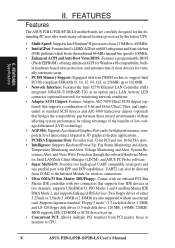
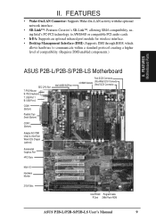
FEATURES Features The ASUS P2B-L/P2B-S/P2B-LS motherboards are carefully designed for the demanding PC... Resources Alert, and Virus Write Protection through the onboard Hardware Monitor, Intel LANDesk Client Manager (LDCM), and ASUS PC Probe software. • Super Multi-I/O: Provides two high-speed UART compatible serial ports and one parallel...drives (3.5-inch disk drive: 120 MB, 1.44MB, 720KB). II. BIOS supports IDE CD-ROM or SCSI device boot-up to CPU. 8 ASUS P2B-L/P2B-S/P2B-LS User's Manual FEATURES Specifications II. UART2 can also be directed from PCI master buses to memory ...
FEATURES Features The ASUS P2B-L/P2B-S/P2B-LS motherboards are carefully designed for the demanding PC... Resources Alert, and Virus Write Protection through the onboard Hardware Monitor, Intel LANDesk Client Manager (LDCM), and ASUS PC Probe software. • Super Multi-I/O: Provides two high-speed UART compatible serial ports and one parallel...drives (3.5-inch disk drive: 120 MB, 1.44MB, 720KB). II. BIOS supports IDE CD-ROM or SCSI device boot-up to CPU. 8 ASUS P2B-L/P2B-S/P2B-LS User's Manual FEATURES Specifications II. UART2 can also be directed from PCI master buses to memory ...
P2B-S User Manual
Page 9
...) Serial (Bottom) COM 2 (Bottom) Intel 440BX AGPset Fast-SCSI Connector 4 DIMM Sockets Ultra-Wide SCSI Connector Ultra2 SCSI Connector Adaptec AIC-7890 Ultra2 & Ultra-Fast/ Wide SCSI Chipset (optional) Accelerated Graphics Port 4PCI Slots Multi-I/O Hardware Monitor 2 ISA Slots Intel PIIX4E Programmable PCIset 2Mbit Flash ROM ASUS P2B-L/P2B-S/P2B-LS User's Manual 9 FEATURES • Wake-On-LAN...
...) Serial (Bottom) COM 2 (Bottom) Intel 440BX AGPset Fast-SCSI Connector 4 DIMM Sockets Ultra-Wide SCSI Connector Ultra2 SCSI Connector Adaptec AIC-7890 Ultra2 & Ultra-Fast/ Wide SCSI Chipset (optional) Accelerated Graphics Port 4PCI Slots Multi-I/O Hardware Monitor 2 ISA Slots Intel PIIX4E Programmable PCIset 2Mbit Flash ROM ASUS P2B-L/P2B-S/P2B-LS User's Manual 9 FEATURES • Wake-On-LAN...

P2B-S User Manual
Page 10
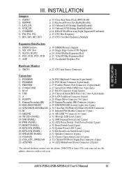
...of purchase. INSTALLATION Board Layout 10 ASUS P2B-L/P2B-S/P2B-LS User's Manual FS0 68 34 34 68 COM 2 RJ-45 FLOPPY LAN Activity LED Connector 35 1 35 1 50-Pin SCSI 1 1 68-Pin Wide SCSI 68-Pin Ultra2 SCSI Intel 82558 Ethernet LAN Controller Accelerated Graphics...Multi-I/O PCI Slot 2 Hardware Monitor PCI Slot 1 ISA Slot 1 ISA Slot 2 SCSI_EN Adaptec SCSI Chipset Adaptec AIC-3860 Chipset SECONDARY IDE 1 PRIMARY IDE Intel PIIX4E Chipset CLRTC 1 Freq. INSTALLATION ASUS P2B-L/P2B-S/P2B-LS Motherboard Layout DIMM Socket 0 (64/72 bit, 168 pin module) DIMM Socket 1 (64...
...of purchase. INSTALLATION Board Layout 10 ASUS P2B-L/P2B-S/P2B-LS User's Manual FS0 68 34 34 68 COM 2 RJ-45 FLOPPY LAN Activity LED Connector 35 1 35 1 50-Pin SCSI 1 1 68-Pin Wide SCSI 68-Pin Ultra2 SCSI Intel 82558 Ethernet LAN Controller Accelerated Graphics...Multi-I/O PCI Slot 2 Hardware Monitor PCI Slot 1 ISA Slot 1 ISA Slot 2 SCSI_EN Adaptec SCSI Chipset Adaptec AIC-3860 Chipset SECONDARY IDE 1 PRIMARY IDE Intel PIIX4E Chipset CLRTC 1 Freq. INSTALLATION ASUS P2B-L/P2B-S/P2B-LS Motherboard Layout DIMM Socket 0 (64/72 bit, 168 pin module) DIMM Socket 1 (64...
P2B-S User Manual
Page 11
..., BF3 p. 13 Clear Real Time Clock (RTC) RAM p. 13 Keyboard Power Up (Enable/Disable) p. 14 Onboard LAN Setting (Enable/Disable) p. 14 Onboard SCSI Setting (Enable/Disable) p. 14 IDE+SCSI LED Activity Light (Separated/Combined) p. 15 CPU Bus Frequency p. 15 CPU Core:Bus Frequency Multiple Expansion Slots/Sockets 1) DIMM Sockets 2) SEC CPU Slot... Connector (20 pins) *The onboard hardware monitor uses the address 290H-297H so legacy ISA cards must not use this address, otherwise conflicts will occur. ASUS P2B-L/P2B-S/P2B-LS User's Manual 11 III.
..., BF3 p. 13 Clear Real Time Clock (RTC) RAM p. 13 Keyboard Power Up (Enable/Disable) p. 14 Onboard LAN Setting (Enable/Disable) p. 14 Onboard SCSI Setting (Enable/Disable) p. 14 IDE+SCSI LED Activity Light (Separated/Combined) p. 15 CPU Bus Frequency p. 15 CPU Core:Bus Frequency Multiple Expansion Slots/Sockets 1) DIMM Sockets 2) SEC CPU Slot... Connector (20 pins) *The onboard hardware monitor uses the address 290H-297H so legacy ISA cards must not use this address, otherwise conflicts will occur. ASUS P2B-L/P2B-S/P2B-LS User's Manual 11 III.
P2B-S User Manual
Page 12
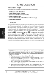
Install Expansion Cards 5. Setup the BIOS Software 1. Jumpers Several hardware settings are separated from the system. 12 ASUS P2B-L/P2B-S/P2B-LS User's Manual The jumper settings will be shown graphi- INSTALLATION Jumpers WARNING! Place components on a grounded antistatic pad or...jumper caps to connect jumper pins (JP) on the board. To connect the pins, simply place a plastic jumper cap over the two pins as SCSI cards, contain very delicate Integrated Circuit (IC) chips. Unplug your computer. 1. Set Jumpers on the inside. 2. To protect them against damage from ...
Install Expansion Cards 5. Setup the BIOS Software 1. Jumpers Several hardware settings are separated from the system. 12 ASUS P2B-L/P2B-S/P2B-LS User's Manual The jumper settings will be shown graphi- INSTALLATION Jumpers WARNING! Place components on a grounded antistatic pad or...jumper caps to connect jumper pins (JP) on the board. To connect the pins, simply place a plastic jumper cap over the two pins as SCSI cards, contain very delicate Integrated Circuit (IC) chips. Unplug your computer. 1. Set Jumpers on the inside. 2. To protect them against damage from ...
P2B-S User Manual
Page 14
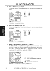
... LAN Setting 4. COMBINE (Default) IDELED and SCSILED activity are separate COMBINE IDELED includes SCSILED activity P2B-L/S/LS IDE/SCSI Device Activity LED Selection 14 ASUS P2B-L/P2B-S/P2B-LS User's Manual INSTALLATION Jumpers III. INSTALLATION 3. Onboard SCSI Setting (SCSI_EN) The onboard Adaptec Fast/Wide/Ultra2 SCSI may be enabled or disabled using this jumper. If you have both...
... LAN Setting 4. COMBINE (Default) IDELED and SCSILED activity are separate COMBINE IDELED includes SCSILED activity P2B-L/S/LS IDE/SCSI Device Activity LED Selection 14 ASUS P2B-L/P2B-S/P2B-LS User's Manual INSTALLATION Jumpers III. INSTALLATION 3. Onboard SCSI Setting (SCSI_EN) The onboard Adaptec Fast/Wide/Ultra2 SCSI may be enabled or disabled using this jumper. If you have both...

P2B-S User Manual
Page 29
...is removed to prevent inserting in the wrong orientation when using one operating system on an IDE drive and another ribbon cable on a SCSI drive and select the boot disk through BIOS Features Setup. TIP: If the case-mounted LED does not light, try reversing the 2-... "HDD Sequence SCSI/IDE First" & "Boot Sequence" in the BIOS Features Setup of your hard disk(s). INSTALLATION 9. III. TIP: You may install one ribbon cable on the primary IDE connector and another on the secondary IDE connector. IDELED SCSILED P2B-L/S/LS IDE/SCSI Device Activity LED R ASUS P2B-L/P2B-S/P2B-LS User's ...
...is removed to prevent inserting in the wrong orientation when using one operating system on an IDE drive and another ribbon cable on a SCSI drive and select the boot disk through BIOS Features Setup. TIP: If the case-mounted LED does not light, try reversing the 2-... "HDD Sequence SCSI/IDE First" & "Boot Sequence" in the BIOS Features Setup of your hard disk(s). INSTALLATION 9. III. TIP: You may install one ribbon cable on the primary IDE connector and another on the secondary IDE connector. IDELED SCSILED P2B-L/S/LS IDE/SCSI Device Activity LED R ASUS P2B-L/P2B-S/P2B-LS User's ...

P2B-S User Manual
Page 30
... end device. INSTALLATION Connectors 35 1 68 34 68-pin Ultra2 SCSI Connector 35 1 68 34 68-pin Wide SCSI Connector 1 50-pin Fast SCSI II Connector P2B-L/S/LS Onboard SCSI Connectors IMPORTANT: The 68-pin Wide SCSI Connector is always terminated and will only work as UltraSCSI, so .... 30 ASUS P2B-L/P2B-S/P2B-LS User's Manual R R III. Fast (50-pin)/Wide (68-pin)/Ultra2 (68-pin) SCSI Connectors This motherboard has onboard 50-Pin Fast SCSI connector for 8-bit SCSI devices, 68-Pin Wide SCSI connector for 16-bit SCSI devices, and 68-Pin Ultra2 SCSI connector for 32-bit SCSI devices. ...
... end device. INSTALLATION Connectors 35 1 68 34 68-pin Ultra2 SCSI Connector 35 1 68 34 68-pin Wide SCSI Connector 1 50-pin Fast SCSI II Connector P2B-L/S/LS Onboard SCSI Connectors IMPORTANT: The 68-pin Wide SCSI Connector is always terminated and will only work as UltraSCSI, so .... 30 ASUS P2B-L/P2B-S/P2B-LS User's Manual R R III. Fast (50-pin)/Wide (68-pin)/Ultra2 (68-pin) SCSI Connectors This motherboard has onboard 50-Pin Fast SCSI connector for 8-bit SCSI devices, 68-Pin Wide SCSI connector for 16-bit SCSI devices, and 68-Pin Ultra2 SCSI connector for 32-bit SCSI devices. ...

P2B-S User Manual
Page 35
...the front of the system case will appear on test. Connect the power cord into the power supply located on the chain) c. External SCSI devices (starting with the last device on the back of your system case according to enter BIOS setup. For ATX power supplies, you ... "green" standards or if it complies with a surge protector. 5. If you can now safely turn on the front panel of the case. 6. ASUS P2B-L/P2B-S/P2B-LS User's Manual 35 INSTALLATION Power Connection Procedures 1. Your system power. NOTE: The message "You can press the ATX power switch after Windows shuts ...
...the front of the system case will appear on test. Connect the power cord into the power supply located on the chain) c. External SCSI devices (starting with the last device on the back of your system case according to enter BIOS setup. For ATX power supplies, you ... "green" standards or if it complies with a surge protector. 5. If you can now safely turn on the front panel of the case. 6. ASUS P2B-L/P2B-S/P2B-LS User's Manual 35 INSTALLATION Power Connection Procedures 1. Your system power. NOTE: The message "You can press the ATX power switch after Windows shuts ...

P2B-S User Manual
Page 41
...23), Minute: (00 to 59), Second: (00 to two hard disks; The onboard PCI IDE connectors provide Primary and Secondary channels for SCSI hard disks need not to the MS-DOS manual. Specifications for connecting up to 59). Follow the hour, minute and second format. The ...support up to four IDE hard disks or other SCSI controller cards, refer to their respective documentations on how to create this file, please refer to be used with the information regarding the drive specifications. BIOS Standard CMOS ASUS P2B-L/P2B-S/P2B-LS User's Manual 41 the first of sectors...
...23), Minute: (00 to 59), Second: (00 to two hard disks; The onboard PCI IDE connectors provide Primary and Secondary channels for SCSI hard disks need not to the MS-DOS manual. Specifications for connecting up to 59). Follow the hour, minute and second format. The ...support up to four IDE hard disks or other SCSI controller cards, refer to their respective documentations on how to create this file, please refer to be used with the information regarding the drive specifications. BIOS Standard CMOS ASUS P2B-L/P2B-S/P2B-LS User's Manual 41 the first of sectors...

P2B-S User Manual
Page 44
...once. Boot Sequence (A,C) This field determines where the system looks first for this field is always the boot disk using a SCSI hard disk drive. F,A; and C,A. Most IDE drives, except older versions, can utilize this feature may decrease system performance. ...SCSI. Selections are A,C; Options are HDD MAX, Disabled, 2, 4, 8, 16, and 32. A,CDROM,C; Setup default setting for an operating system. IDE HDD Block Mode Sectors (HDD MAX) This field enhances hard disk performance by skipping retesting a second, third, and forth time. BIOS BIOS Features 44 ASUS P2B-L/P2B-S/P2B...
...once. Boot Sequence (A,C) This field determines where the system looks first for this field is always the boot disk using a SCSI hard disk drive. F,A; and C,A. Most IDE drives, except older versions, can utilize this feature may decrease system performance. ...SCSI. Selections are A,C; Options are HDD MAX, Disabled, 2, 4, 8, 16, and 32. A,CDROM,C; Setup default setting for an operating system. IDE HDD Block Mode Sectors (HDD MAX) This field enhances hard disk performance by skipping retesting a second, third, and forth time. BIOS BIOS Features 44 ASUS P2B-L/P2B-S/P2B...

P2B-S User Manual
Page 48
...+EPP) This field allows you to reverse the hardware drive letter assignments of Auto will no longer work if you install an I/O card with only SCSI drives). Onboard PCI IDE Enable (Both) You can select either DMA Channel 1, 3, or Disable. IDE 0 Master/Slave PIO/DMA Mode, IDE... transfer speeds and data integrity) for the onboard serial connector. ECP+EPP allows normal speed operation in one direction only; BIOS Chipset Features 48 ASUS P2B-L/P2B-S/P2B-LS User's Manual Onboard Serial Port 2 (2F8H/IRQ3) Settings are available: No Swap and Swap AB. IV. Two options are 3F8H/IRQ4...
...+EPP) This field allows you to reverse the hardware drive letter assignments of Auto will no longer work if you install an I/O card with only SCSI drives). Onboard PCI IDE Enable (Both) You can select either DMA Channel 1, 3, or Disable. IDE 0 Master/Slave PIO/DMA Mode, IDE... transfer speeds and data integrity) for the onboard serial connector. ECP+EPP allows normal speed operation in one direction only; BIOS Chipset Features 48 ASUS P2B-L/P2B-S/P2B-LS User's Manual Onboard Serial Port 2 (2F8H/IRQ3) Settings are available: No Swap and Swap AB. IV. Two options are 3F8H/IRQ4...

P2B-S User Manual
Page 50
This feature does not affect SCSI hard drives. The Soft-Off mode refers to powering off the system through a momentary button switch (ATX switch) or through the software as a normal system ... Power Down", which places the hard disk into its lowest power consumption mode, and the "Suspend Mode" which each of inactivity. BIOS Power Management 50 ASUS P2B-L/P2B-S/P2B-LS User's Manual The DPMS (Display Power Management System) features allow the BIOS to control the video display card if it is started or restarted...
This feature does not affect SCSI hard drives. The Soft-Off mode refers to powering off the system through a momentary button switch (ATX switch) or through the software as a normal system ... Power Down", which places the hard disk into its lowest power consumption mode, and the "Suspend Mode" which each of inactivity. BIOS Power Management 50 ASUS P2B-L/P2B-S/P2B-LS User's Manual The DPMS (Display Power Management System) features allow the BIOS to control the video display card if it is started or restarted...

P2B-S User Manual
Page 53
... increase the block size to Yes. The default for Ultra2 devices, such as scanners, CD-ROMs, or tape drives. BIOS Plug & Play / PCI ASUS P2B-L/P2B-S/P2B-LS User's Manual 53 Available options include: No/ICU and Yes. If you have such a card, and you do not want to use this task..., leave ISA MEM Block BASE to enable or disable the onboard termination for the onboard Adaptec 7890 SCSI BIOS. ONB SCSI LVD Term. (Enabled) This allows you to its address range, select a base address from functioning. Onboard AHA BIOS (Auto) The default ...
... increase the block size to Yes. The default for Ultra2 devices, such as scanners, CD-ROMs, or tape drives. BIOS Plug & Play / PCI ASUS P2B-L/P2B-S/P2B-LS User's Manual 53 Available options include: No/ICU and Yes. If you have such a card, and you do not want to use this task..., leave ISA MEM Block BASE to enable or disable the onboard termination for the onboard Adaptec 7890 SCSI BIOS. ONB SCSI LVD Term. (Enabled) This allows you to its address range, select a base address from functioning. Onboard AHA BIOS (Auto) The default ...
P2B-S User Manual
Page 59
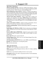
.... Please view the user's manual in Adobe Acrobat PDF format located in the "\SCSI" directory. ASUS PC Probe Setup (\ASUSLM): Installs a simple utility to view the Technical Support Form (with a text editor, such as Notepad). Various ... additional notes concerning this CD. BusMaster (\BUSMASTR): Installs the Intel BusMaster IDE drivers for installing network on the ASUS Support CD. Exit: Exit the current menu. SUPPORT S/W ASUS Smart Motherbaord ASUS P2B-L/P2B-S/P2B-LS User's Manual 59 Other CD Directories \AFLASH: Utility for updating your system. Browse this CD: View the...
.... Please view the user's manual in Adobe Acrobat PDF format located in the "\SCSI" directory. ASUS PC Probe Setup (\ASUSLM): Installs a simple utility to view the Technical Support Form (with a text editor, such as Notepad). Various ... additional notes concerning this CD. BusMaster (\BUSMASTR): Installs the Intel BusMaster IDE drivers for installing network on the ASUS Support CD. Exit: Exit the current menu. SUPPORT S/W ASUS Smart Motherbaord ASUS P2B-L/P2B-S/P2B-LS User's Manual 59 Other CD Directories \AFLASH: Utility for updating your system. Browse this CD: View the...

P2B-S User Manual
Page 77
.... Instructions on how to use this function. This utility is only necessary if you the option of reassigning bad blocks so that your SCSI hard disks. SCSI SELECT Configuring SCSI ASUS P2B-L/P2B-S/P2B-LS User's Manual 77 scans the selected drive media for hard disk drives only and will have already been low-level formatted when...
.... Instructions on how to use this function. This utility is only necessary if you the option of reassigning bad blocks so that your SCSI hard disks. SCSI SELECT Configuring SCSI ASUS P2B-L/P2B-S/P2B-LS User's Manual 77 scans the selected drive media for hard disk drives only and will have already been low-level formatted when...

P2B-S User Manual
Page 79
...type a:\install (assuming your CDROM drive, follow the instructions for your floppy disk drive. 3. Follow the onscreen instructions. EZ-SCSI UTILITY Intro/Quick Start ASUS P2B-L/P2B-S/P2B-LS User's Manual 79 IX. We recommend that after you install Adaptec EZSCSI you need to your 3.5" floppy is A:... drive. IX. Then click OK. 5. Insert the Adaptec EZSCSI Setup Disk into your operating system software in one of SCSI. ADAPTEC EZ-SCSI UTILITY Welcome to learn more about the features of the following sections. Then follow the DOS Quick Start instructions below. Insert...
...type a:\install (assuming your CDROM drive, follow the instructions for your floppy disk drive. 3. Follow the onscreen instructions. EZ-SCSI UTILITY Intro/Quick Start ASUS P2B-L/P2B-S/P2B-LS User's Manual 79 IX. We recommend that after you install Adaptec EZSCSI you need to your 3.5" floppy is A:... drive. IX. Then click OK. 5. Insert the Adaptec EZSCSI Setup Disk into your operating system software in one of SCSI. ADAPTEC EZ-SCSI UTILITY Welcome to learn more about the features of the following sections. Then follow the DOS Quick Start instructions below. Insert...