NRL-LS User Manual
Page 9
...About this guide is organized This manual contains the following parts: • Chapter 1: Product introduction This chapter describes the features of the NRL-LS motherboard. It includes brief descriptions of the special attributes of the switches, jumpers, and connectors on the motherboard. • Chapter 3: Powering.... • Chapter 2: Hardware information This chapter lists the hardware setup procedures that you need when installing the ASUS NRL-LS motherboard. How this guide This user guide contains the information you have to perform when installing system components.
...About this guide is organized This manual contains the following parts: • Chapter 1: Product introduction This chapter describes the features of the NRL-LS motherboard. It includes brief descriptions of the special attributes of the switches, jumpers, and connectors on the motherboard. • Chapter 3: Powering.... • Chapter 2: Hardware information This chapter lists the hardware setup procedures that you need when installing the ASUS NRL-LS motherboard. How this guide This user guide contains the information you have to perform when installing system components.
NRL-LS User Manual
Page 14
Chapter summary 1.1 Welcome 1-1 1.2 Package contents 1-1 1.3 Special features 1-2 1.4 Motherboard overview 1-6 ASUS NRL-LS motherboard
Chapter summary 1.1 Welcome 1-1 1.2 Package contents 1-1 1.3 Special features 1-2 1.4 Motherboard overview 1-6 ASUS NRL-LS motherboard
NRL-LS User Manual
Page 15
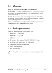
... your NRL-LS package for the following items. ASUS NRL-LS motherboard ASUS NRL-LS support CD I/O shield 80-conductor ribbon cable for UltraDMA100/66//33 IDE drives 68-pin LVD SCSI cable for Ultra 160 SCSI devices Ribbon cable for buying the ASUS® NRL-LS motherboard! ASUS NRL-LS motherboard ...user guide 1-1 Thank you start installing the motherboard, and hardware devices on it another standout in your retailer. The ASUS NRL-LS motherboard delivers a host of new features and...
... your NRL-LS package for the following items. ASUS NRL-LS motherboard ASUS NRL-LS support CD I/O shield 80-conductor ribbon cable for UltraDMA100/66//33 IDE drives 68-pin LVD SCSI cable for Ultra 160 SCSI devices Ribbon cable for buying the ASUS® NRL-LS motherboard! ASUS NRL-LS motherboard ...user guide 1-1 Thank you start installing the motherboard, and hardware devices on it another standout in your retailer. The ASUS NRL-LS motherboard delivers a host of new features and...
NRL-LS User Manual
Page 17
Onboard VGA The ATI Rage-XL PCI-based VGA controller integrates an 8MB display SDRAM to support 10/100/1000 Mbit/sec transfer rates for a high-speed and highly-compatible network connection. ASUS NRL-LS motherboard user guide 1-3 Onboard LAN The motherboard features the Intel® 82540EM Gigabit Ethernet controller to provide onboard video solution.
Onboard VGA The ATI Rage-XL PCI-based VGA controller integrates an 8MB display SDRAM to support 10/100/1000 Mbit/sec transfer rates for a high-speed and highly-compatible network connection. ASUS NRL-LS motherboard user guide 1-3 Onboard LAN The motherboard features the Intel® 82540EM Gigabit Ethernet controller to provide onboard video solution.
NRL-LS User Manual
Page 19
.... Compliance Both the BIOS and the hardware levels of the motherboard meet the stringent requirements for Windows NT/2000/XP. ASUS NRL-LS motherboard user guide 1-5 Auto fan off The system fans power off automatically when the system is in the system memory for more control and protection ...
.... Compliance Both the BIOS and the hardware levels of the motherboard meet the stringent requirements for Windows NT/2000/XP. ASUS NRL-LS motherboard user guide 1-5 Auto fan off The system fans power off automatically when the system is in the system memory for more control and protection ...
NRL-LS User Manual
Page 21
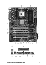
1 23 4 5 24 6 23 7 22 21 8 9 20 19 18 17 16 15 14 13 12 11 10 25 26 31 30 29 28 27 ASUS NRL-LS motherboard user guide 1-7
1 23 4 5 24 6 23 7 22 21 8 9 20 19 18 17 16 15 14 13 12 11 10 25 26 31 30 29 28 27 ASUS NRL-LS motherboard user guide 1-7
NRL-LS User Manual
Page 23
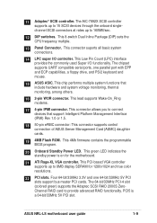
... Management Card (ASMC) daughter cards. 19 4MB Flash ROM. PCI5 is on for 1280x1024 and true color resolutions. 22 PCI slots. ASUS NRL-LS motherboard user guide 1-9 This green LED indicates the standby power is a 64-bit/33MHz 5V PCI slot. The chipset supports UART compatible serial ports, one ... 2-pin WOR connector. Four 64-bit/33MHz 3.3V and one parallel port with EPP and ECP capabilities, a floppy drive, and PS/2 keyboard and mouse. 15 ASUS ASIC.
... Management Card (ASMC) daughter cards. 19 4MB Flash ROM. PCI5 is on for 1280x1024 and true color resolutions. 22 PCI slots. ASUS NRL-LS motherboard user guide 1-9 This green LED indicates the standby power is a 64-bit/33MHz 5V PCI slot. The chipset supports UART compatible serial ports, one ... 2-pin WOR connector. Four 64-bit/33MHz 3.3V and one parallel port with EPP and ECP capabilities, a floppy drive, and PS/2 keyboard and mouse. 15 ASUS ASIC.
NRL-LS User Manual
Page 26
Chapter summary 2.1 Motherboard installation 2-1 2.2 Motherboard layout 2-2 2.3 Before you proceed 2-3 2.4 Central Processing Unit (CPU 2-4 2.5 System memory 2-8 2.6 Expansion slots 2-11 2.7 Switches and jumpers 2-14 2.8 Connectors 2-17 ASUS NRL-LS motherboard
Chapter summary 2.1 Motherboard installation 2-1 2.2 Motherboard layout 2-2 2.3 Before you proceed 2-3 2.4 Central Processing Unit (CPU 2-4 2.5 System memory 2-8 2.6 Expansion slots 2-11 2.7 Switches and jumpers 2-14 2.8 Connectors 2-17 ASUS NRL-LS motherboard
NRL-LS User Manual
Page 27
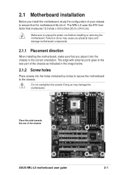
... as indicated in the correct orientation. Make sure to unplug the power cord before installing or removing the motherboard. The NRL-LS uses the ATX form factor that you install the motherboard, study the configuration of the chassis ASUS NRL-LS motherboard user guide 2-1 2.1 Motherboard installation Before you place it . Do not overtighten the screws!
... as indicated in the correct orientation. Make sure to unplug the power cord before installing or removing the motherboard. The NRL-LS uses the ATX form factor that you install the motherboard, study the configuration of the chassis ASUS NRL-LS motherboard user guide 2-1 2.1 Motherboard installation Before you place it . Do not overtighten the screws!
NRL-LS User Manual
Page 29
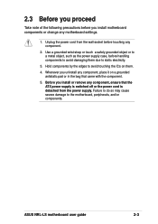
ASUS NRL-LS motherboard user guide 2-3 Hold components by the edges to avoid touching the ICs on a grounded antistatic pad or in the bag that the ATX power ...
ASUS NRL-LS motherboard user guide 2-3 Hold components by the edges to avoid touching the ICs on a grounded antistatic pad or in the bag that the ATX power ...
NRL-LS User Manual
Page 31
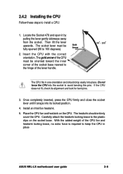
... the socket base. 2.4.2 Installing the CPU Follow these steps to the plastic clips on the CPU. Gold Arrow 90 - 100 The CPU fits in place ASUS NRL-LS motherboard user guide 2-5 The gold arrow of the CPU must be oriented toward the inner corner of the socket base nearest to avoid bending the...
... the socket base. 2.4.2 Installing the CPU Follow these steps to the plastic clips on the CPU. Gold Arrow 90 - 100 The CPU fits in place ASUS NRL-LS motherboard user guide 2-5 The gold arrow of the CPU must be oriented toward the inner corner of the socket base nearest to avoid bending the...
NRL-LS User Manual
Page 33
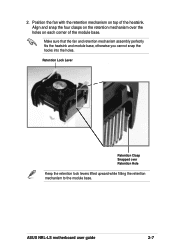
Align and snap the four clasps on the retention mechanism over Retention Hole Keep the retention lock levers lifted upward while fitting the retention mechanism to the module base. ASUS NRL-LS motherboard user guide 2-7 Retention Lock Lever Retention Clasp Snapped over the holes on top of the module base. Make sure that the fan and retention mechanism assembly perfectly fits the heatsink and module base, otherwise you cannot snap the hooks into the holes. Position the fan with the retention mechanism on each corner of the heatsink. 2.
Align and snap the four clasps on the retention mechanism over Retention Hole Keep the retention lock levers lifted upward while fitting the retention mechanism to the module base. ASUS NRL-LS motherboard user guide 2-7 Retention Lock Lever Retention Clasp Snapped over the holes on top of the module base. Make sure that the fan and retention mechanism assembly perfectly fits the heatsink and module base, otherwise you cannot snap the hooks into the holes. Position the fan with the retention mechanism on each corner of the heatsink. 2.
NRL-LS User Manual
Page 35
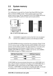
... to 4GB system memory using 184-pin registered PC2100/1600 DIMMs with Serial Presence Detect (SPD) and Error Check and Correction (ECC). ® NRL-LS 104 Pins 80 Pins NRL-LS 184-Pin DDR DIMM Sockets A DDR DIMM is keyed with a notch so that it has a 184-pin footprint compared to the 168-pin... Inline Memory Module (DIMM) sockets. 2.5 System memory 2.5.1 Overview The motherboard comes with SDR, and should be installed only in a socket specially designed for DDR DIMMs. ASUS NRL-LS motherboard user guide 2-9
... to 4GB system memory using 184-pin registered PC2100/1600 DIMMs with Serial Presence Detect (SPD) and Error Check and Correction (ECC). ® NRL-LS 104 Pins 80 Pins NRL-LS 184-Pin DDR DIMM Sockets A DDR DIMM is keyed with a notch so that it has a 184-pin footprint compared to the 168-pin... Inline Memory Module (DIMM) sockets. 2.5 System memory 2.5.1 Overview The motherboard comes with SDR, and should be installed only in a socket specially designed for DDR DIMMs. ASUS NRL-LS motherboard user guide 2-9
NRL-LS User Manual
Page 37
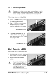
... severe damage to unlock the DIMM. 2. Simultaneously press the retaining clips outward to both the motherboard and the components. Remove the DIMM from the socket. ASUS NRL-LS motherboard user guide 2-11 Firmly insert the DIMM into the socket until the retaining clips snap back in place and the DIMM is properly seated...
... severe damage to unlock the DIMM. 2. Simultaneously press the retaining clips outward to both the motherboard and the components. Remove the DIMM from the socket. ASUS NRL-LS motherboard user guide 2-11 Firmly insert the DIMM into the socket until the retaining clips snap back in place and the DIMM is properly seated...
NRL-LS User Manual
Page 39
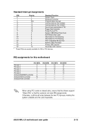
... or PCI devices. PCI INTC 13 14 15 8 9 - - - Otherwise, conflicts will arise between the two PCI groups, making the system unstable and the card inoperable. ASUS NRL-LS motherboard user guide 2-13 Standard Interrupt Assignments IRQ Priority Standard Function 0 1 System Timer 1 2 Keyboard Controller 2 N/A Programmable Interrupt 3* 11 Communications Port (COM2) 4* 12 Communications Port (COM1...
... or PCI devices. PCI INTC 13 14 15 8 9 - - - Otherwise, conflicts will arise between the two PCI groups, making the system unstable and the card inoperable. ASUS NRL-LS motherboard user guide 2-13 Standard Interrupt Assignments IRQ Priority Standard Function 0 1 System Timer 1 2 Keyboard Controller 2 N/A Programmable Interrupt 3* 11 Communications Port (COM2) 4* 12 Communications Port (COM1...
NRL-LS User Manual
Page 41
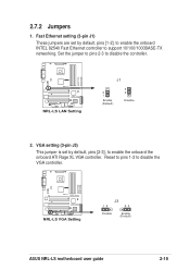
Reset to pins 1-2 to disable the controller. ® NRL-LS NRL-LS LAN Setting J1 2 1 Enable (Default) 3 2 Disable 2. VGA setting (3-pin J3) This jumper is set by default, pins [2-3], to support 10/100/1000BASE-TX networking. Fast ... Fast Ethernet controller to enable the onboard the onboard ATI Rage XL VGA controller. Set the jumper to pins 2-3 to disable the VGA controller. ® NRL-LS NRL-LS VGA Setting J3 12 23 Disable Enable (Default) ASUS NRL-LS motherboard user guide 2-15 2.7.2 Jumpers 1.
Reset to pins 1-2 to disable the controller. ® NRL-LS NRL-LS LAN Setting J1 2 1 Enable (Default) 3 2 Disable 2. VGA setting (3-pin J3) This jumper is set by default, pins [2-3], to support 10/100/1000BASE-TX networking. Fast ... Fast Ethernet controller to enable the onboard the onboard ATI Rage XL VGA controller. Set the jumper to pins 2-3 to disable the VGA controller. ® NRL-LS NRL-LS VGA Setting J3 12 23 Disable Enable (Default) ASUS NRL-LS motherboard user guide 2-15 2.7.2 Jumpers 1.
NRL-LS User Manual
Page 43
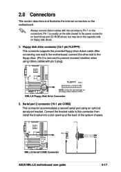
... connectors on the side closest to this connector then install the bracket into a slot opening at the back of the system chassis. ® NRL-LS PIN 1 NRL-LS Serial COM2 Connector ASUS NRL-LS motherboard user guide 2-17 After connecting one end to the motherboard, connect the other end to the floppy drive. (Pin 5 is usually on...
... connectors on the side closest to this connector then install the bracket into a slot opening at the back of the system chassis. ® NRL-LS PIN 1 NRL-LS Serial COM2 Connector ASUS NRL-LS motherboard user guide 2-17 After connecting one end to the motherboard, connect the other end to the floppy drive. (Pin 5 is usually on...
NRL-LS User Manual
Page 45
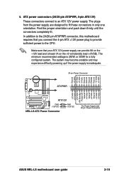
... Connector +3 Volts +12 Volts +12 Volts +5V Standby Power OK Ground +5 Volts Ground +5 Volts Ground +3 Volts +3 Volts 1 For Power Supply with 20-pin Power Connector ASUS NRL-LS motherboard user guide 2-19 The system may become unstable and may experience difficulty powering up if the power supply is 250W, or 300W for a fully...
... Connector +3 Volts +12 Volts +12 Volts +5V Standby Power OK Ground +5 Volts Ground +5 Volts Ground +3 Volts +3 Volts 1 For Power Supply with 20-pin Power Connector ASUS NRL-LS motherboard user guide 2-19 The system may become unstable and may experience difficulty powering up if the power supply is 250W, or 300W for a fully...
NRL-LS User Manual
Page 47
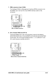
...-4) The 64-bit/33MHz PCI-4 slot (colored green) supports the Adaptec SCSI RAID 2000S Zero-Channel RAID card to this connector. ® NRL-LS IPMIDATA GND IPMICLK NC NRL-LS IPMI Connector CON2 8. The card supports RAID levels 0, 1, 5, multilevel 0/1 and 0/5, cache memory modules with ECC. ® NRL-LS NRL-LS Zero Channel RAID Slot ASUS NRL-LS motherboard user guide 2-21
...-4) The 64-bit/33MHz PCI-4 slot (colored green) supports the Adaptec SCSI RAID 2000S Zero-Channel RAID card to this connector. ® NRL-LS IPMIDATA GND IPMICLK NC NRL-LS IPMI Connector CON2 8. The card supports RAID levels 0, 1, 5, multilevel 0/1 and 0/5, cache memory modules with ECC. ® NRL-LS NRL-LS Zero Channel RAID Slot ASUS NRL-LS motherboard user guide 2-21

NRL-LS User Manual
Page 49
...the bus defaults to 15 devices) 68-pin Female Terminator NRL-LS SCSI Connection Example ASUS NRL-LS motherboard user guide 2-23 The onboard SCSI chipset incorporates an advanced multimode I/O cell that of the slowest device. ® NRL-LS 68-pin Internal SCSI Cable (Twisted-Pair Ribbon) Internal .... Ultra160, Ultra2, Ultra-Wide). Connect SCSI devices as specified by Ultra160 standards. ® NRL-LS 1 35 SCSI 68-Pin Ultra160/ Ultra2-Wide SCSI Connector 34 68 NRL-LS Onboard SCSI Connectors SCSI Connection Notes This motherboard has one 68-Pin Ultra160 SCSI connectors. One ...
...the bus defaults to 15 devices) 68-pin Female Terminator NRL-LS SCSI Connection Example ASUS NRL-LS motherboard user guide 2-23 The onboard SCSI chipset incorporates an advanced multimode I/O cell that of the slowest device. ® NRL-LS 68-pin Internal SCSI Cable (Twisted-Pair Ribbon) Internal .... Ultra160, Ultra2, Ultra-Wide). Connect SCSI devices as specified by Ultra160 standards. ® NRL-LS 1 35 SCSI 68-Pin Ultra160/ Ultra2-Wide SCSI Connector 34 68 NRL-LS Onboard SCSI Connectors SCSI Connection Notes This motherboard has one 68-Pin Ultra160 SCSI connectors. One ...


