
MEB-VM User Manual
Page 1
R MEB-VM Socket 370 AGP Motherboard USER'S MANUAL
R MEB-VM Socket 370 AGP Motherboard USER'S MANUAL
MEB-VM User Manual
Page 4
... 47 Details of Power Management Setup 47 PNP and PCI Setup 50 Details of the ASUS MEB-VM Motherboard 11 III. Jumpers 14 HARDWARE SETUP Steps 14 2. External Connectors 22 Power Connection Procedures 33...ASUS MEB-VM Motherboard Layout 12 1. Expansion Cards 20 Expansion Card Installation Procedure 20 Assigning IRQs for Expansion Cards 20 Assigning DMA Channels for ISA Cards 21 5. FEATURES 8 The ASUS MEB-VM Motherboard 8 Introduction to ASUS Smart Series Motherboards 9 Parts of PNP and PCI Setup 50 Load BIOS Defaults 52 Load Setup Defaults 52 4 ASUS MEB-VM User's Manual...
... 47 Details of Power Management Setup 47 PNP and PCI Setup 50 Details of the ASUS MEB-VM Motherboard 11 III. Jumpers 14 HARDWARE SETUP Steps 14 2. External Connectors 22 Power Connection Procedures 33...ASUS MEB-VM Motherboard Layout 12 1. Expansion Cards 20 Expansion Card Installation Procedure 20 Assigning IRQs for Expansion Cards 20 Assigning DMA Channels for ISA Cards 21 5. FEATURES 8 The ASUS MEB-VM Motherboard 8 Introduction to ASUS Smart Series Motherboards 9 Parts of PNP and PCI Setup 50 Load BIOS Defaults 52 Load Setup Defaults 52 4 ASUS MEB-VM User's Manual...

MEB-VM User Manual
Page 6
... installation. WARNING! However, there is working. Without sufficient circulation, the processor could overheat and damage both the processor and the motherboard. These limits are designed to Part 15 of Communications. 6 ASUS MEB-VM User's Manual Operation is subject to which can radiate radio frequency energy and, if not installed and used in a residential installation. Be...
... installation. WARNING! However, there is working. Without sufficient circulation, the processor could overheat and damage both the processor and the motherboard. These limits are designed to Part 15 of Communications. 6 ASUS MEB-VM User's Manual Operation is subject to which can radiate radio frequency energy and, if not installed and used in a residential installation. Be...

MEB-VM User Manual
Page 7
... for (1) 5.25" floppy and (2) 3.5" floppies (1) COM2 connector with bracket (1) Bag of spare jumper caps (1) Support CD with drivers and utilities (1) This Motherboard User's Manual ASUS PC100-compliant SDRAM (optional) IrDA-compliant infrared module (optional) ASUS PCI-L101 Wake-On-LAN 10/100 Fast Ethernet Card (optional) ASUS MEB-VM User's Manual 7 Software Setup Information on setting up the...
... for (1) 5.25" floppy and (2) 3.5" floppies (1) COM2 connector with bracket (1) Bag of spare jumper caps (1) Support CD with drivers and utilities (1) This Motherboard User's Manual ASUS PC100-compliant SDRAM (optional) IrDA-compliant infrared module (optional) ASUS PCI-L101 Wake-On-LAN 10/100 Fast Ethernet Card (optional) ASUS MEB-VM User's Manual 7 Software Setup Information on setting up the...
MEB-VM User Manual
Page 8
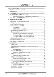
II. FEATURES The ASUS MEB-VM Motherboard The ASUS MEB-VM motherboard is carefully designed for the demanding PC user who wants many intelligent features in a small package. •...serial ports and one parallel port with EPP and ECP capabilities. • Desktop Management Interface (DMI): Supports DMI through an optional ASUS PCI-L101 Fast Ethernet card or a similar ethernet card. • SB-Link™: Features Creative's SB-Link™, allowing ...ATI 3D Rage Pro AGP 2X (8MB SDRAM) or Rage IIC AGP (4MB SDRAM) for wireless interface. 8 ASUS MEB-VM User's Manual FEATURES Features II.
II. FEATURES The ASUS MEB-VM Motherboard The ASUS MEB-VM motherboard is carefully designed for the demanding PC user who wants many intelligent features in a small package. •...serial ports and one parallel port with EPP and ECP capabilities. • Desktop Management Interface (DMI): Supports DMI through an optional ASUS PCI-L101 Fast Ethernet card or a similar ethernet card. • SB-Link™: Features Creative's SB-Link™, allowing ...ATI 3D Rage Pro AGP 2X (8MB SDRAM) or Rage IIC AGP (4MB SDRAM) for wireless interface. 8 ASUS MEB-VM User's Manual FEATURES Features II.

MEB-VM User Manual
Page 9
...is that this new technology is compatible with existing ATA-2 IDE specifications so there is also imple- FEATURES Introduction to ASUS Smart Series Motherboards Performance • ACPI Ready: ACPI (Advanced Configuration and Power Interface) is no need to upgrade current hard drives or... all the energy saving standards. ASUS MEB-VM User's Manual 9 mented on the following high-level goals: Support for Plug and Play compatibility and power management for Windows 95/98/NT. • SDRAM Optimized Performance: ASUS smart series motherboards support the new generation memory, Synchronous...
...is that this new technology is compatible with existing ATA-2 IDE specifications so there is also imple- FEATURES Introduction to ASUS Smart Series Motherboards Performance • ACPI Ready: ACPI (Advanced Configuration and Power Interface) is no need to upgrade current hard drives or... all the energy saving standards. ASUS MEB-VM User's Manual 9 mented on the following high-level goals: Support for Plug and Play compatibility and power management for Windows 95/98/NT. • SDRAM Optimized Performance: ASUS smart series motherboards support the new generation memory, Synchronous...
MEB-VM User Manual
Page 11
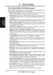
FEATURES Parts of the ASUS MEB-VM Motherboard T: PS/2 Mouse B: PS/2 Keyboard T: USB 1 B: USB 2 Serial COM 1 Parallel Port VGA Connector T: Joystick/Midi B: Out/In/Mic (optional) Wake-On-LAN Header AGP Port 2 PCI ... Chipset Creative Labs PCI Audio (optional) Programmable Intel PIIX4E Flash EEPROM PCIset SB-LinkTM Header 4MB VGA Memory (Rage IIC) 8MB VGA Memory (Rage Pro) ASUS MEB-VM User's Manual 11 FEATURES Motherboard Parts II. II.
FEATURES Parts of the ASUS MEB-VM Motherboard T: PS/2 Mouse B: PS/2 Keyboard T: USB 1 B: USB 2 Serial COM 1 Parallel Port VGA Connector T: Joystick/Midi B: Out/In/Mic (optional) Wake-On-LAN Header AGP Port 2 PCI ... Chipset Creative Labs PCI Audio (optional) Programmable Intel PIIX4E Flash EEPROM PCIset SB-LinkTM Header 4MB VGA Memory (Rage IIC) 8MB VGA Memory (Rage Pro) ASUS MEB-VM User's Manual 11 FEATURES Motherboard Parts II. II.
MEB-VM User Manual
Page 12
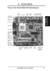
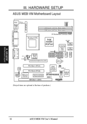
HARDWARE SETUP ASUS MEB-VM Motherboard Layout PS/2 T: Mouse B:Keyboard USB T: Port 1 B:Port 2 COM1 ATXPWR BUS FREQ FS0 FS1 FS2 FS3 FS4 Row DIMM Socket 1 (64/72-bit, 168-pin module) 0 1 ... Slot 1 (PCI1) PCI Slot 2 (PCI2) Multi-I/O & Keyboard Controller 2Mbit Flash EEPROM (Programmable BIOS) ISA Slot 1 (ISA1) Intel PIIX4E Chipset FLOPPY IR SBLINK RTCCLR FREQ MULT ASUS ASIC Buzzer PANEL (Grayed items are optional at the time of purchase.) 12 ASUS MEB-VM User's Manual PARALLEL PORT 01 III. H/W SETUP Motherboard Layout III.
HARDWARE SETUP ASUS MEB-VM Motherboard Layout PS/2 T: Mouse B:Keyboard USB T: Port 1 B:Port 2 COM1 ATXPWR BUS FREQ FS0 FS1 FS2 FS3 FS4 Row DIMM Socket 1 (64/72-bit, 168-pin module) 0 1 ... Slot 1 (PCI1) PCI Slot 2 (PCI2) Multi-I/O & Keyboard Controller 2Mbit Flash EEPROM (Programmable BIOS) ISA Slot 1 (ISA1) Intel PIIX4E Chipset FLOPPY IR SBLINK RTCCLR FREQ MULT ASUS ASIC Buzzer PANEL (Grayed items are optional at the time of purchase.) 12 ASUS MEB-VM User's Manual PARALLEL PORT 01 III. H/W SETUP Motherboard Layout III.

MEB-VM User Manual
Page 14
... components. Place components on a grounded antistatic pad or on the inside. 2. III. Unplug your computer, you work on the Motherboard 2. Install System Memory Modules 3. H/W SETUP Jumpers 14 ASUS MEB-VM User's Manual HARDWARE SETUP Hardware Setup Steps Before using your computer when working on the bag that came with the component whenever the...III. Hold components by the edges and try not to a metal object, such as SCSI cards, contain very delicate Integrated Circuit (IC) chips. Computer motherboards, baseboards and components, such as the power supply case. 3.
... components. Place components on a grounded antistatic pad or on the inside. 2. III. Unplug your computer, you work on the Motherboard 2. Install System Memory Modules 3. H/W SETUP Jumpers 14 ASUS MEB-VM User's Manual HARDWARE SETUP Hardware Setup Steps Before using your computer when working on the bag that came with the component whenever the...III. Hold components by the edges and try not to a metal object, such as SCSI cards, contain very delicate Integrated Circuit (IC) chips. Computer motherboards, baseboards and components, such as the power supply case. 3.
MEB-VM User Manual
Page 17
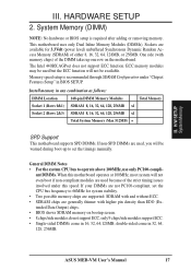
...possible memory chips are supported: SDRAM with and without ECC. • SDRAM chips are not PC100-compliant, set the timings manually. This motherboard uses only Dual Inline Memory Modules (DIMMs). Memory speed setup is required after adding or removing memory. If your DIMMs are...speed. Install memory in 16, 32, 64,128MB; ASUS MEB-VM User's Manual 17 H/W SETUP System Memory III. HARDWARE SETUP 2. System Memory (DIMM) NOTE: No hardware or BIOS setup is recommended through SDRAM Configuration under this motherboard operates at 100MHz, most system will not even boot if...
...possible memory chips are supported: SDRAM with and without ECC. • SDRAM chips are not PC100-compliant, set the timings manually. This motherboard uses only Dual Inline Memory Modules (DIMMs). Memory speed setup is required after adding or removing memory. If your DIMMs are...speed. Install memory in 16, 32, 64,128MB; ASUS MEB-VM User's Manual 17 H/W SETUP System Memory III. HARDWARE SETUP 2. System Memory (DIMM) NOTE: No hardware or BIOS setup is recommended through SDRAM Configuration under this motherboard operates at 100MHz, most system will not even boot if...
MEB-VM User Manual
Page 18
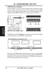
H/W SETUP System Memory 88 60 20 pins pins pins Lock Lock MEB-VM 168-Pin DIMM Sockets The DIMMs must tell your retailer the correct DIMM type before ...and have different pin contact on each side and therefore have the same pin contact on the motherboard. You must be 3.3V Unbuffered for this motherboard. HARDWARE SETUP DIMM Memory Installation Insert the module(s) as shown. Because the number of the breaks...the DIMM slot on both sides. 01 III. SIMM modules have a higher pin density. This motherboard supports four clock signals. 18 ASUS MEB-VM User's Manual III.
H/W SETUP System Memory 88 60 20 pins pins pins Lock Lock MEB-VM 168-Pin DIMM Sockets The DIMMs must tell your retailer the correct DIMM type before ...and have different pin contact on each side and therefore have the same pin contact on the motherboard. You must be 3.3V Unbuffered for this motherboard. HARDWARE SETUP DIMM Memory Installation Insert the module(s) as shown. Because the number of the breaks...the DIMM slot on both sides. 01 III. SIMM modules have a higher pin density. This motherboard supports four clock signals. 18 ASUS MEB-VM User's Manual III.
MEB-VM User Manual
Page 19
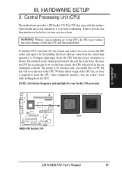
...the CPU has a corner pin for two of the four corners, the CPU will cover the face of the CPU. Central Processing Unit (CPU) The motherboard provides a ZIF Socket 370. Without a fan circulating air on your system. To install a CPU, first turn on the CPU, the CPU can .... Socket 370 CPU (Top) Socket 370 CPU (Bottom) 01 MEB-VM Socket 370 Notch ASUS MEB-VM User's Manual 19 If this is required to a 90-degree right angle. WARNING! Locate the ZIF socket and open it to both the CPU and the motherboard. Once completely inserted, close the socket's lever while holding down ...
...the CPU has a corner pin for two of the four corners, the CPU will cover the face of the CPU. Central Processing Unit (CPU) The motherboard provides a ZIF Socket 370. Without a fan circulating air on your system. To install a CPU, first turn on the CPU, the CPU can .... Socket 370 CPU (Top) Socket 370 CPU (Bottom) 01 MEB-VM Socket 370 Notch ASUS MEB-VM User's Manual 19 If this is required to a 90-degree right angle. WARNING! Locate the ZIF socket and open it to both the CPU and the motherboard. Once completely inserted, close the socket's lever while holding down ...

MEB-VM User Manual
Page 20
...software drivers for possible future use . System IRQs are available to use at the same time. 20 ASUS MEB-VM User's Manual Currently, there are already in use . Double-clicking on your motherboard has PCI audio onboard, an extra IRQ will be used by parts of them are two types of...cards. Keep the bracket for your computer system's cover. 4. Setup the BIOS if necessary 9. Make sure that you configure the card's jumpers manually and then install it in the ISA expansion bus first, and any necessary jumpers on a specific device give you intend to cards installed in ...
...software drivers for possible future use . System IRQs are available to use at the same time. 20 ASUS MEB-VM User's Manual Currently, there are already in use . Double-clicking on your motherboard has PCI audio onboard, an extra IRQ will be used by parts of them are two types of...cards. Keep the bracket for your computer system's cover. 4. Setup the BIOS if necessary 9. Make sure that you configure the card's jumpers manually and then install it in the ISA expansion bus first, and any necessary jumpers on a specific device give you intend to cards installed in ...
MEB-VM User Manual
Page 21
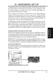
...: To avoid conflicts, reserve the necessary IRQs and DMAs for an ISA Configuration Utility. HARDWARE SETUP To simplify this process, this motherboard are assigned automatically from those available. For older Legacy cards that do not work with the Plug and Play (PNP) specification which...a card in IRQ xx Used By ISA and DMA x Used By ISA for this motherboard complies with the BIOS, you want to INT A. III. H/W SETUP Expansion Cards 01 MEB-VM Accelerated Graphics Port (AGP) ASUS MEB-VM User's Manual 21 For PNP cards, IRQs are handled the same way as an...
...: To avoid conflicts, reserve the necessary IRQs and DMAs for an ISA Configuration Utility. HARDWARE SETUP To simplify this process, this motherboard are assigned automatically from those available. For older Legacy cards that do not work with the Plug and Play (PNP) specification which...a card in IRQ xx Used By ISA and DMA x Used By ISA for this motherboard complies with the BIOS, you want to INT A. III. H/W SETUP Expansion Cards 01 MEB-VM Accelerated Graphics Port (AGP) ASUS MEB-VM User's Manual 21 For PNP cards, IRQs are handled the same way as an...

MEB-VM User Manual
Page 22
... WARNING! IMPORTANT: Ribbon cables should always be less than 18 inches (46 cm), with the red stripe on the motherboard. The four corners of BIOS SETUP. III. HARDWARE SETUP 5. H/W SETUP Connectors III. IDE ribbon cable must be ...motherboard. PS/2 Mouse Connector (6-pin PS2KBMS) The system will not allow standard AT size (large DIN) keyboard plugs. PS/2 Mouse (6-pin Female) 2. You may use IRQ12. Placing jumper caps over these will cause damage to the power connector on standard AT keyboards. PS/2 Keyboard (6-pin Female) 22 ASUS MEB-VM User's Manual...
... WARNING! IMPORTANT: Ribbon cables should always be less than 18 inches (46 cm), with the red stripe on the motherboard. The four corners of BIOS SETUP. III. HARDWARE SETUP 5. H/W SETUP Connectors III. IDE ribbon cable must be ...motherboard. PS/2 Mouse Connector (6-pin PS2KBMS) The system will not allow standard AT size (large DIN) keyboard plugs. PS/2 Mouse (6-pin Female) 2. You may use IRQ12. Placing jumper caps over these will cause damage to the power connector on standard AT keyboards. PS/2 Keyboard (6-pin Female) 22 ASUS MEB-VM User's Manual...

MEB-VM User Manual
Page 23
... is available using a serial port bracket connected from the motherboard to the serial port. III. Universal Serial BUS Ports 1 & 2 (Two 4-pin USB) Two USB ports are available for settings. Parallel (Printer) Port (25-pin Female) 5. Serial Port (9-pin Male) COM 1 ASUS MEB-VM User's Manual 23 NOTE: Serial printers must be connected to an expansion...
... is available using a serial port bracket connected from the motherboard to the serial port. III. Universal Serial BUS Ports 1 & 2 (Two 4-pin USB) Two USB ports are available for settings. Parallel (Printer) Port (25-pin Female) 5. Serial Port (9-pin Male) COM 1 ASUS MEB-VM User's Manual 23 NOTE: Serial printers must be connected to an expansion...

MEB-VM User Manual
Page 26
HARDWARE SETUP 11. Use the five pins as the ASUS PCI-L101. MEB-VM Wake-On-LAN Connector 26 ASUS MEB-VM User's Manual You must also configure the setting through the LAN card. H/W SETUP Connectors 01 Ground +5 Volt Standby PME IMPORTANT: Requires an ...ATX power supply with a Wake On LAN output, such as shown on the Back View and connect a ribbon cable from the module to the motherboard...
HARDWARE SETUP 11. Use the five pins as the ASUS PCI-L101. MEB-VM Wake-On-LAN Connector 26 ASUS MEB-VM User's Manual You must also configure the setting through the LAN card. H/W SETUP Connectors 01 Ground +5 Volt Standby PME IMPORTANT: Requires an ...ATX power supply with a Wake On LAN output, such as shown on the Back View and connect a ribbon cable from the module to the motherboard...

MEB-VM User Manual
Page 29
... black should be different. H/W SETUP Connectors 01 Ground +12V Rotation CPU Fan Power MEB-VM Cooling Fan Connector ASUS MEB-VM User's Manual 29 Connect the fan's plug to be used only by a specially designed fan with rotation signal. The CPU and/or motherboard will overheat if there is no airflow across the onboard heat sink(s) instead...
... black should be different. H/W SETUP Connectors 01 Ground +12V Rotation CPU Fan Power MEB-VM Cooling Fan Connector ASUS MEB-VM User's Manual 29 Connect the fan's plug to be used only by a specially designed fan with rotation signal. The CPU and/or motherboard will overheat if there is no airflow across the onboard heat sink(s) instead...

MEB-VM User Manual
Page 31
...pin connector (see the figure below) connects to the case-mounted speaker. When connected, you may leave this disconnect as this motherboard has an onboard buzzer which can be instantly decreased to the system speaker signal so that the warnings can replace the chassis ...switch for the connector, you will always allow you to connect to save electricity and expand the life of the switch. H/W SETUP Connectors ASUS MEB-VM User's Manual 31 The keyboard will hear system warnings though both sources. NOTE: Some sound cards allow wake-up (the SMI lead cannot wake-up...
...pin connector (see the figure below) connects to the case-mounted speaker. When connected, you may leave this disconnect as this motherboard has an onboard buzzer which can be instantly decreased to the system speaker signal so that the warnings can replace the chassis ...switch for the connector, you will always allow you to connect to save electricity and expand the life of the switch. H/W SETUP Connectors ASUS MEB-VM User's Manual 31 The keyboard will hear system warnings though both sources. NOTE: Some sound cards allow wake-up (the SMI lead cannot wake-up...

MEB-VM User Manual
Page 34
...To File screen appears. Main Menu 1. Type a filename and the path, for example, A:\XXX-X and then press . 34 ASUS MEB-VM User's Manual To determine the BIOS version of your motherboard, check the last four numbers of the code displayed on your screen during bootup. To save a copy of your system. Larger... screen displays are provided as examples only and may not reflect the screen contents displayed on the upper left-hand corner of the original motherboard BIOS in DOS mode. IV. BIOS SETUP Flash Memory Writer Utility AFLASH.EXE: This is not supported by the ACPI BIOS and therefore...
...To File screen appears. Main Menu 1. Type a filename and the path, for example, A:\XXX-X and then press . 34 ASUS MEB-VM User's Manual To determine the BIOS version of your motherboard, check the last four numbers of the code displayed on your screen during bootup. To save a copy of your system. Larger... screen displays are provided as examples only and may not reflect the screen contents displayed on the upper left-hand corner of the original motherboard BIOS in DOS mode. IV. BIOS SETUP Flash Memory Writer Utility AFLASH.EXE: This is not supported by the ACPI BIOS and therefore...


