
User Manual
Page 31
... PANEL) 12. USB910; Power-on switch 15. IEEE 1394a port connector (10-1 pin IE1394_2) 18. DDR2 DIMM slots 5. Clear RTC RAM (3-pin CLRTC_SW) 11. Reset switch 16. ROG connector (2-pin ROG) Page 2-28 2-31 2-8 2-13 2-29 2-23 2-24 2-25...connectors. 2.2.3 Layout contents Connectors/Jumpers/Slots 1. Chassis intrusion connector (4-1 pin CHASSIS) 6. Thermal sensor cable connectors (2-pin OPT_TEMP1-3) 17. ASUS Maximus II Formula 2-5 CPU, chassis, and power fan connectors (4-pin CPU_FAN; 3-pin CHA_FAN1-3; 3-pin PWR_FAN; 3-pin OPT_FAN1-3) 2. SIL5723 Serial ATA ...
... PANEL) 12. USB910; Power-on switch 15. IEEE 1394a port connector (10-1 pin IE1394_2) 18. DDR2 DIMM slots 5. Clear RTC RAM (3-pin CLRTC_SW) 11. Reset switch 16. ROG connector (2-pin ROG) Page 2-28 2-31 2-8 2-13 2-29 2-23 2-24 2-25...connectors. 2.2.3 Layout contents Connectors/Jumpers/Slots 1. Chassis intrusion connector (4-1 pin CHASSIS) 6. Thermal sensor cable connectors (2-pin OPT_TEMP1-3) 17. ASUS Maximus II Formula 2-5 CPU, chassis, and power fan connectors (4-pin CPU_FAN; 3-pin CHA_FAN1-3; 3-pin PWR_FAN; 3-pin OPT_FAN1-3) 2. SIL5723 Serial ATA ...
User Manual
Page 45
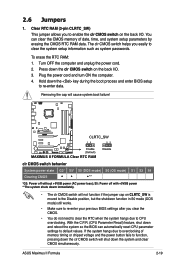
To erase the RTC RAM: 1. Plug the power cord and turn ON the computer. 4. Turn OFF the computer and unplug the power cord. 2. With the C.P.R. (CPU Parameter Recall) feature, shut down the clr CMOS switch on the back I /O. ASUS Maximus II Formula 2-19 Press down and reboot the system so the ...and clear CMOS simultaneously. You can automatically reset CPU parameter settings to clear the system setup information such as system passwords. Clear RTC RAM (3-pin CLRTC_SW) This jumper allows you to enable the clr CMOS switch on CLRTC_SW is moved to the Disable position, but the ...
To erase the RTC RAM: 1. Plug the power cord and turn ON the computer. 4. Turn OFF the computer and unplug the power cord. 2. With the C.P.R. (CPU Parameter Recall) feature, shut down the clr CMOS switch on the back I /O. ASUS Maximus II Formula 2-19 Press down and reboot the system so the ...and clear CMOS simultaneously. You can automatically reset CPU parameter settings to clear the system setup information such as system passwords. Clear RTC RAM (3-pin CLRTC_SW) This jumper allows you to enable the clr CMOS switch on CLRTC_SW is moved to the Disable position, but the ...

User Manual
Page 76
...in this motherboard apply for this utility. The firmware chip on the system chassis. You can change the power management settings. The Setup program is designed to make it lets you scroll through the various sub-menus and make your screen. • Visit the ASUS website (www.asus.com) to... enter the Setup utility; See section 3.9 Exit Menu. • The BIOS setup screens shown in the CMOS RAM of your computer in section 3.1 Managing and updating your BIOS.
...in this motherboard apply for this utility. The firmware chip on the system chassis. You can change the power management settings. The Setup program is designed to make it lets you scroll through the various sub-menus and make your screen. • Visit the ASUS website (www.asus.com) to... enter the Setup utility; See section 3.9 Exit Menu. • The BIOS setup screens shown in the CMOS RAM of your computer in section 3.1 Managing and updating your BIOS.

User Manual
Page 109
..., type a password composed of the screen shows the default Not Installed. ASUS Maximus II Formula 3-41 The message "Password Installed" appears after you can clear it by erasing the CMOS Real Time Clock (RTC) RAM. If you forget your BIOS password, you successfully set a Supervisor Password... UTILITY Boot Supervisor Password User Password :Not Installed :Not Installed Change Supervisor Password Change User Password to erase the RTC RAM. To clear the supervisor password, select the Change Supervisor Password then press . See section 2.6 Jumpers for information on top...
..., type a password composed of the screen shows the default Not Installed. ASUS Maximus II Formula 3-41 The message "Password Installed" appears after you can clear it by erasing the CMOS Real Time Clock (RTC) RAM. If you forget your BIOS password, you successfully set a Supervisor Password... UTILITY Boot Supervisor Password User Password :Not Installed :Not Installed Change Supervisor Password Change User Password to erase the RTC RAM. To clear the supervisor password, select the Change Supervisor Password then press . See section 2.6 Jumpers for information on top...
User Manual
Page 114
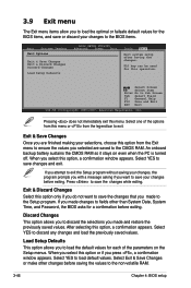
... Go to save the changes that you to load the optimal or failsafe default values for a confirmation before saving the values to the non-volatile RAM. 3-46 Chapter 4: BIOS setup Pressing does not immediately exit this option, a confirmation appears. Select one of the parameters on even when the PC ... changes to fields other changes before exiting. Discard Changes This option allows you to discard the selections you selected are saved to the CMOS RAM. When you select this menu or from the Exit menu to ensure the values you made and restore the previously saved values. If you...
... Go to save the changes that you to load the optimal or failsafe default values for a confirmation before saving the values to the non-volatile RAM. 3-46 Chapter 4: BIOS setup Pressing does not immediately exit this option, a confirmation appears. Select one of the parameters on even when the PC ... changes to fields other changes before exiting. Discard Changes This option allows you to discard the selections you selected are saved to the CMOS RAM. When you select this menu or from the Exit menu to ensure the values you made and restore the previously saved values. If you...
User Manual
Page 172
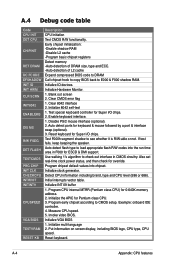
...Enable keyboard interface. 1. Auto detect flash type to load appropriate flash R/W codes into chipset. Program early chipset according to E000 & F000 shadow RAM. Put information on screen display, including BIOS logo, CPU type, CPU speed . Reset keyboard. Initialize INT 09 buffer 1. Initialize VGA BIOS ...default values into the run time area in CMOS circuitry. Example: onboard IDE controller. 4. Early chipset initialization: -Disable shadow RAM -Disable L2 cache -Program basic chipset registers Detect memory -Auto-detection of DRAM size, type and ECC. -Auto-detection ...
...Enable keyboard interface. 1. Auto detect flash type to load appropriate flash R/W codes into chipset. Program early chipset according to E000 & F000 shadow RAM. Put information on screen display, including BIOS logo, CPU type, CPU speed . Reset keyboard. Initialize INT 09 buffer 1. Initialize VGA BIOS ...default values into the run time area in CMOS circuitry. Example: onboard IDE controller. 4. Early chipset initialization: -Disable shadow RAM -Disable L2 cache -Program basic chipset registers Detect memory -Auto-detection of DRAM size, type and ECC. -Auto-detection ...


