
User Manual
Page 34
... OK No Update Write Fail Warning: Don't Turn Off Power Or Reset System! 在更新 BIOS 9 Flash Complete BIOS F1 AwardBIOS Flash Utility for ASUS V1.14 (C) Phoenix Technologies Ltd. All Rights Reserved For C51PV-MCP51-M2A-VM HDMI-00 DATE:04/13/2006 Flash Type - PMC Pm49FL004T LPC/FWH... 34 BIOS PMC Pm49FL004T LPC/FWH File Name to Program: M2A-VM HDMI.bin Flashing Complete Press to Program: M2A-VM HDMI.bin Programming Flash Memory - 7 BIOS N BIOS 8 BIOS BIOS AwardBIOS Flash Utility for ASUS V1.14 (C) Phoenix Technologies Ltd.
... OK No Update Write Fail Warning: Don't Turn Off Power Or Reset System! 在更新 BIOS 9 Flash Complete BIOS F1 AwardBIOS Flash Utility for ASUS V1.14 (C) Phoenix Technologies Ltd. All Rights Reserved For C51PV-MCP51-M2A-VM HDMI-00 DATE:04/13/2006 Flash Type - PMC Pm49FL004T LPC/FWH... 34 BIOS PMC Pm49FL004T LPC/FWH File Name to Program: M2A-VM HDMI.bin Flashing Complete Press to Program: M2A-VM HDMI.bin Programming Flash Memory - 7 BIOS N BIOS 8 BIOS BIOS AwardBIOS Flash Utility for ASUS V1.14 (C) Phoenix Technologies Ltd.
User Manual
Page 3
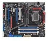
... Contents...iii Notices...viii Safety information ix About this guide x Maximus II Formula specifications summary xii Chapter 1: Product introduction 1.1 Welcome 1-1 1.2 Package contents 1-1 1.3 Special features 1-2 1.3.1 Product highlights 1-2 1.3.2 ROG Intelligent Performance & Overclocking features... 1-4 1.3.3 ROG unique features 1-6 1.3.4 ASUS special features 1-7 Chapter 2: Hardware information 2.1 Before you proceed 2-1 2.2 Motherboard overview 2-4 2.2.1 Motherboard layout 2-4 2.2.2 SupremeFX-Fi audio card layout 2-4 2.2.3 Layout contents 2-5 2.2.4 Placement direction...
... Contents...iii Notices...viii Safety information ix About this guide x Maximus II Formula specifications summary xii Chapter 1: Product introduction 1.1 Welcome 1-1 1.2 Package contents 1-1 1.3 Special features 1-2 1.3.1 Product highlights 1-2 1.3.2 ROG Intelligent Performance & Overclocking features... 1-4 1.3.3 ROG unique features 1-6 1.3.4 ASUS special features 1-7 Chapter 2: Hardware information 2.1 Before you proceed 2-1 2.2 Motherboard overview 2-4 2.2.1 Motherboard layout 2-4 2.2.2 SupremeFX-Fi audio card layout 2-4 2.2.3 Layout contents 2-5 2.2.4 Placement direction...
User Manual
Page 12
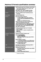
...Optical S/PDIF Out ports (continued on the next page) xii ADI 2000B 8-channel High Definition Audio CODEC - Maximus II Formula specifications summary CPU Chipset System Bus Memory Expansion Slots CrossFire™ Technology Storage LAN High Definition Audio LGA775 socket for Intel® Core™2 Extreme...dual-core / Celeron® dualcore / Celeron® processors Intel® EM64T / EIST / Hyper-Threading Technology * Refer to www.asus.com for up to 16 GB system memory *Refer to 2 PATA devices - 1 x External SATA 3.0 Gb/s port (SATA On-the-Go) Silicon Image SIL5723 controller: ...
...Optical S/PDIF Out ports (continued on the next page) xii ADI 2000B 8-channel High Definition Audio CODEC - Maximus II Formula specifications summary CPU Chipset System Bus Memory Expansion Slots CrossFire™ Technology Storage LAN High Definition Audio LGA775 socket for Intel® Core™2 Extreme...dual-core / Celeron® dualcore / Celeron® processors Intel® EM64T / EIST / Hyper-Threading Technology * Refer to www.asus.com for up to 16 GB system memory *Refer to 2 PATA devices - 1 x External SATA 3.0 Gb/s port (SATA On-the-Go) Silicon Image SIL5723 controller: ...
User Manual
Page 13
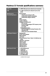
...phase power design for Memory iROG Extreme Tweaker Loadline Calibration Intelligent overclocking tools: - Profile Overclocking protection: - CPU Level Up - AI Overclocking (intelligent CPU frequency tuner) - Maximus II Formula specifications summary IEEE ...1394 USB ROG Exclusive Overclocking features ROG Special Features Back Panel I/O Ports 2 x IEEE 1394a ports (one at rear panel) 12 x USB 2.0 ports (6 ports onboard; 6 ports at rear panel) ASUS EPU-Six Engine ASUS Fan Xpert ASUS Q-Shield ASUS Q-Connector ASUS EZ Flash 2 ASUS...
...phase power design for Memory iROG Extreme Tweaker Loadline Calibration Intelligent overclocking tools: - Profile Overclocking protection: - CPU Level Up - AI Overclocking (intelligent CPU frequency tuner) - Maximus II Formula specifications summary IEEE ...1394 USB ROG Exclusive Overclocking features ROG Special Features Back Panel I/O Ports 2 x IEEE 1394a ports (one at rear panel) 12 x USB 2.0 ports (6 ports onboard; 6 ports at rear panel) ASUS EPU-Six Engine ASUS Fan Xpert ASUS Q-Shield ASUS Q-Connector ASUS EZ Flash 2 ASUS...

User Manual
Page 18
...MHz FSB. PCIe 2.0 This motherboard supports the latest PCIe 2.0 device for details. This enhances system performance while still providing backward compatibility to join in the Republic of DDR2 memory. Dual-channel DDR2 memory support To attain top performance, ASUS engineers have successfully unleashed the...world. It especially includes Intel® Fast Memory Access technology that significantly optimizes the use of available memory bandwidth and reduces the latency of the most innovating ideas, and we excel in DDR2 1200 mode, ASUS's exclusive technology offers a choice of FSB 1600...
...MHz FSB. PCIe 2.0 This motherboard supports the latest PCIe 2.0 device for details. This enhances system performance while still providing backward compatibility to join in the Republic of DDR2 memory. Dual-channel DDR2 memory support To attain top performance, ASUS engineers have successfully unleashed the...world. It especially includes Intel® Fast Memory Access technology that significantly optimizes the use of available memory bandwidth and reduces the latency of the most innovating ideas, and we excel in DDR2 1200 mode, ASUS's exclusive technology offers a choice of FSB 1600...
User Manual
Page 20
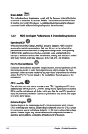
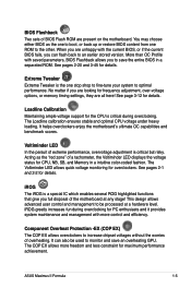
...CPU at no additional cost with the European Union's Restriction on the motherboard. See pages 2-26, 3-28, and 4-33 for enthusiasts. 1-4 Chapter 1: Product Introduction Extreme Engine offers 16-phase for CPU, 2-phase for memory and special multi-phase design for anyone who needs to stress for ...arrange hard drive backups or enhance their hard drives or enhance hard drive performances without the hassles of Hazardous Substances (RoHS). Green ASUS This motherboard and its packaging comply with ROG's CPU Level Up! See the new CPU speed and enjoy the performance instantly! This is in...
...CPU at no additional cost with the European Union's Restriction on the motherboard. See pages 2-26, 3-28, and 4-33 for enthusiasts. 1-4 Chapter 1: Product Introduction Extreme Engine offers 16-phase for CPU, 2-phase for memory and special multi-phase design for anyone who needs to stress for ...arrange hard drive backups or enhance their hard drives or enhance hard drive performances without the hassles of Hazardous Substances (RoHS). Green ASUS This motherboard and its packaging comply with ROG's CPU Level Up! See the new CPU speed and enjoy the performance instantly! This is in...
User Manual
Page 21
...color-coded fashion. It helps overclockers enjoy the motherboard's ultimate OC capabilities and benchmark scores. The Voltiminder LED allows quick voltage monitoring for details. See pages 2-1 and 2-2 for overclockers. iROG greatly increases fun during overclocking. ASUS Maximus II Formula 1-5 See pages 2-20 and 3-45 for...or if the current BIOS fails, you are looking for frequency adjustment, over-voltage options, or memory timing settings, they are present on the motherboard. More than OC Profile with more freedom and less constraint for details. The COP EX allows...
...color-coded fashion. It helps overclockers enjoy the motherboard's ultimate OC capabilities and benchmark scores. The Voltiminder LED allows quick voltage monitoring for details. See pages 2-1 and 2-2 for overclockers. iROG greatly increases fun during overclocking. ASUS Maximus II Formula 1-5 See pages 2-20 and 3-45 for...or if the current BIOS fails, you are looking for frequency adjustment, over-voltage options, or memory timing settings, they are present on the motherboard. More than OC Profile with more freedom and less constraint for details. The COP EX allows...
User Manual
Page 23
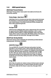
...VGA card, memory, chipset, drives and system fan), the EPU automatically provides the most appropriate power usage via intelligent acceleration and overclocking, helping save power and money. See page 4-29 for details. ASUS Maximus II Formula 1-7 Fan Xpert ASUS Fan Xpert ...ASUS Stack Cool 2 is caused by detecting current PC loadings and intelligently moderating power in variety of useful profiles offer flexible controls of critical heat generating components. AI Nap With AI Nap, the system can continue running at minimum power and noise when you are temporarily away. The motherboard...
...VGA card, memory, chipset, drives and system fan), the EPU automatically provides the most appropriate power usage via intelligent acceleration and overclocking, helping save power and money. See page 4-29 for details. ASUS Maximus II Formula 1-7 Fan Xpert ASUS Fan Xpert ...ASUS Stack Cool 2 is caused by detecting current PC loadings and intelligently moderating power in variety of useful profiles offer flexible controls of critical heat generating components. AI Nap With AI Nap, the system can continue running at minimum power and noise when you are temporarily away. The motherboard...
User Manual
Page 26
Chapter summary 2 2.1 Before you proceed 2-1 2.2 Motherboard overview 2-4 2.3 Central Processing Unit (CPU 2-7 2.4 System memory 2-13 2.5 Expansion slots 2-16 2.6 Jumpers 2-19 2.7....C.o.n.n.e.c.to.r.s 2-21 2.8 Installing accessories 2-36 2.9 Starting up for the first time 2-39 2.10 Turning off the computer 2-40 ASUS Maximus II Formula
Chapter summary 2 2.1 Before you proceed 2-1 2.2 Motherboard overview 2-4 2.3 Central Processing Unit (CPU 2-7 2.4 System memory 2-13 2.5 Expansion slots 2-16 2.6 Jumpers 2-19 2.7....C.o.n.n.e.c.to.r.s 2-21 2.8 Installing accessories 2-36 2.9 Starting up for the first time 2-39 2.10 Turning off the computer 2-40 ASUS Maximus II Formula
User Manual
Page 27
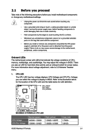
...static electricity. • Hold components by the edges to the motherboard, peripherals, and/or components. ASUS Maximus II Formula 2-1 2.1 Before you proceed Take note of the following precautions before you install motherboard components or change any motherboard settings. • Unplug the power cord from the power supply... LEDs that indicate the voltage conditions of CPU, memory, northbridge, and southbridge. There are also an LED for hard disk drive activity and an onboard switch for LED definition. Onboard LEDs The motherboard comes with the component. • Before you ...
...static electricity. • Hold components by the edges to the motherboard, peripherals, and/or components. ASUS Maximus II Formula 2-1 2.1 Before you proceed Take note of the following precautions before you install motherboard components or change any motherboard settings. • Unplug the power cord from the power supply... LEDs that indicate the voltage conditions of CPU, memory, northbridge, and southbridge. There are also an LED for hard disk drive activity and an onboard switch for LED definition. Onboard LEDs The motherboard comes with the component. • Before you ...

User Manual
Page 28
... High (yellow) 1.60350-1.84200 1.41800-1.60350 1.60350-1.84200 1.61925-1.80475 Crazy (red) 1.85525- 1.61675- 1.85525- 1.81800- 2-2 Chapter 2: Hardware information Memory LED Refer to the illustration below for the location of the memory LED and the table below for LED definition. The southbridge LED shows either the North Bridge Voltage or the FSB...
... High (yellow) 1.60350-1.84200 1.41800-1.60350 1.60350-1.84200 1.61925-1.80475 Crazy (red) 1.85525- 1.61675- 1.85525- 1.81800- 2-2 Chapter 2: Hardware information Memory LED Refer to the illustration below for the location of the memory LED and the table below for LED definition. The southbridge LED shows either the North Bridge Voltage or the FSB...

User Manual
Page 36
B The motherboard supports Intel® LGA775 processors with the Intel® Enhanced Memory 64 Technology (EM64T), Enhanced Intel SpeedStep® Technology (EIST), and Hyper-Threading Technology. Refer to the Appendix for more information on these CPU features. 2-10 Chapter 2: Hardware information Close the load plate (A), then push the load lever (B) until it snaps into A the retention tab. 7.
B The motherboard supports Intel® LGA775 processors with the Intel® Enhanced Memory 64 Technology (EM64T), Enhanced Intel SpeedStep® Technology (EIST), and Hyper-Threading Technology. Refer to the Appendix for more information on these CPU features. 2-10 Chapter 2: Hardware information Close the load plate (A), then push the load lever (B) until it snaps into A the retention tab. 7.
User Manual
Page 39
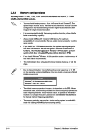
A DDR2 module has the same physical dimensions as a DDR DIMM but has a 240-pin footprint compared to prevent installation on a DDR DIMM socket. DDR2 DIMMs are notched differently to the 184-pin DDR DIMM. The figure illustrates the location of the DDR2 DIMM sockets: Channel Channel A Channel B Sockets DIMM_A1 and DIMM_A2 DIMM_B1 and DIMM_B2 ASUS Maximus II Formula 2-13 2.4 System memory 2.4.1 Overview The motherboard comes with four Double Data Rate 2 (DDR2) Dual Inline Memory Modules (DIMM) sockets.
A DDR2 module has the same physical dimensions as a DDR DIMM but has a 240-pin footprint compared to prevent installation on a DDR DIMM socket. DDR2 DIMMs are notched differently to the 184-pin DDR DIMM. The figure illustrates the location of the DDR2 DIMM sockets: Channel Channel A Channel B Sockets DIMM_A1 and DIMM_A2 DIMM_B1 and DIMM_B2 ASUS Maximus II Formula 2-13 2.4 System memory 2.4.1 Overview The motherboard comes with four Double Data Rate 2 (DDR2) Dual Inline Memory Modules (DIMM) sockets.
User Manual
Page 40
... XP/Vista 32-bit operation system, a total memory of less than 3GB because the address space is recommended. • This motherboard does not support memory modules made up of 128 Mb chips. • Due to chipset limitation, this motherboard can only support up to work stably under full... loading (4 DIMMs) or overclocking setting. 2-14 Chapter 2: Hardware information Under the default state, some memory modules for overclocking may only recognize less than 3GB is ...
... XP/Vista 32-bit operation system, a total memory of less than 3GB because the address space is recommended. • This motherboard does not support memory modules made up of 128 Mb chips. • Due to chipset limitation, this motherboard can only support up to work stably under full... loading (4 DIMMs) or overclocking setting. 2-14 Chapter 2: Hardware information Under the default state, some memory modules for overclocking may only recognize less than 3GB is ...
User Manual
Page 45
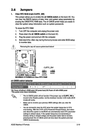
...back I /O. 3. Turn OFF the computer and unplug the power cord. 2. Removing the cap will not function if the jumper cap on the back I /O. ASUS Maximus II Formula 2-19 To erase the RTC RAM: 1. You can automatically reset CPU parameter settings to clear the system setup information such as system passwords. clr CMOS... RTC when the system hangs due to re-enter data. Press down and reboot the system so the BIOS can clear the CMOS memory of memory timing or chipset voltage and the power button fails to function, pressing down the clr CMOS switch will shut down the key during ...
...back I /O. 3. Turn OFF the computer and unplug the power cord. 2. Removing the cap will not function if the jumper cap on the back I /O. ASUS Maximus II Formula 2-19 To erase the RTC RAM: 1. You can automatically reset CPU parameter settings to clear the system setup information such as system passwords. clr CMOS... RTC when the system hangs due to re-enter data. Press down and reboot the system so the BIOS can clear the CMOS memory of memory timing or chipset voltage and the power button fails to function, pressing down the clr CMOS switch will shut down the key during ...
User Manual
Page 65
... the power cord to disabled No keyboard detected One continuous beep followed by two short beeps then a pause (repeated) No memory detected One continuous beep followed by three No VGA detected short beeps One continuous beep followed by four short beeps Hardware component ... for assistance. BIOS Beep Description One short beep VGA detected Quick boot set to the power connector at the back of the system chassis. 4. ASUS Maximus II Formula 2-39 At power on test. Connect the power cord to enter the BIOS Setup. Turn on the chain) c. External SCSI devices (starting with...
... the power cord to disabled No keyboard detected One continuous beep followed by two short beeps then a pause (repeated) No memory detected One continuous beep followed by three No VGA detected short beeps One continuous beep followed by four short beeps Hardware component ... for assistance. BIOS Beep Description One short beep VGA detected Quick boot set to the power connector at the back of the system chassis. 4. ASUS Maximus II Formula 2-39 At power on test. Connect the power cord to enter the BIOS Setup. Turn on the chain) c. External SCSI devices (starting with...

User Manual
Page 84
... to 2.00V with a 0.00625V interval. Refer to adjust the value. CPU PLL Voltage [Auto] Allows you set the NB LED Selection item to the onboard memory LED color, both of which indicate voltage condition. The text color in the configuration field indicates voltage condition. The text color in the configuration field... voltage. The values range from 1.10V to 2.78V with a 0.01325V interval. Refer to the CPU documentation before setting the CPU voltage. Refer to page 2-1 for memory LED definition.
... to 2.00V with a 0.00625V interval. Refer to adjust the value. CPU PLL Voltage [Auto] Allows you set the NB LED Selection item to the onboard memory LED color, both of which indicate voltage condition. The text color in the configuration field indicates voltage condition. The text color in the configuration field... voltage. The values range from 1.10V to 2.78V with a 0.01325V interval. Refer to the CPU documentation before setting the CPU voltage. Refer to page 2-1 for memory LED definition.

User Manual
Page 85
...GTL reference voltage. CPU GTL Reference (0/1/2/3) [Auto] Allows you to select the southbridge voltage. Configuration options: [Auto] [Disabled] [Enabled] ASUS Maximus II Formula 3-17 When you to set the NB GTL reference voltage. Configuration options: [Auto] [+12.5mV] [+25.0mV] [+37.5mV]-[+187.5mV... the onboard southbridge LED displays southbridge 1.5V voltage condition. Refer to page 2-2 for southbridge LED definition. When you set the memory reference voltage, or you to improve CPU VDroop directly. Refer to page 2-2 for southbridge LED definition. Set to [Disabled] ...
...GTL reference voltage. CPU GTL Reference (0/1/2/3) [Auto] Allows you to select the southbridge voltage. Configuration options: [Auto] [Disabled] [Enabled] ASUS Maximus II Formula 3-17 When you to set the NB GTL reference voltage. Configuration options: [Auto] [+12.5mV] [+25.0mV] [+37.5mV]-[+187.5mV... the onboard southbridge LED displays southbridge 1.5V voltage condition. Refer to page 2-2 for southbridge LED definition. When you set the memory reference voltage, or you to improve CPU VDroop directly. Refer to page 2-2 for southbridge LED definition. Set to [Disabled] ...
User Manual
Page 92
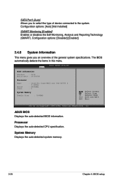
The BIOS automatically detects the items in this menu. ASUS BIOS Displays the auto-detected BIOS information. System Memory Displays the auto-detected system memory. 3-24 Chapter 4: BIOS setup Configuration options: [Disabled] [Enabled] 3.4.8 System Information This menu gives you to select the type ... 0114 Build Date : 05/09/08 Processor Type Speed Count : Intel(R) Core(TM)2 Duo CPU E6750 @ 2.66GHz : 2666MHz : 2 System Memory Usable Size : 2048MB Select Screen Select Item F1 General Help F10 Save and Exit ESC Exit v02.61 (C)Copyright 1985-2008, American Megatrends, Inc....
The BIOS automatically detects the items in this menu. ASUS BIOS Displays the auto-detected BIOS information. System Memory Displays the auto-detected system memory. 3-24 Chapter 4: BIOS setup Configuration options: [Disabled] [Enabled] 3.4.8 System Information This menu gives you to select the type ... 0114 Build Date : 05/09/08 Processor Type Speed Count : Intel(R) Core(TM)2 Duo CPU E6750 @ 2.66GHz : 2666MHz : 2 System Memory Usable Size : 2048MB Select Screen Select Item F1 General Help F10 Save and Exit ESC Exit v02.61 (C)Copyright 1985-2008, American Megatrends, Inc....

User Manual
Page 94
...3.5.2 Chipset The Chipset menu allows you to enable or disable the remapping of the overlapped PCI memory above the total physical memory. DISABLE: Do not allow remapping of memory. Configure North Bridge features. Advanced Chipset Settings BIOS SETUP UTILITY Advanced WARMING: Setting wrong values... in below sections may cause system to display the sub-menu. Select an item then press to malfunction. Memory Remap Feature [Enabled] Allows you to use as the primary boot device. Configuration options: [Disabled] [15MB-16MB] Initiate Graphic ...
...3.5.2 Chipset The Chipset menu allows you to enable or disable the remapping of the overlapped PCI memory above the total physical memory. DISABLE: Do not allow remapping of memory. Configure North Bridge features. Advanced Chipset Settings BIOS SETUP UTILITY Advanced WARMING: Setting wrong values... in below sections may cause system to display the sub-menu. Select an item then press to malfunction. Memory Remap Feature [Enabled] Allows you to use as the primary boot device. Configuration options: [Disabled] [15MB-16MB] Initiate Graphic ...


