
User Manual
Page 1
Motherboard M5A78L-M Series • M5A78L-M LE • M5A78L-M PLUS
Motherboard M5A78L-M Series • M5A78L-M LE • M5A78L-M PLUS
User Manual
Page 11
...power consumption. The layout illustrations in the new 32nm manufacturing process. Before you for M5A78L-M LE only. • If any of ASUS quality motherboards! It features dual-channel DDR3 memory support and accelerates data transfer rate up... items. Motherboard Cables Accessories Application DVD Documentation ASUS M5A78L-M Series motherboard 2 x Serial ATA 3Gb/s cables 1 x I/O shield ASUS motherboard Support DVD User Manual • M5A78L-M Series motherboards include M5A78L-M PLUS and M5A78L-M LE two models. ASUS M5A78L-M Series 1-1 The package contents vary from models...
...power consumption. The layout illustrations in the new 32nm manufacturing process. Before you for M5A78L-M LE only. • If any of ASUS quality motherboards! It features dual-channel DDR3 memory support and accelerates data transfer rate up... items. Motherboard Cables Accessories Application DVD Documentation ASUS M5A78L-M Series motherboard 2 x Serial ATA 3Gb/s cables 1 x I/O shield ASUS motherboard Support DVD User Manual • M5A78L-M Series motherboards include M5A78L-M PLUS and M5A78L-M LE two models. ASUS M5A78L-M Series 1-1 The package contents vary from models...
User Manual
Page 15
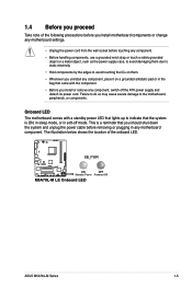
... soft-off the ATX power supply and detach its power cord. 1.4 Before you proceed Take note of the onboard LED. SB_PWR M5A78L-M LE ON OFF Standby Power Powered Off M5A78L-M LE Onboard LED ASUS M5A78L-M Series 1-5 Onboard LED The motherboard comes with the component. • Before you install or remove any motherboard component. Failure to do...
... soft-off the ATX power supply and detach its power cord. 1.4 Before you proceed Take note of the onboard LED. SB_PWR M5A78L-M LE ON OFF Standby Power Powered Off M5A78L-M LE Onboard LED ASUS M5A78L-M Series 1-5 Onboard LED The motherboard comes with the component. • Before you install or remove any motherboard component. Failure to do...

User Manual
Page 16
DO NOT overtighten the screws! Place this side towards the rear of the chassis as indicated in the image below. 1.5.2 Screw holes Place six screws into the chassis in the correct orientation. Doing so can damage the motherboard. The edge with external ports goes to the rear part of the chassis. 1.5 Motherboard overview 1.5.1 Placement direction When installing the motherboard, ensure that you place it into the holes indicated by circles to secure the motherboard to the chassis. M5A78L-M LE 1-6 Chapter 1: Product introduction
DO NOT overtighten the screws! Place this side towards the rear of the chassis as indicated in the image below. 1.5.2 Screw holes Place six screws into the chassis in the correct orientation. Doing so can damage the motherboard. The edge with external ports goes to the rear part of the chassis. 1.5 Motherboard overview 1.5.1 Placement direction When installing the motherboard, ensure that you place it into the holes indicated by circles to secure the motherboard to the chassis. M5A78L-M LE 1-6 Chapter 1: Product introduction
User Manual
Page 18
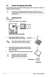
otherwise, the CPU will not fit in one correct orientation. DO NOT force the CPU into the socket to a 90°-100° angle. M5A78L-M LE M5A78L-M LE CPU socket AM3+ 2. Press the lever sideways to unlock the socket, then lift it fits in only one correct orientation. The CPU fits only in ...
otherwise, the CPU will not fit in one correct orientation. DO NOT force the CPU into the socket to a 90°-100° angle. M5A78L-M LE M5A78L-M LE CPU socket AM3+ 2. Press the lever sideways to unlock the socket, then lift it fits in only one correct orientation. The CPU fits only in ...
User Manual
Page 19
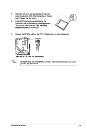
... that it is in place, push down the socket lever to plug this connector. You can occur if you fail to secure the CPU. CPU_FAN M5A78L-M LE M5A78L-M LE CPU fan connector DO NOT forget to the CPU_FAN connector on the side tab to section 1.6.2 Installing heatsink and fan for instructions. 7. 5. Hardware monitoring errors... the CPU is locked. 6. Connect the CPU fan cable to connect the CPU fan connector! CPU FAN PWM CPU FAN IN CPU FAN PWR GND ASUS M5A78L-M Series 1-9 The lever clicks on the motherboard.
... that it is in place, push down the socket lever to plug this connector. You can occur if you fail to secure the CPU. CPU_FAN M5A78L-M LE M5A78L-M LE CPU fan connector DO NOT forget to the CPU_FAN connector on the side tab to section 1.6.2 Installing heatsink and fan for instructions. 7. 5. Hardware monitoring errors... the CPU is locked. 6. Connect the CPU fan cable to connect the CPU fan connector! CPU FAN PWM CPU FAN IN CPU FAN PWR GND ASUS M5A78L-M Series 1-9 The lever clicks on the motherboard.
User Manual
Page 21
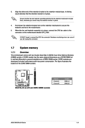
Align the other end of the DDR3 DIMM sockets: DIMM_A1 DIMM_B1 M5A78L-M LE M5A78L-M LE 240-pin DDR3 DIMM sockets Channel Channel A Channel B Sockets DIMM_A1 DIMM_B1 ASUS M5A78L-M Series 1-11 Ensure that the retention bracket is in place. 4. The figure illustrates the location of the retention bracket to connect the CPU fan connector! ...
Align the other end of the DDR3 DIMM sockets: DIMM_A1 DIMM_B1 M5A78L-M LE M5A78L-M LE 240-pin DDR3 DIMM sockets Channel Channel A Channel B Sockets DIMM_A1 DIMM_B1 ASUS M5A78L-M Series 1-11 Ensure that the retention bracket is in place. 4. The figure illustrates the location of the retention bracket to connect the CPU fan connector! ...

User Manual
Page 28
... the jumper again to overclocking, use the CPU Parameter Recall (C.P.R) feature. Plug the power cord and turn ON the computer. 4. CLRTC 12 23 M5A78L-M LE Normal (Default) Clear RTC M5A78L-M LE Clear RTC RAM To erase the RTC RAM: 1. Move the jumper cap from pins 1-2 (default) to pins 1-2. 3. Keep the cap on CLRTC jumper...
... the jumper again to overclocking, use the CPU Parameter Recall (C.P.R) feature. Plug the power cord and turn ON the computer. 4. CLRTC 12 23 M5A78L-M LE Normal (Default) Clear RTC M5A78L-M LE Clear RTC RAM To erase the RTC RAM: 1. Move the jumper cap from pins 1-2 (default) to pins 1-2. 3. Keep the cap on CLRTC jumper...
User Manual
Page 29
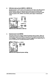
KBPWR 12 23 +5V +5VSB (Default) M5A78L-M LE M5A78L-M LE Keyboard power setting ASUS M5A78L-M Series 1-19 Set these jumpers to +5V to wake up the computer from S3 and S4 sleep modes (no power to wake up feature. USBPW1-4 12 23 +5V +5VSB (Default) USBPW5-12 M5A78L-M LE 12 23 +5V +5VSB (Default) M5A78L-M LE USB device wake-up the...
KBPWR 12 23 +5V +5VSB (Default) M5A78L-M LE M5A78L-M LE Keyboard power setting ASUS M5A78L-M Series 1-19 Set these jumpers to +5V to wake up the computer from S3 and S4 sleep modes (no power to wake up feature. USBPW1-4 12 23 +5V +5VSB (Default) USBPW5-12 M5A78L-M LE 12 23 +5V +5VSB (Default) M5A78L-M LE USB device wake-up the...
User Manual
Page 31
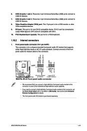
... for a PS/2 keyboard. 1.10.2 Internal connectors 1. See section 2.4.4 Onboard Devices Configuration for a VGA monitor or other VGA-compatible devices. 9. ASUS M5A78L-M Series 1-21 This port is for details. • The front panel audio I /O module that you want to connect a high definition front... 1 MIC2 MICPWR Line out_R NC Line out_L PORT1 L PORT1 R PORT2 R SENSE_SEND PORT2 L M5A78L-M LE HD-audio-compliant Legacy AC'97 pin definition compliant definition M5A78L-M LE Front panel audio connector • We recommend that supports either High Definition Audio or AC`97 audio...
... for a PS/2 keyboard. 1.10.2 Internal connectors 1. See section 2.4.4 Onboard Devices Configuration for a VGA monitor or other VGA-compatible devices. 9. ASUS M5A78L-M Series 1-21 This port is for details. • The front panel audio I /O module that you want to connect a high definition front... 1 MIC2 MICPWR Line out_R NC Line out_L PORT1 L PORT1 R PORT2 R SENSE_SEND PORT2 L M5A78L-M LE HD-audio-compliant Legacy AC'97 pin definition compliant definition M5A78L-M LE Front panel audio connector • We recommend that supports either High Definition Audio or AC`97 audio...
User Manual
Page 32
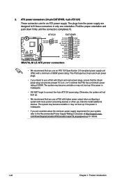
...Power OK GND +5 Volts GND +5 Volts GND +3 Volts +3 Volts PIN 1 GND +5 Volts +5 Volts +5 Volts -5 Volts GND GND GND PSON# GND -12 Volts +3 Volts M5A78L-M LE ATX power connectors • We recommend that the PSU has a minimum power rating of 300W power rating. Otherwise, the system will not boot up. •...compliant power supply unit (PSU) with 20-pin and 4-pin power plugs, ensure that the 20-pin power plug can provide at http://support.asus. The system may become unstable or may not boot up if the power is inadequate. • If you are uncertain about the minimum power...
...Power OK GND +5 Volts GND +5 Volts GND +3 Volts +3 Volts PIN 1 GND +5 Volts +5 Volts +5 Volts -5 Volts GND GND GND PSON# GND -12 Volts +3 Volts M5A78L-M LE ATX power connectors • We recommend that the PSU has a minimum power rating of 300W power rating. Otherwise, the system will not boot up. •...compliant power supply unit (PSU) with 20-pin and 4-pin power plugs, ensure that the 20-pin power plug can provide at http://support.asus. The system may become unstable or may not boot up if the power is inadequate. • If you are uncertain about the minimum power...
User Manual
Page 33
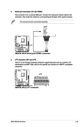
...The serial port bracket is for a serial (COM) port. LPT M5A78L-M LE M5A78L-M LE LPT connector AFD ERR# INIT# SLIN# GND GND GND GND GND GND GND GND PIN 1 STB# PD0 PD1 PD2 PD3 PD4 PD5 PD6 PD7 ACK# BUSY PE SLCT ASUS M5A78L-M Series 1-23 Connect the serial port module cable to the connector..., then install the module to a slot opening at the back of the system chassis. COM1 PIN 1 M5A78L-M LE M5A78L-M LE Serial port (COM1) connector 4. 3.
...The serial port bracket is for a serial (COM) port. LPT M5A78L-M LE M5A78L-M LE LPT connector AFD ERR# INIT# SLIN# GND GND GND GND GND GND GND GND PIN 1 STB# PD0 PD1 PD2 PD3 PD4 PD5 PD6 PD7 ACK# BUSY PE SLCT ASUS M5A78L-M Series 1-23 Connect the serial port module cable to the connector..., then install the module to a slot opening at the back of the system chassis. COM1 PIN 1 M5A78L-M LE M5A78L-M LE Serial port (COM1) connector 4. 3.

User Manual
Page 34
... [RAID] in the support DVD. SATA3G_5 GND RSATA_TXP5 RSATA_TXN5 GND RSATA_RXP5 RSATA_RXN5 GND SATA3G_6 GND RSATA_TXP6 RSATA_TXN6 GND RSATA_RXP6 RSATA_RXN6 GND SATA3G_2 SATA3G_4 SATA3G_1 SATA3G_3 M5A78L-M LE M5A78L-M LE SATA 3.0Gb/s connectors • Install the Windows® XP Service Pack 3 or later versions before using Serial ATA. • If you can create a RAID 0, RAID...
... [RAID] in the support DVD. SATA3G_5 GND RSATA_TXP5 RSATA_TXN5 GND RSATA_RXP5 RSATA_RXN5 GND SATA3G_6 GND RSATA_TXP6 RSATA_TXN6 GND RSATA_RXP6 RSATA_RXN6 GND SATA3G_2 SATA3G_4 SATA3G_1 SATA3G_3 M5A78L-M LE M5A78L-M LE SATA 3.0Gb/s connectors • Install the Windows® XP Service Pack 3 or later versions before using Serial ATA. • If you can create a RAID 0, RAID...

User Manual
Page 35
... lights up when you to this connector. F_PANEL PLED PWRBTN PIN 1 M5A78L-M LE +HDLED RESET M5A78L-M LE System panel connector • System power LED (2-pin PLED) This 2-pin connector is for the HDD Activity LED. SPEAKER M5A78L-M LE PIN 1 M5A78L-M LE Speaker connector +5V GND GND Speaker Out ASUS M5A78L-M Series 1-25 PLED+ PLEDPWR GND HD_LED+ HD_LED- Connect the HDD...
... lights up when you to this connector. F_PANEL PLED PWRBTN PIN 1 M5A78L-M LE +HDLED RESET M5A78L-M LE System panel connector • System power LED (2-pin PLED) This 2-pin connector is for the HDD Activity LED. SPEAKER M5A78L-M LE PIN 1 M5A78L-M LE Speaker connector +5V GND GND Speaker Out ASUS M5A78L-M Series 1-25 PLED+ PLEDPWR GND HD_LED+ HD_LED- Connect the HDD...
User Manual
Page 36
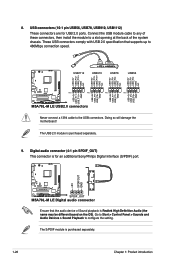
... USB78 USB56 USB+5V USB_P11USB_P11+ GND USB+5V USB_P9USB_P9+ GND USB+5V USB_P7USB_P7+ GND USB+5V USB_P5USB_P5+ GND M5A78L-M LE PIN 1 PIN 1 PIN 1 PIN 1 M5A78L-M LE USB2.0 connectors Never connect a 1394 cable to 480Mbps connection speed. Go to Start > Control Panel > Sounds and... USB56, USB78, USB910, USB1112) These connectors are for an additional Sony/Philips Digital Interface (S/PDIF) port. +5V SPDIFOUT GND M5A78L-M LE SPDIF_OUT M5A78L-M LE Digital audio connector Ensure that supports up to the USB connectors. The USB 2.0 module is purchased separately. 9. 8. Doing so...
... USB78 USB56 USB+5V USB_P11USB_P11+ GND USB+5V USB_P9USB_P9+ GND USB+5V USB_P7USB_P7+ GND USB+5V USB_P5USB_P5+ GND M5A78L-M LE PIN 1 PIN 1 PIN 1 PIN 1 M5A78L-M LE USB2.0 connectors Never connect a 1394 cable to 480Mbps connection speed. Go to Start > Control Panel > Sounds and... USB56, USB78, USB910, USB1112) These connectors are for an additional Sony/Philips Digital Interface (S/PDIF) port. +5V SPDIFOUT GND M5A78L-M LE SPDIF_OUT M5A78L-M LE Digital audio connector Ensure that supports up to the USB connectors. The USB 2.0 module is purchased separately. 9. 8. Doing so...
User Manual
Page 37
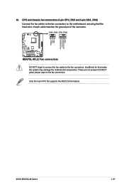
...M5A78L-M LE M5A78L-M LE Fan connectors DO NOT forget to connect the fan cables to the fan connectors on the fan connectors. Insufficient air flow inside the system may damage the motherboard components. CPU and chassis fan connectors (4-pin CPU_FAN and 3-pin CHA_FAN) Connect the fan cables to the fan connectors. ASUS M5A78L...-M Series 1-27 These are not jumpers! Only the 4-pin CPU fan supports the ASUS Q-Fan feature. Rotation +12V GND CPU FAN PWM CPU FAN IN CPU FAN PWR GND...
...M5A78L-M LE M5A78L-M LE Fan connectors DO NOT forget to connect the fan cables to the fan connectors on the fan connectors. Insufficient air flow inside the system may damage the motherboard components. CPU and chassis fan connectors (4-pin CPU_FAN and 3-pin CHA_FAN) Connect the fan cables to the fan connectors. ASUS M5A78L...-M Series 1-27 These are not jumpers! Only the 4-pin CPU fan supports the ASUS Q-Fan feature. Rotation +12V GND CPU FAN PWM CPU FAN IN CPU FAN PWR GND...
User Manual
Page 40
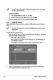
... Flash 2 The ASUS EZ Flash 2 feature allows you start using this utility, download the latest BIOS file from a file, then click Next. ASUSTek EZ Flash 2 BIOS ROM Utility V3.44 FLASH TYPE: WINBOND W25X/Q16 Current ROM BOARD: M5A78L-M LE VER: 0205 (H:00 B:02) DATE: 04/22/2011 Update...the BIOS setup program. To update the BIOS using an OS‑based utility. Press to update the BIOS without using EZ Flash 2: 1. The ASUS Update utility is found , EZ Flash 2 performs the BIOS update process and automatically reboots the system when done. 2-2 Chapter 2: BIOS information b. Go...
... Flash 2 The ASUS EZ Flash 2 feature allows you start using this utility, download the latest BIOS file from a file, then click Next. ASUSTek EZ Flash 2 BIOS ROM Utility V3.44 FLASH TYPE: WINBOND W25X/Q16 Current ROM BOARD: M5A78L-M LE VER: 0205 (H:00 B:02) DATE: 04/22/2011 Update...the BIOS setup program. To update the BIOS using an OS‑based utility. Press to update the BIOS without using EZ Flash 2: 1. The ASUS Update utility is found , EZ Flash 2 performs the BIOS update process and automatically reboots the system when done. 2-2 Chapter 2: BIOS information b. Go...
User Manual
Page 41
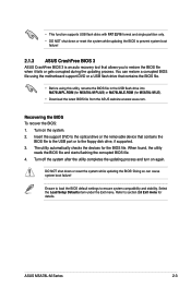
... drive or the removable device that allows you to section 2.8 Exit menu for the BIOS file. The utility automatically checks the devices for details. ASUS M5A78L-M Series 2-3 • This function supports USB flash disks with FAT 32/16 format and single partition only. • DO NOT shut down... using this utility, rename the BIOS file in the USB flash drive into MA78LMPL.ROM (for M5A78L-M PLUS) or MA78LMLE.ROM (for M5A78L-M LE). • Download the latest BIOS file from the ASUS website at www.asus.com. Ensure to load the BIOS default settings to the floppy disk drive, if supported. 3....
... drive or the removable device that allows you to section 2.8 Exit menu for the BIOS file. The utility automatically checks the devices for details. ASUS M5A78L-M Series 2-3 • This function supports USB flash disks with FAT 32/16 format and single partition only. • DO NOT shut down... using this utility, rename the BIOS file in the USB flash drive into MA78LMPL.ROM (for M5A78L-M PLUS) or MA78LMLE.ROM (for M5A78L-M LE). • Download the latest BIOS file from the ASUS website at www.asus.com. Ensure to load the BIOS default settings to the floppy disk drive, if supported. 3....

User Manual
Page 43
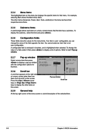
... power management (APM) configuration Boot For changing the system boot configuration Tools For configuring options for that particular menu. ASUS M5A78L-M Series 2-5 2.2.1 BIOS menu screen Menu items Menu bar Configuration fields Main Advanced M5A78L-M LE BIOS Setup Power Boot Tools Exit Main Settings System Time [16:34:30] System Date [Tue 01/11/2011...
... power management (APM) configuration Boot For changing the system boot configuration Tools For configuring options for that particular menu. ASUS M5A78L-M Series 2-5 2.2.1 BIOS menu screen Menu items Menu bar Configuration fields Main Advanced M5A78L-M LE BIOS Setup Power Boot Tools Exit Main Settings System Time [16:34:30] System Date [Tue 01/11/2011...
User Manual
Page 44
... press to display a pop-up window Scroll bar 2.2.9 General help At the top right corner of the menu screen is not user-configurable. Main Advanced M5A78L-M LE BIOS Setup Power Boot Tools Exit Power Settings Suspend Mode ACPI 2.0 Support ACPI APIC support APM Configuration HW Monitor Configuration Anti Surge Support [Auto] [Enabled...
... press to display a pop-up window Scroll bar 2.2.9 General help At the top right corner of the menu screen is not user-configurable. Main Advanced M5A78L-M LE BIOS Setup Power Boot Tools Exit Power Settings Suspend Mode ACPI 2.0 Support ACPI APIC support APM Configuration HW Monitor Configuration Anti Surge Support [Auto] [Enabled...


