
User Manual
Page 1
M4N68T-M LE Motherboard
M4N68T-M LE Motherboard
User Manual
Page 3
Contents Notices...vi Safety information vii About this guide vii M4N68T-M LE specifications summary ix Chapter 1: Product introduction 1.1 Welcome 1-1 1.2 Package contents 1-1 1.3 Special features 1-1 1.3.1 Product highlights 1-1 1.3.2 Innovative ASUS features 1-3 1.4 Before you proceed 1-5 1.5 Motherboard overview 1-6 1.5.1 Placement direction 1-6 1.5.2 Screw holes 1-6 1.5.3 Motherboard layout 1-7 1.5.4 Layout contents 1-7 1.6 Central Processing Unit (CPU 1-8 1.6.1 Installing the CPU 1-8 1.6.2 Installing the heatsink and ...
Contents Notices...vi Safety information vii About this guide vii M4N68T-M LE specifications summary ix Chapter 1: Product introduction 1.1 Welcome 1-1 1.2 Package contents 1-1 1.3 Special features 1-1 1.3.1 Product highlights 1-1 1.3.2 Innovative ASUS features 1-3 1.4 Before you proceed 1-5 1.5 Motherboard overview 1-6 1.5.1 Placement direction 1-6 1.5.2 Screw holes 1-6 1.5.3 Motherboard layout 1-7 1.5.4 Layout contents 1-7 1.6 Central Processing Unit (CPU 1-8 1.6.1 Installing the CPU 1-8 1.6.2 Installing the heatsink and ...

User Manual
Page 8
...manual. These documents are linked with a plus sign (+). Example: ++ viii IMPORTANT: Instructions that you MUST follow to the ASUS contact information. 2. Refer to complete a task. Keys enclosed in ��g��to ��p��...65533;�s�a��n�d��a�d�d��it �e�m�t�o�s�e�le�c�t. Optional documentation Your product package may include optional documentation, such as warranty flyers, that may have ...
...manual. These documents are linked with a plus sign (+). Example: ++ viii IMPORTANT: Instructions that you MUST follow to the ASUS contact information. 2. Refer to complete a task. Keys enclosed in ��g��to ��p��...65533;�s�a��n�d��a�d�d��it �e�m�t�o�s�e�le�c�t. Optional documentation Your product package may include optional documentation, such as warranty flyers, that may have ...
User Manual
Page 9
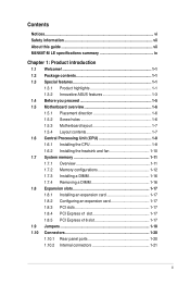
... support 8-channel audio output. resolution of 4GB or more, Windows® 32-bit operating system may only recognize less than 3GB. M4N68T-M LE specifications summary CPU Chipset Front side bus Memory Graphics Expansion slots Storage / RAID LAN Audio USB Back panel I/O ports AMD® ...; 100 series processors AMD® Cool 'n' Quiet™ Technology AMD 64 architecture enables simultaneous 32-bit and 64-bit computing * Refer to www.asus.com for the AMD® CPU support list GeForce 7025 / nForce 630a 2000 / 1600 MT/s HyperTransport™ 1.0 interface Dual-channel memory architecture...
... support 8-channel audio output. resolution of 4GB or more, Windows® 32-bit operating system may only recognize less than 3GB. M4N68T-M LE specifications summary CPU Chipset Front side bus Memory Graphics Expansion slots Storage / RAID LAN Audio USB Back panel I/O ports AMD® ...; 100 series processors AMD® Cool 'n' Quiet™ Technology AMD 64 architecture enables simultaneous 32-bit and 64-bit computing * Refer to www.asus.com for the AMD® CPU support list GeForce 7025 / nForce 630a 2000 / 1600 MT/s HyperTransport™ 1.0 interface Dual-channel memory architecture...
User Manual
Page 10
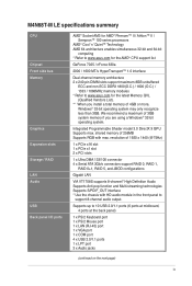
...at 1MHz increment - M4N68T-M LE specifications summary Internal I /O shield 1 x User Manual Drivers ASUS Update ASUS PC Probe II Anti-Virus software (OEM version) MicroATX form factor: 9.6 in x 8.2 in (24.4 cm x 20.8 cm) *Specifications are subject to 550MHz at 1MHz increment ASUS C.P.R. (CPU Parameter... 8Mb Flash ROM, AMI BIOS, PnP, DMI2.0, WfM2.0, ACPI2.0a, SM BIOS 2.5 ASUS EPU-4 Engine ASUS Express Gate ASUS Q-Fan ASUS CrashFree BIOS3 ASUS EZ Flash2 ASUS AI NET2 ASUS MyLogo2 ASUS Turbo Key SFS (Stepless Frequency Selection) - PCIe frequency tuning from 200MHz to change without ...
...at 1MHz increment - M4N68T-M LE specifications summary Internal I /O shield 1 x User Manual Drivers ASUS Update ASUS PC Probe II Anti-Virus software (OEM version) MicroATX form factor: 9.6 in x 8.2 in (24.4 cm x 20.8 cm) *Specifications are subject to 550MHz at 1MHz increment ASUS C.P.R. (CPU Parameter... 8Mb Flash ROM, AMI BIOS, PnP, DMI2.0, WfM2.0, ACPI2.0a, SM BIOS 2.5 ASUS EPU-4 Engine ASUS Express Gate ASUS Q-Fan ASUS CrashFree BIOS3 ASUS EZ Flash2 ASUS AI NET2 ASUS MyLogo2 ASUS Turbo Key SFS (Stepless Frequency Selection) - PCIe frequency tuning from 200MHz to change without ...
User Manual
Page 11
...-core processors with unique L3 cache and delivers better overclocking capabilities with the list below. 1.2 Package contents Check your motherboard package for buying an ASUS® M4N68T-M LE motherboard! ASUS M4N68T-M LE 1-1 Chapter 1 Product introduction 1.1 Welcome! It features dual-channel DDR3 memory support and accelerates data transfer rate up to 2000MT/s via HyperTransport™ 1.0-based system...
...-core processors with unique L3 cache and delivers better overclocking capabilities with the list below. 1.2 Package contents Check your motherboard package for buying an ASUS® M4N68T-M LE motherboard! ASUS M4N68T-M LE 1-1 Chapter 1 Product introduction 1.1 Welcome! It features dual-channel DDR3 memory support and accelerates data transfer rate up to 2000MT/s via HyperTransport™ 1.0-based system...
User Manual
Page 13
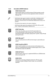
... your system. ASUS M4N68T-M LE 1-3 When installing it on USB HDDs or flash drives, connect the drives to the motherboard USB port before entering the Windows® OS. • ASUS Express Gate supports installation on the system configuration. • ASUS Express Gate supports file uploading from a USB flash disk before entering the OS. ASUS Q-Fan ASUS Q-Fan...
... your system. ASUS M4N68T-M LE 1-3 When installing it on USB HDDs or flash drives, connect the drives to the motherboard USB port before entering the Windows® OS. • ASUS Express Gate supports installation on the system configuration. • ASUS Express Gate supports file uploading from a USB flash disk before entering the OS. ASUS Q-Fan ASUS Q-Fan...

User Manual
Page 15
... pad or in the bag that came with a standby power LED that lights up to the motherboard, peripherals, or components. SB_PWR M4N68T-M LE ON OFF Standby Power Powered Off M4N68T-M LE Onboard LED ASUS M4N68T-M LE 1-5 1.4 Before you proceed Take note of the onboard LED. This is ON, in sleep mode, or in soft-off the ATX...
... pad or in the bag that came with a standby power LED that lights up to the motherboard, peripherals, or components. SB_PWR M4N68T-M LE ON OFF Standby Power Powered Off M4N68T-M LE Onboard LED ASUS M4N68T-M LE 1-5 1.4 Before you proceed Take note of the onboard LED. This is ON, in sleep mode, or in soft-off the ATX...

User Manual
Page 16
The edge with external ports goes to the rear part of the chassis. Doing so can damage the motherboard. Place this side towards the rear of the chassis as indicated in the correct orientation. M4N68T-M LE 1-6 Chapter 1: Product introduction DO NOT overtighten the screws! 1.5 Motherboard overview 1.5.1 Placement direction When installing the motherboard, ensure that you place it into the chassis in the image below. 1.5.2 Screw holes Place six screws into the holes indicated by circles to secure the motherboard to the chassis.
The edge with external ports goes to the rear part of the chassis. Doing so can damage the motherboard. Place this side towards the rear of the chassis as indicated in the correct orientation. M4N68T-M LE 1-6 Chapter 1: Product introduction DO NOT overtighten the screws! 1.5 Motherboard overview 1.5.1 Placement direction When installing the motherboard, ensure that you place it into the chassis in the image below. 1.5.2 Screw holes Place six screws into the holes indicated by circles to secure the motherboard to the chassis.
User Manual
Page 17
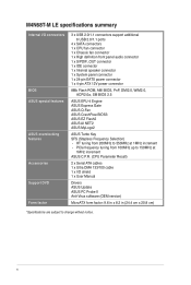
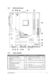
... 7 USBPW1-4 USB34 24.4cm(9.6in) LAN1_USB12 Super I/O CPU_FAN EATXPWR Lithium Cell 3 AUDIO CMOS Power CHA_FAN RTL 8211CL PCIEX16 M4N68T-M LE PCIEX1_1 PCI1 NVIDIA® MCP68 SE 8Mb BIOS 8 CLRTC 2 SATA2 SATA4 PCI2 VIA VT1708S SB_PWR F_PANEL USB56 USB78 USB910 SATA1...fan connectors (4-pin CPU_FAN and 3-pin CHA_FAN) 1-27 12. DDR3 DIMM sockets 1-11 14. Onboard LED 1-5 6. Clear RTC RAM (CLRTC) 1-18 ASUS M4N68T-M LE 1-7 System panel connector (10-1 pin F_PANEL) 1-25 5. Digital audio connector (4-1 pin SPDIF_OUT) 1-27 7. ATX power connectors (24-pin EATXPWR, 4-...
... 7 USBPW1-4 USB34 24.4cm(9.6in) LAN1_USB12 Super I/O CPU_FAN EATXPWR Lithium Cell 3 AUDIO CMOS Power CHA_FAN RTL 8211CL PCIEX16 M4N68T-M LE PCIEX1_1 PCI1 NVIDIA® MCP68 SE 8Mb BIOS 8 CLRTC 2 SATA2 SATA4 PCI2 VIA VT1708S SB_PWR F_PANEL USB56 USB78 USB910 SATA1...fan connectors (4-pin CPU_FAN and 3-pin CHA_FAN) 1-27 12. DDR3 DIMM sockets 1-11 14. Onboard LED 1-5 6. Clear RTC RAM (CLRTC) 1-18 ASUS M4N68T-M LE 1-7 System panel connector (10-1 pin F_PANEL) 1-25 5. Digital audio connector (4-1 pin SPDIF_OUT) 1-27 7. ATX power connectors (24-pin EATXPWR, 4-...
User Manual
Page 18
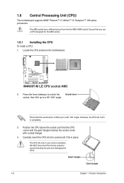
M4N68T-M LE M4N68T-M LE CPU socket AM3 2. Position the CPU above the socket such that you use a CPU designed for the AM3 socket. 1.6.1 Installing the CPU To install a CPU: 1. ...
M4N68T-M LE M4N68T-M LE CPU socket AM3 2. Position the CPU above the socket such that you use a CPU designed for the AM3 socket. 1.6.1 Installing the CPU To install a CPU: 1. ...
User Manual
Page 19
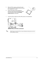
... can also refer to connect the CPU fan connector! 5. When the CPU is locked. 6. ASUS M4N68T-M LE 1-9 You can occur if you fail to secure the CPU. M4N68T-M LE CPU_FAN CPU FAN PWM CPU FAN IN CPU FAN PWR GND M4N68T-M LE CPU fan connector DO NOT forget to section 1.6.2 Installing heatsink and fan for instructions. 7. The...
... can also refer to connect the CPU fan connector! 5. When the CPU is locked. 6. ASUS M4N68T-M LE 1-9 You can occur if you fail to secure the CPU. M4N68T-M LE CPU_FAN CPU FAN PWM CPU FAN IN CPU FAN PWR GND M4N68T-M LE CPU fan connector DO NOT forget to section 1.6.2 Installing heatsink and fan for instructions. 7. The...
User Manual
Page 21
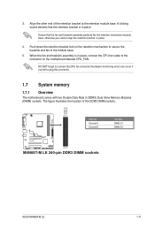
... Rate 3 (DDR3) Dual Inline Memory Modules (DIMM) sockets. Align the other end of the DDR3 DIMM sockets: DIMM_A1 DIMM_B1 M4N68T-M LE Channel Channel A Channel B M4N68T-M LE 240-pin DDR3 DIMM sockets Sockets DIMM_A1 DIMM_B1 ASUS M4N68T-M LE 1-11 Hardware monitoring errors can occur if you cannot snap the retention bracket in place. A clicking sound denotes that the...
... Rate 3 (DDR3) Dual Inline Memory Modules (DIMM) sockets. Align the other end of the DDR3 DIMM sockets: DIMM_A1 DIMM_B1 M4N68T-M LE Channel Channel A Channel B M4N68T-M LE 240-pin DDR3 DIMM sockets Sockets DIMM_A1 DIMM_B1 ASUS M4N68T-M LE 1-11 Hardware monitoring errors can occur if you cannot snap the retention bracket in place. A clicking sound denotes that the...

User Manual
Page 22
... install 4GB or more memory on the motherboard, the actual usable memory for single-channel operation. • Always install DIMMs with the same CAS latency. M4N68T-M LE Motherboard Qualified Vendors Lists (QVL) DDR3-1800(O.C.)MHz capability Vendor Part No. Apacer 78.0AGCD.CDZ(XMP) 2048MB(Kit of 3) SS/ DS Brand Chip NO...
... install 4GB or more memory on the motherboard, the actual usable memory for single-channel operation. • Always install DIMMs with the same CAS latency. M4N68T-M LE Motherboard Qualified Vendors Lists (QVL) DDR3-1800(O.C.)MHz capability Vendor Part No. Apacer 78.0AGCD.CDZ(XMP) 2048MB(Kit of 3) SS/ DS Brand Chip NO...
User Manual
Page 25
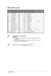
DDR3-1066MHz capability Vendor Part No. Size SS/ DS Brand Chip NO. Visit the ASUS website at www.asus.com for the latest QVL. ASUS M4N68T-M LE 1-15 Crucial CT12864BA1067.8FF 1024MB SS Crucial CT12872BA1067.9FF 1024MB SS Crucial CT25664BA1067.16FF 2048MB DS Crucial CT25672BA1067.18FF 2048MB DS Elpida EBJ51UD8BAFA-AC-E 512MB ...
DDR3-1066MHz capability Vendor Part No. Size SS/ DS Brand Chip NO. Visit the ASUS website at www.asus.com for the latest QVL. ASUS M4N68T-M LE 1-15 Crucial CT12864BA1067.8FF 1024MB SS Crucial CT12872BA1067.9FF 1024MB SS Crucial CT25664BA1067.16FF 2048MB DS Crucial CT25672BA1067.18FF 2048MB DS Elpida EBJ51UD8BAFA-AC-E 512MB ...
User Manual
Page 27
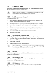
... your motherboard is completely seated on shared slots, ensure that the drivers support "Share IRQ" or that the cards do so may need IRQ assignments. ASUS M4N68T-M LE 1-17 Align the card connector with the screw you removed earlier. 6. See Chapter 2 for the expansion card. When using PCI cards on the slot. 5. The...
... your motherboard is completely seated on shared slots, ensure that the drivers support "Share IRQ" or that the cards do so may need IRQ assignments. ASUS M4N68T-M LE 1-17 Align the card connector with the screw you removed earlier. 6. See Chapter 2 for the expansion card. When using PCI cards on the slot. 5. The...

User Manual
Page 28
CLRTC 12 23 M4N68T-M LE Normal (Default) Clear RTC M4N68T-M LE Clear RTC RAM To erase the RTC RAM: 1. Move the jumper cap from pins 1-2 (default) to overclocking, use the CPU Parameter Recall (C.P.R) feature. After clearing ...
CLRTC 12 23 M4N68T-M LE Normal (Default) Clear RTC M4N68T-M LE Clear RTC RAM To erase the RTC RAM: 1. Move the jumper cap from pins 1-2 (default) to overclocking, use the CPU Parameter Recall (C.P.R) feature. After clearing ...
User Manual
Page 29
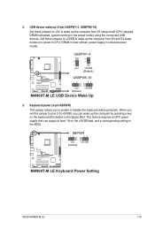
...), you to CPU, DRAM in slow refresh, power supply in low power mode) using the connected USB devices. KBPWR 12 23 +5V +5VSB (Default) M4N68T-M LE M4N68T-M LE Keyboard Power Setting ASUS M4N68T-M LE 1-19 USB device wake-up (3-pin USBPW1-4, USBPW5-10) Set these jumpers to +5VSB to wake up feature. USBPW1-4 12 23 +5V +5VSB...
...), you to CPU, DRAM in slow refresh, power supply in low power mode) using the connected USB devices. KBPWR 12 23 +5V +5VSB (Default) M4N68T-M LE M4N68T-M LE Keyboard Power Setting ASUS M4N68T-M LE 1-19 USB device wake-up (3-pin USBPW1-4, USBPW5-10) Set these jumpers to +5VSB to wake up feature. USBPW1-4 12 23 +5V +5VSB...
User Manual
Page 31
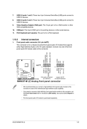
... SENSE2_RETUR AGND NC NC NC AAFP PIN 1 PIN 1 MIC2 MICPWR Line out_R NC Line out_L PORT1 L PORT1 R PORT2 R SENSE_SEND PORT2 L M4N68T-M LE HD-audio-compliant Legacy AC'97 pin definition compliant definition M4N68T-M LE Analog front panel connector • We recommend that supports either High Definition Audio or AC`97 audio standard. These two... capability. • If you connect a high-definition front panel audio module to this connector. 7. This 9-pin COM1 port is for a PS/2 keyboard. 1.10.2 Internal connectors 1. ASUS M4N68T-M LE 1-21
... SENSE2_RETUR AGND NC NC NC AAFP PIN 1 PIN 1 MIC2 MICPWR Line out_R NC Line out_L PORT1 L PORT1 R PORT2 R SENSE_SEND PORT2 L M4N68T-M LE HD-audio-compliant Legacy AC'97 pin definition compliant definition M4N68T-M LE Analog front panel connector • We recommend that supports either High Definition Audio or AC`97 audio standard. These two... capability. • If you connect a high-definition front panel audio module to this connector. 7. This 9-pin COM1 port is for a PS/2 keyboard. 1.10.2 Internal connectors 1. ASUS M4N68T-M LE 1-21

User Manual
Page 32
... GND +3 Volts +12 Volts +12 Volts +5V Standby Power OK PIN 1 GND +5 Volts GND +5 Volts GND +3 Volts +3 Volts PIN 1 M4N68T-M LE ATX power connectors GND +5 Volts +5 Volts +5 Volts -5 Volts GND GND GND PSON# GND -12 Volts +3 Volts • We recommend that you use a PSU ...8209;compliant power supply unit (PSU) with 20-pin and 4-pin power plugs, ensure that the 20-pin power plug can provide at http://support.asus. com/PowerSupplyCalculator/PSCalculator.aspx?SLanguage=en-us for your system, refer to the Recommended Power Supply Wattage Calculator at least 15 A on +12 V and...
... GND +3 Volts +12 Volts +12 Volts +5V Standby Power OK PIN 1 GND +5 Volts GND +5 Volts GND +3 Volts +3 Volts PIN 1 M4N68T-M LE ATX power connectors GND +5 Volts +5 Volts +5 Volts -5 Volts GND GND GND PSON# GND -12 Volts +3 Volts • We recommend that you use a PSU ...8209;compliant power supply unit (PSU) with 20-pin and 4-pin power plugs, ensure that the 20-pin power plug can provide at http://support.asus. com/PowerSupplyCalculator/PSCalculator.aspx?SLanguage=en-us for your system, refer to the Recommended Power Supply Wattage Calculator at least 15 A on +12 V and...


