
User Manual
Page 1
Motherboard M4A785TD-V EVO
Motherboard M4A785TD-V EVO
User Manual
Page 3
Contents Notices...vi Safety information vii About this guide viii M4A785TD-V EVO specifications summary ix Chapter 1: Product introduction 1.1 Welcome 1-1 1.2 Package contents 1-1 1.3 Special features 1-1 1.3.1 Product highlights 1-1 1.3.2 Innovative ASUS features 1-3 1.4 Before you proceed 1-5 1.5 Motherboard overview 1-6 1.5.1 Placement direction 1-6 1.5.2 Screw holes 1-6 1.5.3 Motherboard layout 1-7 1.5.4 Layout contents 1-7 1.6 Central Processing Unit (CPU 1-8 1.6.1 Installing the CPU 1-8 1.6.2 Installing the heatsink and fan 1-10 1.7 System memory...
Contents Notices...vi Safety information vii About this guide viii M4A785TD-V EVO specifications summary ix Chapter 1: Product introduction 1.1 Welcome 1-1 1.2 Package contents 1-1 1.3 Special features 1-1 1.3.1 Product highlights 1-1 1.3.2 Innovative ASUS features 1-3 1.4 Before you proceed 1-5 1.5 Motherboard overview 1-6 1.5.1 Placement direction 1-6 1.5.2 Screw holes 1-6 1.5.3 Motherboard layout 1-7 1.5.4 Layout contents 1-7 1.6 Central Processing Unit (CPU 1-8 1.6.1 Installing the CPU 1-8 1.6.2 Installing the heatsink and fan 1-10 1.7 System memory...
User Manual
Page 9
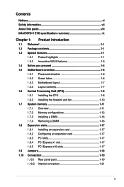
...4GB or more, Windows® 32-bit operating system may only recognize less than 3GB. resolution up to 1920 x 1200 (1080p) - M4A785TD-V EVO specifications summary CPU Chipset Front side bus Memory VGA Expansion slots Storage / RAID LAN AMD® Socket AM3 for AMD® Phenom™ ... x 240-pin DIMM slots support maximum 16GB unbuffered ECC and non-ECC DDR3 1800 (O.C.) / 1600 (O.C.) / 1333 / 1066 MHz memory modules * Refer to www.asus.com for up to 2 PATA devices - 5 x Serial ATA 3Gb/s connectors support RAID 0, RAID 1, RAID 0+1, and JBOD configurations - 1 x eSATA 3Gb/s port...
...4GB or more, Windows® 32-bit operating system may only recognize less than 3GB. resolution up to 1920 x 1200 (1080p) - M4A785TD-V EVO specifications summary CPU Chipset Front side bus Memory VGA Expansion slots Storage / RAID LAN AMD® Socket AM3 for AMD® Phenom™ ... x 240-pin DIMM slots support maximum 16GB unbuffered ECC and non-ECC DDR3 1800 (O.C.) / 1600 (O.C.) / 1333 / 1066 MHz memory modules * Refer to www.asus.com for up to 2 PATA devices - 5 x Serial ATA 3Gb/s connectors support RAID 0, RAID 1, RAID 0+1, and JBOD configurations - 1 x eSATA 3Gb/s port...

User Manual
Page 10
M4A785TD-V EVO specifications summary Audio USB 1394 ASUS unique features Other features ASUS exclusive overclocking features VIA® VT1708S High Definition Audio 8-channel CODEC Supports Jack-detect, Multi-streaming, and Front Panel Jack-Retasking technologies Optical S/PDIF Out port at back I/O Supports up to 400MHz at 1MHz increment - ASUS Fanless Design: Stylish heat sink solution - FSB...
M4A785TD-V EVO specifications summary Audio USB 1394 ASUS unique features Other features ASUS exclusive overclocking features VIA® VT1708S High Definition Audio 8-channel CODEC Supports Jack-detect, Multi-streaming, and Front Panel Jack-Retasking technologies Optical S/PDIF Out port at back I/O Supports up to 400MHz at 1MHz increment - ASUS Fanless Design: Stylish heat sink solution - FSB...
User Manual
Page 11
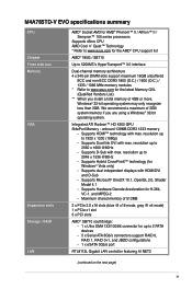
M4A785TD-V EVO specifications summary Back panel I/O ports Internal I/O connectors BIOS Manageability Accessories Support DVD Form factor 1 x PS/2 Keyboard / Mouse Combo port 1 x Optical S/PDIF Out port 1 x HDMI port 1 x ... PME, WOR by Ring, PXE 1 x Ultra DMA 133/100/66 cable 4 x Serial ATA cables 1 x I/O shield 1 x User Manual Drivers ASUS Express Gate ASUS Update ASUS PC Probe II AMD OverDrive Utility (AOD) Anti-Virus software (OEM version) ATX form factor: 12 in x 9.6 in (30.5 cm x 24.4 cm) *Specifications are subject to change without notice. xi
M4A785TD-V EVO specifications summary Back panel I/O ports Internal I/O connectors BIOS Manageability Accessories Support DVD Form factor 1 x PS/2 Keyboard / Mouse Combo port 1 x Optical S/PDIF Out port 1 x HDMI port 1 x ... PME, WOR by Ring, PXE 1 x Ultra DMA 133/100/66 cable 4 x Serial ATA cables 1 x I/O shield 1 x User Manual Drivers ASUS Express Gate ASUS Update ASUS PC Probe II AMD OverDrive Utility (AOD) Anti-Virus software (OEM version) ATX form factor: 12 in x 9.6 in (30.5 cm x 24.4 cm) *Specifications are subject to change without notice. xi
User Manual
Page 13
...another standout in your package with the list below. 1.2 Package contents Check your motherboard package for buying an ASUS® M4A785TD-V EVO motherboard! The motherboard delivers a host of new features and latest technologies, making it , check the... capabilities. ASUS M4A785TD-V EVO 1-1 Before you for the following items. Motherboard Cables Accessories Application DVD Documentation ASUS M4A785TD-V EVO motherboard 4 x Serial ATA cables 1 x Ultra DMA 133/100/66 cable 1 x I/O shield ASUS motherboard Support DVD User Manual If any of ASUS quality motherboards! It is...
...another standout in your package with the list below. 1.2 Package contents Check your motherboard package for buying an ASUS® M4A785TD-V EVO motherboard! The motherboard delivers a host of new features and latest technologies, making it , check the... capabilities. ASUS M4A785TD-V EVO 1-1 Before you for the following items. Motherboard Cables Accessories Application DVD Documentation ASUS M4A785TD-V EVO motherboard 4 x Serial ATA cables 1 x Ultra DMA 133/100/66 cable 1 x I/O shield ASUS motherboard Support DVD User Manual If any of ASUS quality motherboards! It is...
User Manual
Page 15
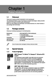
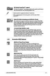
...After the easy setup, Turbo Key boosts performances without exiting or rebooting the OS; ASUS M4A785TD-V EVO 1-3 Innovative ASUS features ASUS 8+2 Phase Power Design To fully unleash the AM3 CPU's potential, the ASUS M4 Series motherboards have adopted a brand-new 8-phase VRM power design which means there will be no... more confusion of real-time OC-now a reality with just a few clicks away. ASUS TurboV Feel the adrenaline rush of Line...
...After the easy setup, Turbo Key boosts performances without exiting or rebooting the OS; ASUS M4A785TD-V EVO 1-3 Innovative ASUS features ASUS 8+2 Phase Power Design To fully unleash the AM3 CPU's potential, the ASUS M4 Series motherboards have adopted a brand-new 8-phase VRM power design which means there will be no... more confusion of real-time OC-now a reality with just a few clicks away. ASUS TurboV Feel the adrenaline rush of Line...
User Manual
Page 17
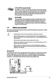
...the power cable before touching any motherboard component. Onboard LED The motherboard comes with the component. • Before you install or remove any component, switch off mode. The illustration below shows the location of Hazardous Substances (RoHS). ASUS M4A785TD-V EVO 1-5 Failure to do so may...proceed Take note of the following precautions before you install motherboard components or change any motherboard settings. • Unplug the power cord from the wall socket before removing or plugging in soft-off the ATX power supply and detach its packaging comply with the ...
...the power cable before touching any motherboard component. Onboard LED The motherboard comes with the component. • Before you install or remove any component, switch off mode. The illustration below shows the location of Hazardous Substances (RoHS). ASUS M4A785TD-V EVO 1-5 Failure to do so may...proceed Take note of the following precautions before you install motherboard components or change any motherboard settings. • Unplug the power cord from the wall socket before removing or plugging in soft-off the ATX power supply and detach its packaging comply with the ...
User Manual
Page 19
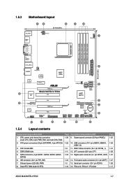
... Front panel audio connector (10-1 pin AAFP) 1-5 15. 1.5.3 Motherboard layout 1.5.4 Layout contents Connectors/Jumpers/Slots/LED 1. Onboard power LED (SB_PWR) 8. System panel connector (20-8 pin PANEL) 1-22 10. PCIe x16 / PCIe x1 / PCI slots Page 1-25 1-26 1-21 1-26 1-27 1-27 1-28 1-17 ASUS M4A785TD-V EVO 1-7 CPU Socket AM3 4. LPT connector (26-1 pin LPT.... CPU, power, and chassis fan connectors (4-pin CPU_FAN, 3-pin PWR_FAN, and 3-pin CHA_FAN) 2. Clear RTC RAM (3-pin CLRTC) Page Connectors/Jumpers/Slots/LED 1-28 9. ATX power connectors (24-pin EATXPWR, 4-pin ATX12V) 3.
... Front panel audio connector (10-1 pin AAFP) 1-5 15. 1.5.3 Motherboard layout 1.5.4 Layout contents Connectors/Jumpers/Slots/LED 1. Onboard power LED (SB_PWR) 8. System panel connector (20-8 pin PANEL) 1-22 10. PCIe x16 / PCIe x1 / PCI slots Page 1-25 1-26 1-21 1-26 1-27 1-27 1-28 1-17 ASUS M4A785TD-V EVO 1-7 CPU Socket AM3 4. LPT connector (26-1 pin LPT.... CPU, power, and chassis fan connectors (4-pin CPU_FAN, 3-pin PWR_FAN, and 3-pin CHA_FAN) 2. Clear RTC RAM (3-pin CLRTC) Page Connectors/Jumpers/Slots/LED 1-28 9. ATX power connectors (24-pin EATXPWR, 4-pin ATX12V) 3.
User Manual
Page 21
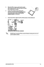
You can occur if you fail to indicate that comes with the heatsink package. Connect the CPU fan cable to connect the CPU fan connector! The lever clicks on the motherboard. ASUS M4A785TD-V EVO 1-9 DO NOT forget to the CPU_FAN connector on the side tab to plug this connector. When the CPU is locked. 6. Hardware monitoring errors can also refer to secure the CPU. Install a CPU heatsink and fan following the instructions that it is in place, push down the socket lever to section 1.6.2 Installing heatsink and fan for instructions. 7. 5.
You can occur if you fail to indicate that comes with the heatsink package. Connect the CPU fan cable to connect the CPU fan connector! The lever clicks on the motherboard. ASUS M4A785TD-V EVO 1-9 DO NOT forget to the CPU_FAN connector on the side tab to plug this connector. When the CPU is locked. 6. Hardware monitoring errors can also refer to secure the CPU. Install a CPU heatsink and fan following the instructions that it is in place, push down the socket lever to section 1.6.2 Installing heatsink and fan for instructions. 7. 5.

User Manual
Page 23
... on the retention mechanism to secure the heatsink and fan to plug this connector. 1.7 System memory 1.7.1 Overview This motherboard comes with less power consumption. Push down the retention bracket lock on the motherboard labeled CPU_FAN. Hardware monitoring errors can occur if you cannot snap the retention bracket in place. A clicking sound denotes... to connect the CPU fan connector! Align the other end of the DDR3 DIMM sockets: Channel Channel A Channel B Sockets DIMM_A1 and DIMM_A2 DIMM_B1 and DIMM_B2 ASUS M4A785TD-V EVO 1-11
... on the retention mechanism to secure the heatsink and fan to plug this connector. 1.7 System memory 1.7.1 Overview This motherboard comes with less power consumption. Push down the retention bracket lock on the motherboard labeled CPU_FAN. Hardware monitoring errors can occur if you cannot snap the retention bracket in place. A clicking sound denotes... to connect the CPU fan connector! Align the other end of the DDR3 DIMM sockets: Channel Channel A Channel B Sockets DIMM_A1 and DIMM_A2 DIMM_B1 and DIMM_B2 ASUS M4A785TD-V EVO 1-11

User Manual
Page 24
... up of memory, we recommend that you install 4GB or more memory on the motherboard. • This motherboard does not support DIMMs made up to install 4GB or more memory on the motherboard, the actual usable memory for the dual-channel configuration. Size SS/ Chip Chip NO. The system... limitation on 32-bit Windows® OS, when you do any of 4GB DIMMs on Windows® XP Professional x64 and Vista x64 editions. M4A785TD-V EVO Motherboard Qualified Vendors Lists (QVL) DDR3-1866(O.C.)MHz capability Vendor Part No. Use a 64-bit Windows® OS if you are using a 32...
... up of memory, we recommend that you install 4GB or more memory on the motherboard. • This motherboard does not support DIMMs made up to install 4GB or more memory on the motherboard, the actual usable memory for the dual-channel configuration. Size SS/ Chip Chip NO. The system... limitation on 32-bit Windows® OS, when you do any of 4GB DIMMs on Windows® XP Professional x64 and Vista x64 editions. M4A785TD-V EVO Motherboard Qualified Vendors Lists (QVL) DDR3-1866(O.C.)MHz capability Vendor Part No. Use a 64-bit Windows® OS if you are using a 32...

User Manual
Page 25
...; • • • • • • • • • • • • • • • • • • • • (continued on the next page) ASUS M4A785TD-V EVO 1-13 CL A-Data AD31600X002GMU 4096MB(Kit of 2) DS Corsair CM3X1G1600C9DHX 2048MB(Kit of 2) SS CRUCIAL BL12864BA1608.8SFB(XMP) 3072MB(Kit of 3) SS CRUCIAL BL12864BE2009.8SFB3...
...; • • • • • • • • • • • • • • • • • • • • (continued on the next page) ASUS M4A785TD-V EVO 1-13 CL A-Data AD31600X002GMU 4096MB(Kit of 2) DS Corsair CM3X1G1600C9DHX 2048MB(Kit of 2) SS CRUCIAL BL12864BA1608.8SFB(XMP) 3072MB(Kit of 3) SS CRUCIAL BL12864BE2009.8SFB3...

User Manual
Page 27
Visit the ASUS website at www.asus.com for the latest QVL. ASUS M4A785TD-V EVO 1-15 CL SS elpida J5308BASE-AC-E N/A SS elpida J5308BASE-AC-E N/A SS G.SKILL Heat-Sink Package N/A SS elpida J1108BABG-DJ-E 7 SS elpida J5308BASE-AE-E S 7 DS elpida ...
Visit the ASUS website at www.asus.com for the latest QVL. ASUS M4A785TD-V EVO 1-15 CL SS elpida J5308BASE-AC-E N/A SS elpida J5308BASE-AC-E N/A SS G.SKILL Heat-Sink Package N/A SS elpida J1108BABG-DJ-E 7 SS elpida J5308BASE-AE-E S 7 DS elpida ...
User Manual
Page 29
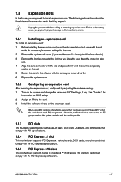
...Install the software drivers for later use . Assign an IRQ to the chassis with the screw you intend to install expansion cards. ASUS M4A785TD-V EVO 1-17 Remove the bracket opposite the slot that you removed earlier. 6. When using PCI cards on the system and change the necessary.... 1. See Chapter 2 for the card. 2. Align the card connector with the PCI Express specifications. 1.8.5 PCI Express x16 slots This motherboard supports two ATI CrossFireX™ PCI Express x16 graphics cards that they support. Otherwise, conflicts will arise between the two PCI groups, making...
...Install the software drivers for later use . Assign an IRQ to the chassis with the screw you intend to install expansion cards. ASUS M4A785TD-V EVO 1-17 Remove the bracket opposite the slot that you removed earlier. 6. When using PCI cards on the system and change the necessary.... 1. See Chapter 2 for the card. 2. Align the card connector with the PCI Express specifications. 1.8.5 PCI Express x16 slots This motherboard supports two ATI CrossFireX™ PCI Express x16 graphics cards that they support. Otherwise, conflicts will arise between the two PCI groups, making...

User Manual
Page 31
... ORANGE Linked BLINKING Data activity Speed LED Status OFF ORANGE GREEN Description 10Mbps connection 100Mbps connection 1Gbps connection ACT/LINK SPEED LED LED LAN port 6. ASUS M4A785TD-V EVO 1-19 1.10 1.10.1 Connectors Rear panel ports 1. Video Graphics Adapter (VGA) port. This port connects to an external audio output device via an optical S/PDIF...
... ORANGE Linked BLINKING Data activity Speed LED Status OFF ORANGE GREEN Description 10Mbps connection 100Mbps connection 1Gbps connection ACT/LINK SPEED LED LED LAN port 6. ASUS M4A785TD-V EVO 1-19 1.10 1.10.1 Connectors Rear panel ports 1. Video Graphics Adapter (VGA) port. This port connects to an external audio output device via an optical S/PDIF...

User Manual
Page 33
USB 2.0 ports 5 and 6. Doing so will damage the motherboard! CPU DIMM BIOS setup Suggested list AMD® Phenom™ II x3 720 DDR3 1333 (1GB or higher) Frame Buffer Size--256MB or higher File ...-1 pin IE1394_1) This connector is for USB 2.0 devices. 1.10.2 Internal connectors 1. These two 4-pin Universal Serial Bus (USB) ports are for an IEEE 1394a port. ASUS M4A785TD-V EVO 1-21 Never connect a USB cable to use HDCP compliant devices and software. 17. Playback of the system chassis. Connect the IEEE 1394a module cable to...
USB 2.0 ports 5 and 6. Doing so will damage the motherboard! CPU DIMM BIOS setup Suggested list AMD® Phenom™ II x3 720 DDR3 1333 (1GB or higher) Frame Buffer Size--256MB or higher File ...-1 pin IE1394_1) This connector is for USB 2.0 devices. 1.10.2 Internal connectors 1. These two 4-pin Universal Serial Bus (USB) ports are for an IEEE 1394a port. ASUS M4A785TD-V EVO 1-21 Never connect a USB cable to use HDCP compliant devices and software. 17. Playback of the system chassis. Connect the IEEE 1394a module cable to...
User Manual
Page 35
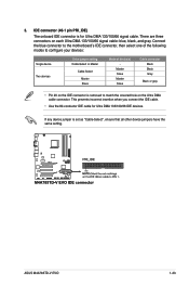
There are three connectors on the Ultra DMA cable connector. ASUS M4A785TD-V EVO 1-23 IDE connector (40-1 pin PRI_IDE) The onboard IDE connector is for Ultra DMA 133/100/66 IDE devices. Master Slave Master Slave Cable connector ... devices: Single device Two devices Drive jumper setting Cable-Select or Master Cable-Select Master Slave Mode of device(s) - Connect the blue connector to the motherboard's IDE connector, then select one of the following modes to match the covered hole on each Ultra DMA 133/100/66 signal cable: blue, black...
There are three connectors on the Ultra DMA cable connector. ASUS M4A785TD-V EVO 1-23 IDE connector (40-1 pin PRI_IDE) The onboard IDE connector is for Ultra DMA 133/100/66 IDE devices. Master Slave Master Slave Cable connector ... devices: Single device Two devices Drive jumper setting Cable-Select or Master Cable-Select Master Slave Mode of device(s) - Connect the blue connector to the motherboard's IDE connector, then select one of the following modes to match the covered hole on each Ultra DMA 133/100/66 signal cable: blue, black...
User Manual
Page 37
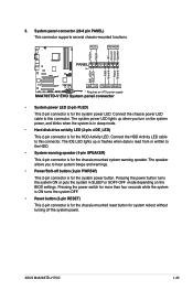
... is for the chassis-mounted reset button for system reboot without turning off button (2-pin PWRSW) This 2-pin connector is for the system power LED. ASUS M4A785TD-V EVO 1-25 Connect the chassis power LED cable to hear system beeps and warnings. • Power/Soft-off the system power.
... is for the chassis-mounted reset button for system reboot without turning off button (2-pin PWRSW) This 2-pin connector is for the system power LED. ASUS M4A785TD-V EVO 1-25 Connect the chassis power LED cable to hear system beeps and warnings. • Power/Soft-off the system power.

User Manual
Page 39
... purchased separately. 9. ASUS M4A785TD-V EVO 1-27 Ensure that you want to connect a high definition front panel audio module to this connector to configure the setting. See section 2.4.4 Onboard Device Configuration for a chassis-mounted front panel audio I /O module cable to this connector. • We recommend that the audio device of the motherboard high-definition audio...
... purchased separately. 9. ASUS M4A785TD-V EVO 1-27 Ensure that you want to connect a high definition front panel audio module to this connector to configure the setting. See section 2.4.4 Onboard Device Configuration for a chassis-mounted front panel audio I /O module cable to this connector. • We recommend that the audio device of the motherboard high-definition audio...


