
User Manual
Page 4
Contents 1.11 Software support 1-28 1.11.1 Installing an operating system 1-28 1.11.2 Support DVD information 1-28 Chapter 2: BIOS information 2.1 Managing and updating your BIOS 2-1 2.1.1 ASUS Update utility 2-1 2.1.2 ASUS EZ Flash 2 utility 2-3 2.1.3 ASUS CrashFree BIOS utility 2-4 2.2 BIOS setup program 2-5 2.2.1 BIOS menu screen 2-6 2.2.2 Menu bar 2-6 2.2.3 Navigation keys 2-6 2.2.4 Menu items 2-7 2.2.5 Submenu items 2-7 2.2.6 Configuration fields 2-7 2.2.7 Pop-up window 2-7 2.2.8 Scroll bar 2-7 2.2.9 General help 2-7 2.3 Main...
Contents 1.11 Software support 1-28 1.11.1 Installing an operating system 1-28 1.11.2 Support DVD information 1-28 Chapter 2: BIOS information 2.1 Managing and updating your BIOS 2-1 2.1.1 ASUS Update utility 2-1 2.1.2 ASUS EZ Flash 2 utility 2-3 2.1.3 ASUS CrashFree BIOS utility 2-4 2.2 BIOS setup program 2-5 2.2.1 BIOS menu screen 2-6 2.2.2 Menu bar 2-6 2.2.3 Navigation keys 2-6 2.2.4 Menu items 2-7 2.2.5 Submenu items 2-7 2.2.6 Configuration fields 2-7 2.2.7 Pop-up window 2-7 2.2.8 Scroll bar 2-7 2.2.9 General help 2-7 2.3 Main...

User Manual
Page 8
...guide contains the following parts: • Chapter 1: Product introduction This chapter describes the features of the BIOS parameters are not damaged. Detailed descriptions of the motherboard and the new technology it , carefully read all the manuals that came with the product, contact ...away from connectors, slots, sockets and circuitry. • Avoid dust, humidity, and temperature extremes. Operation safety • Before installing the motherboard and adding devices on a stable surface. • If you encounter technical problems with the package. • Before using the product,...
...guide contains the following parts: • Chapter 1: Product introduction This chapter describes the features of the BIOS parameters are not damaged. Detailed descriptions of the motherboard and the new technology it , carefully read all the manuals that came with the product, contact ...away from connectors, slots, sockets and circuitry. • Avoid dust, humidity, and temperature extremes. Operation safety • Before installing the motherboard and adding devices on a stable surface. • If you encounter technical problems with the package. • Before using the product,...

User Manual
Page 11
... EATX power connector 1 x 4-pin ATX 12V power connector 8Mb Flash ROM, AMI BIOS, PnP, DMI2.0, WfM2.0, ACPI2.0a, SM BIOS 2.5 ASUS Q-Fan ASUS CrashFree BIOS3 ASUS EZ Flash2 ASUS MyLogo2 ASUS Express Gate ASUS AI NET2 ASUS EPU-4 Engine ASUS Turbo Key SFS (Stepless Frequency Selection) supports: - PCIe frequency tuning from 200MHz to change without notice. M4A77TD specifications summary Back panel I/O ports...
... EATX power connector 1 x 4-pin ATX 12V power connector 8Mb Flash ROM, AMI BIOS, PnP, DMI2.0, WfM2.0, ACPI2.0a, SM BIOS 2.5 ASUS Q-Fan ASUS CrashFree BIOS3 ASUS EZ Flash2 ASUS MyLogo2 ASUS Express Gate ASUS AI NET2 ASUS EPU-4 Engine ASUS Turbo Key SFS (Stepless Frequency Selection) supports: - PCIe frequency tuning from 200MHz to change without notice. M4A77TD specifications summary Back panel I/O ports...

User Manual
Page 16
... 1: Product introduction C.P.R. Green ASUS This motherboard and its packaging comply with the ASUS vision of Hazardous Substances (RoHS). ASUS AI NET2 ASUS AI NET2 remotely detects the cable connection immediately after you to their default settings. ASUS Q-Fan ASUS Q-Fan technology intelligently adjusts the... CPU fan speed according to system loading to open the system chassis and clear the RTC data. ASUS CrashFree BIOS 3 ASUS CrashFree BIOS 3 is a unique power saving technology that contains the BIOS file. ...
... 1: Product introduction C.P.R. Green ASUS This motherboard and its packaging comply with the ASUS vision of Hazardous Substances (RoHS). ASUS AI NET2 ASUS AI NET2 remotely detects the cable connection immediately after you to their default settings. ASUS Q-Fan ASUS Q-Fan technology intelligently adjusts the... CPU fan speed according to system loading to open the system chassis and clear the RTC data. ASUS CrashFree BIOS 3 ASUS CrashFree BIOS 3 is a unique power saving technology that contains the BIOS file. ...
User Manual
Page 19
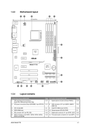
...ATX power connectors (24-pin EATXPWR, 4-pin ATX12V) 3. Clear RTC RAM (3-pin CLRTC) 1-11 10. Front panel audio connector (10-1 pin AAFP) Page 1-24 1-25 1-18 1-5 1-26 1-26 ASUS M4A77TD... 1-7 CPU and chassis fan connectors (4-pin CPU_FAN and 3-pin CHA_FAN) 2. CPU Socket AM3 4. SATA connectors (7-pin SATA1, SATA2, SATA3, SATA4, SATA5, and SATA6) Page Connectors/Jumpers/Slots/LED 1-27 7. Digital audio connector (4-1 pin SPDIF_OUT) 1-23 12. Onboard power LED (SB_PWR) 1-22 11. 1.5.3 Motherboard... M4A77TD AMD® SB710 Lithium Cell CMOS Power Super I/O PCI1 PCI2 8Mb BIOS ...
...ATX power connectors (24-pin EATXPWR, 4-pin ATX12V) 3. Clear RTC RAM (3-pin CLRTC) 1-11 10. Front panel audio connector (10-1 pin AAFP) Page 1-24 1-25 1-18 1-5 1-26 1-26 ASUS M4A77TD... 1-7 CPU and chassis fan connectors (4-pin CPU_FAN and 3-pin CHA_FAN) 2. CPU Socket AM3 4. SATA connectors (7-pin SATA1, SATA2, SATA3, SATA4, SATA5, and SATA6) Page Connectors/Jumpers/Slots/LED 1-27 7. Digital audio connector (4-1 pin SPDIF_OUT) 1-23 12. Onboard power LED (SB_PWR) 1-22 11. 1.5.3 Motherboard... M4A77TD AMD® SB710 Lithium Cell CMOS Power Super I/O PCI1 PCI2 8Mb BIOS ...
User Manual
Page 29
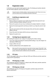
... removed earlier. 6. Unplug the power cord before adding or removing expansion cards. Turn on the slot. 5. ASUS M4A77TD 1-17 Remove the system unit cover (if your motherboard is completely seated on the system and change the necessary BIOS settings, if any. Remove the bracket opposite the slot that they support. See Chapter 2 for the...
... removed earlier. 6. Unplug the power cord before adding or removing expansion cards. Turn on the slot. 5. ASUS M4A77TD 1-17 Remove the system unit cover (if your motherboard is completely seated on the system and change the necessary BIOS settings, if any. Remove the bracket opposite the slot that they support. See Chapter 2 for the...

User Manual
Page 30
You can automatically reset parameter settings to pins 1-2. 3. M4A77TD CLRTC 12 23 Normal (Default) M4A77TD Clear RTC RAM Clear RTC To erase the RTC RAM: 1. Turn OFF ...which include system setup information such as system passwords. Shut down the key during the boot process and enter BIOS setup to clear the CMOS RTC RAM data. The onboard button cell battery powers the RAM data in CMOS.... Hold down and reboot the system so the BIOS can clear the CMOS memory of date, time, and system setup parameters by erasing the CMOS RTC RAM...
You can automatically reset parameter settings to pins 1-2. 3. M4A77TD CLRTC 12 23 Normal (Default) M4A77TD Clear RTC RAM Clear RTC To erase the RTC RAM: 1. Turn OFF ...which include system setup information such as system passwords. Shut down the key during the boot process and enter BIOS setup to clear the CMOS RTC RAM data. The onboard button cell battery powers the RAM data in CMOS.... Hold down and reboot the system so the BIOS can clear the CMOS memory of date, time, and system setup parameters by erasing the CMOS RTC RAM...
User Manual
Page 35
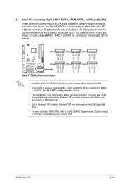
... in the support DVD. See 2.3.4 SATA Configuration for Serial ATA 3Gb/s hard disk and optical disk drives. ASUS M4A77TD 1-23 The data transfer rate of the SATA connectors to create a SATA RAID set, set the type of ... 0+1 set . • Due to the RA ID/AHCI Supplementary Guide included in the folder named Manual in the BIOS. You could use a USB floppy disk drive when installing Windows® XP operating system on RAID/AHCI, refer to...) These connectors are for the Serial ATA signal cables for details. • The motherboard does not provide a floppy disk drive connector.
... in the support DVD. See 2.3.4 SATA Configuration for Serial ATA 3Gb/s hard disk and optical disk drives. ASUS M4A77TD 1-23 The data transfer rate of the SATA connectors to create a SATA RAID set, set the type of ... 0+1 set . • Due to the RA ID/AHCI Supplementary Guide included in the folder named Manual in the BIOS. You could use a USB floppy disk drive when installing Windows® XP operating system on RAID/AHCI, refer to...) These connectors are for the Serial ATA signal cables for details. • The motherboard does not provide a floppy disk drive connector.

User Manual
Page 36
...speaker. System panel connector (20-8 pin PANEL) This connector supports several chassis-mounted functions. The speaker allows you turn on the BIOS settings. Connect the chassis power LED cable to this connector. Connect the HDD Activity LED cable to this connector. Pressing the ...turning off button This 2-pin connector is for the system power button. PWR Ground Reset Ground PANEL PIN 1 M4A77TD IDE_LED PWRSW RESET * Requires an ATX power supply M4A77TD System panel connector • System power LED This 2-pin connector is for the system power LED. Pressing the...
...speaker. System panel connector (20-8 pin PANEL) This connector supports several chassis-mounted functions. The speaker allows you turn on the BIOS settings. Connect the chassis power LED cable to this connector. Connect the HDD Activity LED cable to this connector. Pressing the ...turning off button This 2-pin connector is for the system power button. PWR Ground Reset Ground PANEL PIN 1 M4A77TD IDE_LED PWRSW RESET * Requires an ATX power supply M4A77TD System panel connector • System power LED This 2-pin connector is for the system power LED. Pressing the...

User Manual
Page 38
...this connector, set the Front Panel Select item in the BIOS to [HD Audio]. See section 2.4.4 Onboard Device Configuration for an additional Sony/Philips Digital Interface (S/PDIF) port. +5V SPDIFOUT GND M4A77TD SPDIF_OUT M4A77TD Digital audio connector Ensure that supports either High Definition Audio or... M4A77TD Front panel audio connector Legacy AC'97 compliant definition • We recommend that you connect a high-definition front panel audio module to this connector to avail of the front panel audio I /O module is purchased separately. 7. Connect one end of the motherboard high...
...this connector, set the Front Panel Select item in the BIOS to [HD Audio]. See section 2.4.4 Onboard Device Configuration for an additional Sony/Philips Digital Interface (S/PDIF) port. +5V SPDIFOUT GND M4A77TD SPDIF_OUT M4A77TD Digital audio connector Ensure that supports either High Definition Audio or... M4A77TD Front panel audio connector Legacy AC'97 compliant definition • We recommend that you connect a high-definition front panel audio module to this connector to avail of the front panel audio I /O module is purchased separately. 7. Connect one end of the motherboard high...
User Manual
Page 41
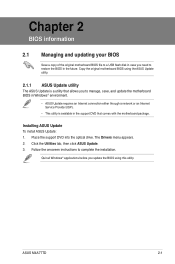
The Drivers menu appears. 2. ASUS M4A77TD 2-1 Chapter 2 BIOS information 2.1 Managing and updating your BIOS Save a copy of the original motherboard BIOS file to a USB flash disk in case you to manage, save, and update the motherboard BIOS in Windows® environment. • ASUS Update requires an Internet connection either through a network or an Internet Service Provider (ISP). • This utility...
The Drivers menu appears. 2. ASUS M4A77TD 2-1 Chapter 2 BIOS information 2.1 Managing and updating your BIOS Save a copy of the original motherboard BIOS file to a USB flash disk in case you to manage, save, and update the motherboard BIOS in Windows® environment. • ASUS Update requires an Internet connection either through a network or an Internet Service Provider (ISP). • This utility...

User Manual
Page 42
... a. c. Always update the utility to complete the updating process. 2-2 Chapter 2: BIOS information Updating from the Internet, then click Next. Select Update BIOS from the Internet a. The ASUS Update utility is capable of the following methods: Updating from a file, then click Next.... its features. Locate the BIOS file from the Open window, then click Open. 3. From the Windows® desktop, click Start > Programs > ASUS > ASUS Update > ASUS Update to download then click Next. b. b. Updating the BIOS To update the BIOS: 1. Select the ASUS FTP site nearest you want...
... a. c. Always update the utility to complete the updating process. 2-2 Chapter 2: BIOS information Updating from the Internet, then click Next. Select Update BIOS from the Internet a. The ASUS Update utility is capable of the following methods: Updating from a file, then click Next.... its features. Locate the BIOS file from the Open window, then click Open. 3. From the Windows® desktop, click Start > Programs > ASUS > ASUS Update > ASUS Update to download then click Next. b. b. Updating the BIOS To update the BIOS: 1. Select the ASUS FTP site nearest you want...
User Manual
Page 43
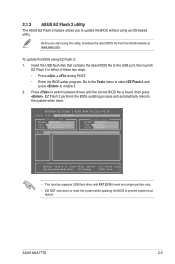
Insert the USB flash disk that contains the latest BIOS file to enable it. 2. To update the BIOS using EZ Flash 2: 1. EZ Flash 2 performs the BIOS updating process and automatically reboots the system when done. ASUS M4A77TD 2-3 Go to the Tools menu to select EZ Flash 2 and press to the USB port, then... launch EZ Flash 2 in either of these two ways: • Press + during POST. • Enter the BIOS setup program. Before you to update the BIOS without using an OS&#...
Insert the USB flash disk that contains the latest BIOS file to enable it. 2. To update the BIOS using EZ Flash 2: 1. EZ Flash 2 performs the BIOS updating process and automatically reboots the system when done. ASUS M4A77TD 2-3 Go to the Tools menu to select EZ Flash 2 and press to the USB port, then... launch EZ Flash 2 in either of these two ways: • Press + during POST. • Enter the BIOS setup program. Before you to update the BIOS without using an OS&#...
User Manual
Page 44
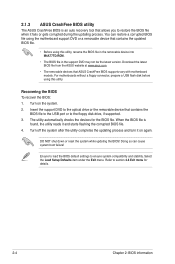
...updated BIOS file. • Before using this utility, rename the BIOS file in the removable device into M4A77TD.ROM. • The BIOS file in the support DVD may not be the latest version. The utility automatically checks the devices for details. 2-4 Chapter 2: BIOS ...BIOS! Recovering the BIOS To recover the BIOS: 1. Turn on again. When the BIOS file is an auto recovery tool that ASUS CrashFree BIOS supports vary with motherboard models. Ensure to load the BIOS default settings to the floppy disk drive, if supported. 3. 2.1.3 ASUS CrashFree BIOS utility The ASUS CrashFree BIOS ...
...updated BIOS file. • Before using this utility, rename the BIOS file in the removable device into M4A77TD.ROM. • The BIOS file in the support DVD may not be the latest version. The utility automatically checks the devices for details. 2-4 Chapter 2: BIOS ...BIOS! Recovering the BIOS To recover the BIOS: 1. Turn on again. When the BIOS file is an auto recovery tool that ASUS CrashFree BIOS supports vary with motherboard models. Ensure to load the BIOS default settings to the floppy disk drive, if supported. 3. 2.1.3 ASUS CrashFree BIOS utility The ASUS CrashFree BIOS ...
User Manual
Page 45
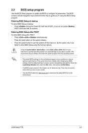
... down the system properly from a running operating system can cause damage to turn the system off then back on your data or system. Do this motherboard. ASUS M4A77TD 2-5 The BIOS screens include navigation keys and brief online help to guide you do not press , POST continues with its parameters. Select the Load Setup Defaults...
... down the system properly from a running operating system can cause damage to turn the system off then back on your data or system. Do this motherboard. ASUS M4A77TD 2-5 The BIOS screens include navigation keys and brief online help to guide you do not press , POST continues with its parameters. Select the Load Setup Defaults...

User Manual
Page 46
... of the navigation keys differ from one screen to configure system Time. Use the navigation keys to select a field. 2.2.1 BIOS menu screen Menu items Menu bar Configuration fields Main Advanced Power BIOS SETUP UTILITY Boot Tools Exit Main Settings System Time [19:34:30] System Date [Fri 07/31/2009] Primary IDE... of a menu screen are the navigation keys for special functions Exit For selecting the exit options and loading default settings. Use [+] or [-] to another. 2-6 Chapter 2: BIOS information
... of the navigation keys differ from one screen to configure system Time. Use the navigation keys to select a field. 2.2.1 BIOS menu screen Menu items Menu bar Configuration fields Main Advanced Power BIOS SETUP UTILITY Boot Tools Exit Main Settings System Time [19:34:30] System Date [Fri 07/31/2009] Primary IDE... of a menu screen are the navigation keys for special functions Exit For selecting the exit options and loading default settings. Use [+] or [-] to another. 2-6 Chapter 2: BIOS information
User Manual
Page 47
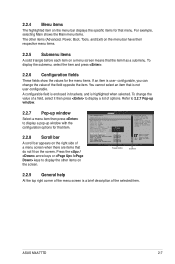
... a list of a menu screen when there are items that the item has a submenu. NOTE: If an invalid ratio is highlighted when selected. ASUS M4A77TD 2-7 To change the value of the selected item. A configurable field is enclosed in brackets, and is set in CMOS then actual and setpoint values...of the menu screen is user- For example, selecting Main shows the Main menu items. The other items on the right side of options. BIOS SETUP UTILITY Advanced CPU Configuration AGESA Version: 3.3.1.0 AMD Phenom(tm) II X4 945 Processor Revision: C2 Cache L1: 512KB Cache L2: 2048KB Cache...
... a list of a menu screen when there are items that the item has a submenu. NOTE: If an invalid ratio is highlighted when selected. ASUS M4A77TD 2-7 To change the value of the selected item. A configurable field is enclosed in brackets, and is set in CMOS then actual and setpoint values...of the menu screen is user- For example, selecting Main shows the Main menu items. The other items on the right side of options. BIOS SETUP UTILITY Advanced CPU Configuration AGESA Version: 3.3.1.0 AMD Phenom(tm) II X4 945 Processor Revision: C2 Cache L1: 512KB Cache L2: 2048KB Cache...

User Manual
Page 48
...submenu for information on the menu screen items and how to set the system date. 2.3.3 Primary IDE Master/Slave, SATA 1/2/3/4/5/6 While entering Setup, the BIOS automatically detects the presence of the appropriate IDE device type. Configuration options: [Not Installed] [Auto] [CDROM] [ARMD] This item only appears in... the system. 2.3 Main menu When you enter the BIOS Setup program, the Main menu screen appears, giving you an overview of IDE/SATA drive. Select a device item then press to [Auto] allows...
...submenu for information on the menu screen items and how to set the system date. 2.3.3 Primary IDE Master/Slave, SATA 1/2/3/4/5/6 While entering Setup, the BIOS automatically detects the presence of the appropriate IDE device type. Configuration options: [Not Installed] [Auto] [CDROM] [ARMD] This item only appears in... the system. 2.3 Main menu When you enter the BIOS Setup program, the Main menu screen appears, giving you an overview of IDE/SATA drive. Select a device item then press to [Auto] allows...

User Manual
Page 50
...Advanced menu items. Incorrect field values can cause the system to achieve desired CPU internal frequency. Main Advanced Advanced Settings Power BIOS SETUP UTILITY Boot Tools Exit JumperFree Configuration CPU Configuration Chipset Onboard Devices Configuration PCIPnP USB Configuration Adjust System Frequency/Voltage etc. ... the settings of the general system specifications. Configuration options: [Auto] [Manual] [Overclock Profile] [Test Mode] 2-10 Chapter 2: BIOS information 2.3.5 System Information This menu gives you to change the settings for the CPU and other system devices...
...Advanced menu items. Incorrect field values can cause the system to achieve desired CPU internal frequency. Main Advanced Advanced Settings Power BIOS SETUP UTILITY Boot Tools Exit JumperFree Configuration CPU Configuration Chipset Onboard Devices Configuration PCIPnP USB Configuration Adjust System Frequency/Voltage etc. ... the settings of the general system specifications. Configuration options: [Auto] [Manual] [Overclock Profile] [Test Mode] 2-10 Chapter 2: BIOS information 2.3.5 System Information This menu gives you to change the settings for the CPU and other system devices...

User Manual
Page 52
...] TWTR [Auto] Configuration options: [Auto] [4 CLK] ~ [7 CLK] TWRWR [Auto] Configuration options: [Auto] [3 CLK] ~ [10 CLK] TRDRD [Auto] Configuration options: [Auto] [3 CLK] ~ [10 CLK] 2-12 Chapter 2: BIOS information If this item is set to [Auto], the DRAM speed depends on the...
...] TWTR [Auto] Configuration options: [Auto] [4 CLK] ~ [7 CLK] TWRWR [Auto] Configuration options: [Auto] [3 CLK] ~ [10 CLK] TRDRD [Auto] Configuration options: [Auto] [3 CLK] ~ [10 CLK] 2-12 Chapter 2: BIOS information If this item is set to [Auto], the DRAM speed depends on the...


