K8S-MX English User Manual E1884
Page 1
Motherboard K8S-MX User Guide
Motherboard K8S-MX User Guide
K8S-MX English User Manual E1884
Page 3
... vi Safety information vii About this guide viii Conventions used in this guide viii Typography viii K8S-MX specifications summary ix Chapter 1: Product introduction 1.1 Welcome 1-2 1.2 Package contents 1-2 1.3 Special features 1-3 1.3.1 Product Highlights 1-3 1.3.2 Unique ASUS features 1-4 1.4 Before you proceed 1-5 1.5 Motherboard overview 1-6 1.5.1 Motherboard layout 1-6 1.5.2 Placement direction 1-7 1.5.3 Screw holes 1-7 1.6 Central Processing Unit (CPU 1-8 1.6.1 Overview 1-8 1.6.2 Installing the CPU 1-9 1.7 System memory...
... vi Safety information vii About this guide viii Conventions used in this guide viii Typography viii K8S-MX specifications summary ix Chapter 1: Product introduction 1.1 Welcome 1-2 1.2 Package contents 1-2 1.3 Special features 1-3 1.3.1 Product Highlights 1-3 1.3.2 Unique ASUS features 1-4 1.4 Before you proceed 1-5 1.5 Motherboard overview 1-6 1.5.1 Motherboard layout 1-6 1.5.2 Placement direction 1-7 1.5.3 Screw holes 1-7 1.6 Central Processing Unit (CPU 1-8 1.6.1 Overview 1-8 1.6.2 Installing the CPU 1-9 1.7 System memory...

K8S-MX English User Manual E1884
Page 7
Contact a qualified service technician or your area. Operation safety • Before installing the motherboard and adding devices on a stable surface. • If you encounter technical problems with the package. • Before using an adpater or extension cord. If possible, ... from the existing system before the signal cables are unplugged. • Seek professional assistance before using the product, make sure all power cables from the motherboard, ensure that came with the product, contact a qualified service technician or your retailer.
Contact a qualified service technician or your area. Operation safety • Before installing the motherboard and adding devices on a stable surface. • If you encounter technical problems with the package. • Before using an adpater or extension cord. If possible, ... from the existing system before the signal cables are unplugged. • Seek professional assistance before using the product, make sure all power cables from the motherboard, ensure that came with the product, contact a qualified service technician or your retailer.

K8S-MX English User Manual E1884
Page 11
Product introduction It includes brief descriptions of the motherboard components, and illustrations of the motherboard. Chapter 1 This chapter describes the features of the layout, jumper settings, and connectors.
Product introduction It includes brief descriptions of the motherboard components, and illustrations of the motherboard. Chapter 1 This chapter describes the features of the layout, jumper settings, and connectors.
K8S-MX English User Manual E1884
Page 12
... a host of new features and latest technologies making it , check the items in your package with the list below. 1.2 Package contents Check your motherboard package for the following items. ASUS K8S-MX motherboard ASUS motherboard support CD 1 x Ultra DMA 133/100/66 cables 2 x Serial ATA cables 1 x Floppy disk cable I/O shield User guide If any of the AMD...
... a host of new features and latest technologies making it , check the items in your package with the list below. 1.2 Package contents Check your motherboard package for the following items. ASUS K8S-MX motherboard ASUS motherboard support CD 1 x Ultra DMA 133/100/66 cables 2 x Serial ATA cables 1 x Floppy disk cable I/O shield User guide If any of the AMD...
K8S-MX English User Manual E1884
Page 13
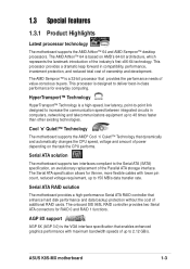
ASUS K8S-MX motherboard 1-3 This processor is designed to 48 times faster than other existing technologies. HyperTransport™ Technology HyperTransport™ Technology is the VGA interface specification that ... RAID controller provides two Serial ATA connectors for thinner, more flexible cables with maximum bandwidth speeds of additional RAID cards. Serial ATA RAID solution The motherboard provides a high-performance Serial ATA RAID controller that provides the performance needs of the industry's first x86-64 technology. This processor provides a dramatic leap...
ASUS K8S-MX motherboard 1-3 This processor is designed to 48 times faster than other existing technologies. HyperTransport™ Technology HyperTransport™ Technology is the VGA interface specification that ... RAID controller provides two Serial ATA connectors for thinner, more flexible cables with maximum bandwidth speeds of additional RAID cards. Serial ATA RAID solution The motherboard provides a high-performance Serial ATA RAID controller that provides the performance needs of the industry's first x86-64 technology. This processor provides a dramatic leap...

K8S-MX English User Manual E1884
Page 14
... and data are corrupted. ASUS MyLogo™ This new feature present in case the system hangs due to overclocking. eliminates the need to use a DOS-based utility or boot from a floppy disk. See page 2-5. 1-4 Chapter 1: Product introduction S/PDIF out The motherboard's S/PDIF out function turns...(USB 2.0) specification, extending the connection speed from 12 Mbps on USB 1.1 to a fast 480Mbps on USB 2.0. 6-Channel Audio solution The motherboard uses an onboard audio CODEC that lets you enjoy high-quality 6-channel audio without having to buy a replacement ROM chip. Simply shut down ...
... and data are corrupted. ASUS MyLogo™ This new feature present in case the system hangs due to overclocking. eliminates the need to use a DOS-based utility or boot from a floppy disk. See page 2-5. 1-4 Chapter 1: Product introduction S/PDIF out The motherboard's S/PDIF out function turns...(USB 2.0) specification, extending the connection speed from 12 Mbps on USB 1.1 to a fast 480Mbps on USB 2.0. 6-Channel Audio solution The motherboard uses an onboard audio CODEC that lets you enjoy high-quality 6-channel audio without having to buy a replacement ROM chip. Simply shut down ...
K8S-MX English User Manual E1884
Page 15
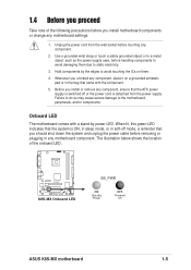
...Whenever you uninstall any component, place it on them due to avoid touching the ICs on a grounded antistatic pad or in any motherboard component. When lit, this green LED indicates that came with a stand-by the edges to static electricity. 3. Use a ...supply case, before touching any motherboard settings. 1. Unplug the power cord from the power supply. 1.4 Before you proceed Take note of the onboard LED. ® K8S-MX K8S-MX Onboard LED SB_PWR ON Standby Power OFF Powered Off ASUS K8S-MX motherboard 1-5 Onboard LED The motherboard comes with the component. 5....
...Whenever you uninstall any component, place it on them due to avoid touching the ICs on a grounded antistatic pad or in any motherboard component. When lit, this green LED indicates that came with a stand-by the edges to static electricity. 3. Use a ...supply case, before touching any motherboard settings. 1. Unplug the power cord from the power supply. 1.4 Before you proceed Take note of the onboard LED. ® K8S-MX K8S-MX Onboard LED SB_PWR ON Standby Power OFF Powered Off ASUS K8S-MX motherboard 1-5 Onboard LED The motherboard comes with the component. 5....
K8S-MX English User Manual E1884
Page 16
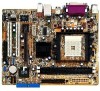
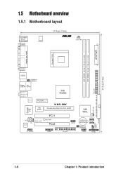
ATXPWR 1.5 Motherboard overview 1.5.1 Motherboard layout PS/2KBMS T: Mouse B: Keyboard COM1 ATX12V 19.3cm (7.6in) ® CPU_FAN DDR DIMM1 (64 bit, 184-pin module) DDR DIMM2 (64 bit, 184-pin ... PORT Socket 754 VGA USB12 USBPW34 USBPW12 Bottom: Top: USB34 RJ-45 Top:Line In Center:Line Out Below:Mic In SIS 760GX RTL8201CL PCIEX1_1 K8S-MX 4M BIOS Accelerated Graphics Port (AGP) Super I/O AUX AD1888 SPDIF_OUT CD PCI1 SB_PWR PCI2 USB78 FP_AUDIO GAME FLOPPY SIS 965L CR2032 3V Lithium Cell CMOS...
ATXPWR 1.5 Motherboard overview 1.5.1 Motherboard layout PS/2KBMS T: Mouse B: Keyboard COM1 ATX12V 19.3cm (7.6in) ® CPU_FAN DDR DIMM1 (64 bit, 184-pin module) DDR DIMM2 (64 bit, 184-pin ... PORT Socket 754 VGA USB12 USBPW34 USBPW12 Bottom: Top: USB34 RJ-45 Top:Line In Center:Line Out Below:Mic In SIS 760GX RTL8201CL PCIEX1_1 K8S-MX 4M BIOS Accelerated Graphics Port (AGP) Super I/O AUX AD1888 SPDIF_OUT CD PCI1 SB_PWR PCI2 USB78 FP_AUDIO GAME FLOPPY SIS 965L CR2032 3V Lithium Cell CMOS...
K8S-MX English User Manual E1884
Page 17
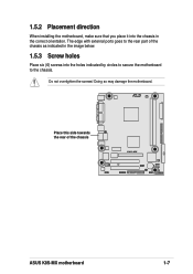
R Place this side towards the rear of the chassis as indicated in the image below. 1.5.3 Screw holes Place six (6) screws into the chassis in the correct orientation. The edge with external ports goes to the chassis. Doing so may damage the motherboard. Do not overtighten the screws! 1.5.2 Placement direction When installing the motherboard, make sure that you place it into the holes indicated by circles to secure the motherboard to the rear part of the chassis K8S-MX ASUS K8S-MX motherboard 1-7
R Place this side towards the rear of the chassis as indicated in the image below. 1.5.3 Screw holes Place six (6) screws into the chassis in the correct orientation. The edge with external ports goes to the chassis. Doing so may damage the motherboard. Do not overtighten the screws! 1.5.2 Placement direction When installing the motherboard, make sure that you place it into the holes indicated by circles to secure the motherboard to the rear part of the chassis K8S-MX ASUS K8S-MX motherboard 1-7
K8S-MX English User Manual E1884
Page 18
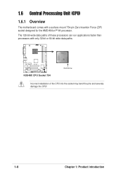
1.6 Central Processing Unit (CPU) 1.6.1 Overview The motherboard comes with only 32-bit or 64-bit wide data paths. ® K8S-MX K8S-MX CPU Socket 754 Gold Arrow Incorrect installation of these processors can run applications faster than processors with a surface mount 754-pin Zero Insertion Force (ZIF) socket designed for the AMD Athlon™ 64 processor. The 128-bit-wide data paths of the CPU into the socket may bend the pins and severely damage the CPU! 1-8 Chapter 1: Product introduction
1.6 Central Processing Unit (CPU) 1.6.1 Overview The motherboard comes with only 32-bit or 64-bit wide data paths. ® K8S-MX K8S-MX CPU Socket 754 Gold Arrow Incorrect installation of these processors can run applications faster than processors with a surface mount 754-pin Zero Insertion Force (ZIF) socket designed for the AMD Athlon™ 64 processor. The 128-bit-wide data paths of the CPU into the socket may bend the pins and severely damage the CPU! 1-8 Chapter 1: Product introduction
K8S-MX English User Manual E1884
Page 19
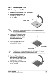
... CPU fits only in place. When the CPU is locked. 6. 1.6.2 Installing the CPU Follow these steps to prevent bending the pins and damaging the CPU! 5. ASUS K8S-MX motherboard 1-9 Unlock the socket by pressing the lever sideways, then lift it is in completely. 3. The lever clicks on the...
... CPU fits only in place. When the CPU is locked. 6. 1.6.2 Installing the CPU Follow these steps to prevent bending the pins and damaging the CPU! 5. ASUS K8S-MX motherboard 1-9 Unlock the socket by pressing the lever sideways, then lift it is in completely. 3. The lever clicks on the...

K8S-MX English User Manual E1884
Page 20
...section. See Qualified Vendors List on page 1-12. 1-10 Chapter 1: Product introduction Failure to do so may cause severe damage to both the motherboard and the components. • When installing long AGP cards, it is recommended to unplug the power supply before adding or removing DIMMs or .... For optimum compatibility, obtain memory modules from qualified vendors. Use any of the DDR DIMM sockets. ® DIMM1 DIMM2 104 Pins 80 Pins K8S-MX K8S-MX 184-pin DDR DIMM sockets • Make sure to install the memory modules first. See Qualified Vendors List on page 1-12. • Stacked...
...section. See Qualified Vendors List on page 1-12. 1-10 Chapter 1: Product introduction Failure to do so may cause severe damage to both the motherboard and the components. • When installing long AGP cards, it is recommended to unplug the power supply before adding or removing DIMMs or .... For optimum compatibility, obtain memory modules from qualified vendors. Use any of the DDR DIMM sockets. ® DIMM1 DIMM2 104 Pins 80 Pins K8S-MX K8S-MX 184-pin DDR DIMM sockets • Make sure to install the memory modules first. See Qualified Vendors List on page 1-12. • Stacked...

K8S-MX English User Manual E1884
Page 21
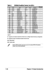
...-TCCC K4H560838F-TCCC K4H560838F-TCB3 K4H5608838F-TCB3 W942508CH-5 W942508CH-6 W942508BH-6 W942508CH-5 DD2508AKTA-5C DD2508AMTA K4H560838F-TCCC V58C2256804SAT5B DIMM support AB (Continued on the next page) ASUS K8S-MX motherboard 1-11 Table 1 Recommended memory configurations Number of DIMMs DIMM1 1 Single Side 1 - 1 Double Side 1 - 2 Single Side 2 Single Side 2 Double Side 2 Double Side DIMM Slot DIMM2...
...-TCCC K4H560838F-TCCC K4H560838F-TCB3 K4H5608838F-TCB3 W942508CH-5 W942508CH-6 W942508BH-6 W942508CH-5 DD2508AKTA-5C DD2508AMTA K4H560838F-TCCC V58C2256804SAT5B DIMM support AB (Continued on the next page) ASUS K8S-MX motherboard 1-11 Table 1 Recommended memory configurations Number of DIMMs DIMM1 1 Single Side 1 - 1 Double Side 1 - 2 Single Side 2 Single Side 2 Double Side 2 Double Side DIMM Slot DIMM2...
K8S-MX English User Manual E1884
Page 22
supports one pair of modules inserted into either slot, in a Single-channel memory configuration. Double-sided Visit the ASUS website (www.asus.com) for the latest DDR 400 Qualified Vendor List for this motherboard. 1-12 Chapter 1: Product introduction Single-sided DS - B - supports one module inserted into both slots. SS - Table 2 DDR400 Qualified Vendor List...
supports one pair of modules inserted into either slot, in a Single-channel memory configuration. Double-sided Visit the ASUS website (www.asus.com) for the latest DDR 400 Qualified Vendor List for this motherboard. 1-12 Chapter 1: Product introduction Single-sided DS - B - supports one module inserted into both slots. SS - Table 2 DDR400 Qualified Vendor List...

K8S-MX English User Manual E1884
Page 23
... notch on the DIMM matches the break on the system and change the necessary BIOS settings, if any. See Chapter 2 for ISA or PCI devices. ASUS K8S-MX motherboard 1-13 Unlock a DIMM socket by pressing the retaining clips outward. 2. Install the drivers and/or software applications for the expansion card according to the tables...
... notch on the DIMM matches the break on the system and change the necessary BIOS settings, if any. See Chapter 2 for ISA or PCI devices. ASUS K8S-MX motherboard 1-13 Unlock a DIMM socket by pressing the retaining clips outward. 2. Install the drivers and/or software applications for the expansion card according to the tables...

K8S-MX English User Manual E1884
Page 24
... support PCI cards such as a LAN card, SCSI card, USB card, and other cards that comply with PCI specifications. 1.8.4 PCI Express x1 slot This motherboard supports PCI Express x1 network cards, SCSI cards and other cards that the cards do not need IRQ assignments. shared - - - When using PCI cards ...on the PCI Express x1 slot. 1-14 Chapter 1: Product introduction 1.8.2 IRQ assignments for this motherboard PCI slot 1 PCI slot 2 LAN AGP slot VGA slot INT A shared - - - - shared shared INT D - - shared - -
... support PCI cards such as a LAN card, SCSI card, USB card, and other cards that comply with PCI specifications. 1.8.4 PCI Express x1 slot This motherboard supports PCI Express x1 network cards, SCSI cards and other cards that the cards do not need IRQ assignments. shared - - - When using PCI cards ...on the PCI Express x1 slot. 1-14 Chapter 1: Product introduction 1.8.2 IRQ assignments for this motherboard PCI slot 1 PCI slot 2 LAN AGP slot VGA slot INT A shared - - - - shared shared INT D - - shared - -

K8S-MX English User Manual E1884
Page 25
When you buy an AGP card, make sure that they fit the AGP slot on the motherboard. 1.8.5 AGP slot The Accelerated Graphics Port (AGP) slot supports AGP 8X/4X (+1.5V) cards. ASUS K8S-MX motherboard 1-15 Install only +1.5V AGP cards. ® K8S-MX Keyed for 1.5v K8S-MX Accelerated Graphics Port (AGP) If installing the ATi 9500 or 9700 Pro Series VGA cards, use only the card version PN xxx-xxxxx-30 or later, for one with +1.5V specification. Note the notches on the card golden fingers to ensure that you ask for optimum performance and overclocking stability.
When you buy an AGP card, make sure that they fit the AGP slot on the motherboard. 1.8.5 AGP slot The Accelerated Graphics Port (AGP) slot supports AGP 8X/4X (+1.5V) cards. ASUS K8S-MX motherboard 1-15 Install only +1.5V AGP cards. ® K8S-MX Keyed for 1.5v K8S-MX Accelerated Graphics Port (AGP) If installing the ATi 9500 or 9700 Pro Series VGA cards, use only the card version PN xxx-xxxxx-30 or later, for one with +1.5V specification. Note the notches on the card golden fingers to ensure that you ask for optimum performance and overclocking stability.

K8S-MX English User Manual E1884
Page 27
... up the computer from S1 sleep mode (CPU stopped, DRAM refreshed, system running in reduced power mode). ® USBPW34 USBPW12 12 23 K8S-MX +5V +5VSB (Default) USBPW78 USBPW56 12 23 K8S-MX USB device wake-up +5V (Default) +5VSB • The USB device wake-up . • The total current consumed must NOT exceed... sleep mode. 2. Otherwise, the system would not power up feature requires a power supply that can provide 500mA on the +5VSB lead for each USB port. ASUS K8S-MX motherboard 1-17
... up the computer from S1 sleep mode (CPU stopped, DRAM refreshed, system running in reduced power mode). ® USBPW34 USBPW12 12 23 K8S-MX +5V +5VSB (Default) USBPW78 USBPW56 12 23 K8S-MX USB device wake-up +5V (Default) +5VSB • The USB device wake-up . • The total current consumed must NOT exceed... sleep mode. 2. Otherwise, the system would not power up feature requires a power supply that can provide 500mA on the +5VSB lead for each USB port. ASUS K8S-MX motherboard 1-17

K8S-MX English User Manual E1884
Page 28
... in the following table. This purple connector is for a PS/2 mouse. 2. Line In jack. USB 2.0 ports 3 and 4. 1.10 Connectors This section describes and illustrates the motherboard rear panel and internal connectors. 1.10.1 Rear panel connectors 1 2 3 4 5 6 11 10 9 8 7 1. This Line In (light blue) jack connects a tape player or other devices. 3. This green...
... in the following table. This purple connector is for a PS/2 mouse. 2. Line In jack. USB 2.0 ports 3 and 4. 1.10 Connectors This section describes and illustrates the motherboard rear panel and internal connectors. 1.10.1 Rear panel connectors 1 2 3 4 5 6 11 10 9 8 7 1. This Line In (light blue) jack connects a tape player or other devices. 3. This green...


