K8S-MX English User Manual E1884
Page 1
Motherboard K8S-MX User Guide
Motherboard K8S-MX User Guide
K8S-MX English User Manual E1884
Page 3
... vi Safety information vii About this guide viii Conventions used in this guide viii Typography viii K8S-MX specifications summary ix Chapter 1: Product introduction 1.1 Welcome 1-2 1.2 Package contents 1-2 1.3 Special features 1-3 1.3.1 Product Highlights 1-3 1.3.2 Unique ASUS features 1-4 1.4 Before you proceed 1-5 1.5 Motherboard overview 1-6 1.5.1 Motherboard layout 1-6 1.5.2 Placement direction 1-7 1.5.3 Screw holes 1-7 1.6 Central Processing Unit (CPU 1-8 1.6.1 Overview 1-8 1.6.2 Installing the CPU 1-9 1.7 System memory...
... vi Safety information vii About this guide viii Conventions used in this guide viii Typography viii K8S-MX specifications summary ix Chapter 1: Product introduction 1.1 Welcome 1-2 1.2 Package contents 1-2 1.3 Special features 1-3 1.3.1 Product Highlights 1-3 1.3.2 Unique ASUS features 1-4 1.4 Before you proceed 1-5 1.5 Motherboard overview 1-6 1.5.1 Motherboard layout 1-6 1.5.2 Placement direction 1-7 1.5.3 Screw holes 1-7 1.6 Central Processing Unit (CPU 1-8 1.6.1 Overview 1-8 1.6.2 Installing the CPU 1-9 1.7 System memory...

K8S-MX English User Manual E1884
Page 7
Contact a qualified service technician or your area. Operation safety • Before installing the motherboard and adding devices on it, carefully read all the manuals that came with the product, contact a qualified service technician or your dealer immediately....your retailer. Do not place the product in your retailer. If you add a device. • Before connecting or removing signal cables from the motherboard, ensure that the power cables for the devices are unplugged before the signal cables are not damaged. Safety information Electrical safety • To prevent ...
Contact a qualified service technician or your area. Operation safety • Before installing the motherboard and adding devices on it, carefully read all the manuals that came with the product, contact a qualified service technician or your dealer immediately....your retailer. Do not place the product in your retailer. If you add a device. • Before connecting or removing signal cables from the motherboard, ensure that the power cables for the devices are unplugged before the signal cables are not damaged. Safety information Electrical safety • To prevent ...

K8S-MX English User Manual E1884
Page 11
Product introduction Chapter 1 This chapter describes the features of the layout, jumper settings, and connectors. It includes brief descriptions of the motherboard components, and illustrations of the motherboard.
Product introduction Chapter 1 This chapter describes the features of the layout, jumper settings, and connectors. It includes brief descriptions of the motherboard components, and illustrations of the motherboard.
K8S-MX English User Manual E1884
Page 12
...latest technologies making it , check the items in the world of the above items is damaged or missing, contact your motherboard package for the following items. ASUS K8S-MX motherboard ASUS motherboard support CD 1 x Ultra DMA 133/100/66 cables 2 x Serial ATA cables 1 x Floppy disk cable I/O ...shield User guide If any of power computing! Thank you start installing the motherboard, and hardware devices on it another standout in ...
...latest technologies making it , check the items in the world of the above items is damaged or missing, contact your motherboard package for the following items. ASUS K8S-MX motherboard ASUS motherboard support CD 1 x Ultra DMA 133/100/66 cables 2 x Serial ATA cables 1 x Floppy disk cable I/O ...shield User guide If any of power computing! Thank you start installing the motherboard, and hardware devices on it another standout in ...
K8S-MX English User Manual E1884
Page 13
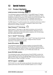
...174; Cool 'n' Quiet!™ Technology that provides the performance needs of the Parallel ATA storage interface. ASUS K8S-MX motherboard 1-3 Serial ATA RAID solution The motherboard provides a high-performance Serial ATA RAID controller that enables enhanced graphics performance with lower pin count, reduced...the industry's first x86-64 technology. This processor is based on the task the CPU performs. Serial ATA solution The motherboard supports two interfaces compliant to the Serial ATA (SATA) specification, an evolutionary replacement of value-conscious buyers. This processor ...
...174; Cool 'n' Quiet!™ Technology that provides the performance needs of the Parallel ATA storage interface. ASUS K8S-MX motherboard 1-3 Serial ATA RAID solution The motherboard provides a high-performance Serial ATA RAID controller that enables enhanced graphics performance with lower pin count, reduced...the industry's first x86-64 technology. This processor is based on the task the CPU performs. Serial ATA solution The motherboard supports two interfaces compliant to the Serial ATA (SATA) specification, an evolutionary replacement of value-conscious buyers. This processor ...

K8S-MX English User Manual E1884
Page 14
..., and BIOS automatically restores the CPU previous setting for each parameter. C.P.R. (CPU Parameter Recall) The C.P.R. ASUS MyLogo™ This new feature present in the motherboard allows you to personalize and add style to your computer into a high-end entertainment system with customizable boot ...USB 2.0) specification, extending the connection speed from 12 Mbps on USB 1.1 to a fast 480Mbps on USB 2.0. 6-Channel Audio solution The motherboard uses an onboard audio CODEC that lets you enjoy high-quality 6-channel audio without having to buy a replacement ROM chip. This protection ...
..., and BIOS automatically restores the CPU previous setting for each parameter. C.P.R. (CPU Parameter Recall) The C.P.R. ASUS MyLogo™ This new feature present in the motherboard allows you to personalize and add style to your computer into a high-end entertainment system with customizable boot ...USB 2.0) specification, extending the connection speed from 12 Mbps on USB 1.1 to a fast 480Mbps on USB 2.0. 6-Channel Audio solution The motherboard uses an onboard audio CODEC that lets you enjoy high-quality 6-channel audio without having to buy a replacement ROM chip. This protection ...
K8S-MX English User Manual E1884
Page 15
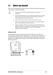
...system is ON, in sleep mode, or in the bag that came with the component. 5. Whenever you uninstall any motherboard settings. 1. Onboard LED The motherboard comes with a stand-by the edges to avoid touching the ICs on a grounded antistatic pad or in soft-off mode.... 3. Hold components by power LED. 1.4 Before you proceed Take note of the onboard LED. ® K8S-MX K8S-MX Onboard LED SB_PWR ON Standby Power OFF Powered Off ASUS K8S-MX motherboard 1-5 The illustration below shows the location of the following precautions before touching any component. 2. Unplug the power ...
...system is ON, in sleep mode, or in the bag that came with the component. 5. Whenever you uninstall any motherboard settings. 1. Onboard LED The motherboard comes with a stand-by the edges to avoid touching the ICs on a grounded antistatic pad or in soft-off mode.... 3. Hold components by power LED. 1.4 Before you proceed Take note of the onboard LED. ® K8S-MX K8S-MX Onboard LED SB_PWR ON Standby Power OFF Powered Off ASUS K8S-MX motherboard 1-5 The illustration below shows the location of the following precautions before touching any component. 2. Unplug the power ...
K8S-MX English User Manual E1884
Page 16
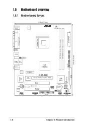
ATXPWR 1.5 Motherboard overview 1.5.1 Motherboard layout PS/2KBMS T: Mouse B: Keyboard COM1 ATX12V 19.3cm (7.6in) ® CPU_FAN DDR DIMM1 (64 bit, 184-pin module) DDR DIMM2 (64 bit, 184-pin ... PORT Socket 754 VGA USB12 USBPW34 USBPW12 Bottom: Top: USB34 RJ-45 Top:Line In Center:Line Out Below:Mic In SIS 760GX RTL8201CL PCIEX1_1 K8S-MX 4M BIOS Accelerated Graphics Port (AGP) Super I/O AUX AD1888 SPDIF_OUT CD PCI1 SB_PWR PCI2 USB78 FP_AUDIO GAME FLOPPY SIS 965L CR2032 3V Lithium Cell CMOS...
ATXPWR 1.5 Motherboard overview 1.5.1 Motherboard layout PS/2KBMS T: Mouse B: Keyboard COM1 ATX12V 19.3cm (7.6in) ® CPU_FAN DDR DIMM1 (64 bit, 184-pin module) DDR DIMM2 (64 bit, 184-pin ... PORT Socket 754 VGA USB12 USBPW34 USBPW12 Bottom: Top: USB34 RJ-45 Top:Line In Center:Line Out Below:Mic In SIS 760GX RTL8201CL PCIEX1_1 K8S-MX 4M BIOS Accelerated Graphics Port (AGP) Super I/O AUX AD1888 SPDIF_OUT CD PCI1 SB_PWR PCI2 USB78 FP_AUDIO GAME FLOPPY SIS 965L CR2032 3V Lithium Cell CMOS...
K8S-MX English User Manual E1884
Page 17
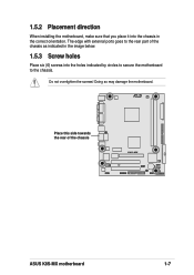
Doing so may damage the motherboard. R Place this side towards the rear of the chassis as indicated in the image below. 1.5.3 Screw holes Place six (6) screws into the chassis in the correct orientation. 1.5.2 Placement direction When installing the motherboard, make sure that you place it into the holes indicated by circles to secure the motherboard to the rear part of the chassis K8S-MX ASUS K8S-MX motherboard 1-7 The edge with external ports goes to the chassis. Do not overtighten the screws!
Doing so may damage the motherboard. R Place this side towards the rear of the chassis as indicated in the image below. 1.5.3 Screw holes Place six (6) screws into the chassis in the correct orientation. 1.5.2 Placement direction When installing the motherboard, make sure that you place it into the holes indicated by circles to secure the motherboard to the rear part of the chassis K8S-MX ASUS K8S-MX motherboard 1-7 The edge with external ports goes to the chassis. Do not overtighten the screws!
K8S-MX English User Manual E1884
Page 18
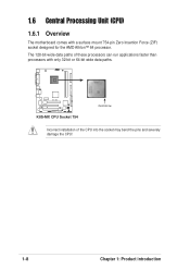
The 128-bit-wide data paths of the CPU into the socket may bend the pins and severely damage the CPU! 1-8 Chapter 1: Product introduction 1.6 Central Processing Unit (CPU) 1.6.1 Overview The motherboard comes with only 32-bit or 64-bit wide data paths. ® K8S-MX K8S-MX CPU Socket 754 Gold Arrow Incorrect installation of these processors can run applications faster than processors with a surface mount 754-pin Zero Insertion Force (ZIF) socket designed for the AMD Athlon™ 64 processor.
The 128-bit-wide data paths of the CPU into the socket may bend the pins and severely damage the CPU! 1-8 Chapter 1: Product introduction 1.6 Central Processing Unit (CPU) 1.6.1 Overview The motherboard comes with only 32-bit or 64-bit wide data paths. ® K8S-MX K8S-MX CPU Socket 754 Gold Arrow Incorrect installation of these processors can run applications faster than processors with a surface mount 754-pin Zero Insertion Force (ZIF) socket designed for the AMD Athlon™ 64 processor.
K8S-MX English User Manual E1884
Page 19
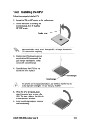
..., push down the socket lever to indicate that it up to prevent bending the pins and damaging the CPU! 5. The lever clicks on the motherboard. 2. Locate the 754-pin ZIF socket on the side tab to secure the CPU. Install specifically designed heatsink and fan assembly. Carefully insert the...176; angle. When the CPU is locked. 6. Position the CPU above the socket such that the socket lever is lifted up to install a CPU. 1. ASUS K8S-MX motherboard 1-9 Socket Lever Make sure that the CPU corner with the gold triangle matches the socket corner with a small triangle. 4.
..., push down the socket lever to indicate that it up to prevent bending the pins and damaging the CPU! 5. The lever clicks on the motherboard. 2. Locate the 754-pin ZIF socket on the side tab to secure the CPU. Install specifically designed heatsink and fan assembly. Carefully insert the...176; angle. When the CPU is locked. 6. Position the CPU above the socket such that the socket lever is lifted up to install a CPU. 1. ASUS K8S-MX motherboard 1-9 Socket Lever Make sure that the CPU corner with the gold triangle matches the socket corner with a small triangle. 4.

K8S-MX English User Manual E1884
Page 20
Use any of the DDR DIMM sockets. ® DIMM1 DIMM2 104 Pins 80 Pins K8S-MX K8S-MX 184-pin DDR DIMM sockets • Make sure to unplug the power supply before adding or removing DIMMs or other than 18 chips are not ... List on page 1-12. • Stacked RAM and DDR DIMM modules with the memory sockets. 1.7.2 Memory configurations You may cause severe damage to both the motherboard and the components. • When installing long AGP cards, it is recommended to do so may install 64MB, 128MB, 256MB, 512MB, and 1GB DDR DIMMs...
Use any of the DDR DIMM sockets. ® DIMM1 DIMM2 104 Pins 80 Pins K8S-MX K8S-MX 184-pin DDR DIMM sockets • Make sure to unplug the power supply before adding or removing DIMMs or other than 18 chips are not ... List on page 1-12. • Stacked RAM and DDR DIMM modules with the memory sockets. 1.7.2 Memory configurations You may cause severe damage to both the motherboard and the components. • When installing long AGP cards, it is recommended to do so may install 64MB, 128MB, 256MB, 512MB, and 1GB DDR DIMMs...

K8S-MX English User Manual E1884
Page 21
...-TCCC K4H560838F-TCCC K4H560838F-TCB3 K4H5608838F-TCB3 W942508CH-5 W942508CH-6 W942508BH-6 W942508CH-5 DD2508AKTA-5C DD2508AMTA K4H560838F-TCCC V58C2256804SAT5B DIMM support AB (Continued on the next page) ASUS K8S-MX motherboard 1-11 Table 1 Recommended memory configurations Number of DIMMs DIMM1 1 Single Side 1 - 1 Double Side 1 - 2 Single Side 2 Single Side 2 Double Side 2 Double Side DIMM Slot DIMM2...
...-TCCC K4H560838F-TCCC K4H560838F-TCB3 K4H5608838F-TCB3 W942508CH-5 W942508CH-6 W942508BH-6 W942508CH-5 DD2508AKTA-5C DD2508AMTA K4H560838F-TCCC V58C2256804SAT5B DIMM support AB (Continued on the next page) ASUS K8S-MX motherboard 1-11 Table 1 Recommended memory configurations Number of DIMMs DIMM1 1 Single Side 1 - 1 Double Side 1 - 2 Single Side 2 Single Side 2 Double Side 2 Double Side DIMM Slot DIMM2...
K8S-MX English User Manual E1884
Page 22
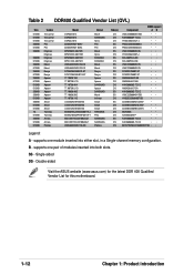
... slot, in a Single-channel memory configuration. B - supports one module inserted into both slots. SS - Double-sided Visit the ASUS website (www.asus.com) for the latest DDR 400 Qualified Vendor List for this motherboard. 1-12 Chapter 1: Product introduction Table 2 DDR400 Qualified Vendor List (QVL) Size 512MB 512MB 512MB 256MB 512MB 256MB 256MB 512MB...
... slot, in a Single-channel memory configuration. B - supports one module inserted into both slots. SS - Double-sided Visit the ASUS website (www.asus.com) for the latest DDR 400 Qualified Vendor List for this motherboard. 1-12 Chapter 1: Product introduction Table 2 DDR400 Qualified Vendor List (QVL) Size 512MB 512MB 512MB 256MB 512MB 256MB 256MB 512MB...

K8S-MX English User Manual E1884
Page 23
Install an expansion card following the instructions that came with a notch so that the notch on the DIMM matches the break on the socket. 3. ASUS K8S-MX motherboard 1-13 See Chapter 2 for the expansion card according to the tables next page. 4. Refer to the card documentation. 1.8.1 Standard interrupt assignments IRQ Priority Standard Function 0 1 ...
Install an expansion card following the instructions that came with a notch so that the notch on the DIMM matches the break on the socket. 3. ASUS K8S-MX motherboard 1-13 See Chapter 2 for the expansion card according to the tables next page. 4. Refer to the card documentation. 1.8.1 Standard interrupt assignments IRQ Priority Standard Function 0 1 ...

K8S-MX English User Manual E1884
Page 24
...slots support PCI cards such as a LAN card, SCSI card, USB card, and other cards that comply with PCI specifications. 1.8.4 PCI Express x1 slot This motherboard supports PCI Express x1 network cards, SCSI cards and other cards that the cards do not need IRQ assignments. shared - - - The figure shows a ... specifications. INT C - - - When using PCI cards on the PCI Express x1 slot. 1-14 Chapter 1: Product introduction shared shared INT D - - 1.8.2 IRQ assignments for this motherboard PCI slot 1 PCI slot 2 LAN AGP slot VGA slot INT A shared - - - - INT B - shared - -
...slots support PCI cards such as a LAN card, SCSI card, USB card, and other cards that comply with PCI specifications. 1.8.4 PCI Express x1 slot This motherboard supports PCI Express x1 network cards, SCSI cards and other cards that the cards do not need IRQ assignments. shared - - - The figure shows a ... specifications. INT C - - - When using PCI cards on the PCI Express x1 slot. 1-14 Chapter 1: Product introduction shared shared INT D - - 1.8.2 IRQ assignments for this motherboard PCI slot 1 PCI slot 2 LAN AGP slot VGA slot INT A shared - - - - INT B - shared - -

K8S-MX English User Manual E1884
Page 25
1.8.5 AGP slot The Accelerated Graphics Port (AGP) slot supports AGP 8X/4X (+1.5V) cards. Install only +1.5V AGP cards. ® K8S-MX Keyed for 1.5v K8S-MX Accelerated Graphics Port (AGP) If installing the ATi 9500 or 9700 Pro Series VGA cards, use only the card version PN xxx-xxxxx-30 or later, for one with +1.5V specification. ASUS K8S-MX motherboard 1-15 When you buy an AGP card, make sure that they fit the AGP slot on the card golden fingers to ensure that you ask for optimum performance and overclocking stability. Note the notches on the motherboard.
1.8.5 AGP slot The Accelerated Graphics Port (AGP) slot supports AGP 8X/4X (+1.5V) cards. Install only +1.5V AGP cards. ® K8S-MX Keyed for 1.5v K8S-MX Accelerated Graphics Port (AGP) If installing the ATi 9500 or 9700 Pro Series VGA cards, use only the card version PN xxx-xxxxx-30 or later, for one with +1.5V specification. ASUS K8S-MX motherboard 1-15 When you buy an AGP card, make sure that they fit the AGP slot on the card golden fingers to ensure that you ask for optimum performance and overclocking stability. Note the notches on the motherboard.

K8S-MX English User Manual E1884
Page 27
... 12 23 K8S-MX +5V +5VSB (Default) USBPW78 USBPW56 12 23 K8S-MX USB device wake-up +5V (Default) +5VSB • The USB device wake-up . • The total current consumed must NOT exceed the power supply capability (+5VSB) whether under normal condition or in low power mode) using the connected USB devices. ASUS K8S-MX motherboard 1-17
... 12 23 K8S-MX +5V +5VSB (Default) USBPW78 USBPW56 12 23 K8S-MX USB device wake-up +5V (Default) +5VSB • The USB device wake-up . • The total current consumed must NOT exceed the power supply capability (+5VSB) whether under normal condition or in low power mode) using the connected USB devices. ASUS K8S-MX motherboard 1-17

K8S-MX English User Manual E1884
Page 28
.... 6. USB 2.0 ports 1 and 2. This port connects to the table below for a PS/2 keyboard. 1-18 Chapter 1: Product introduction 1.10 Connectors This section describes and illustrates the motherboard rear panel and internal connectors. 1.10.1 Rear panel connectors 1 2 3 4 5 6 11 10 9 8 7 1. This port allows connection to a Local Area Network (LAN) through a network hub. Microphone jack...
.... 6. USB 2.0 ports 1 and 2. This port connects to the table below for a PS/2 keyboard. 1-18 Chapter 1: Product introduction 1.10 Connectors This section describes and illustrates the motherboard rear panel and internal connectors. 1.10.1 Rear panel connectors 1 2 3 4 5 6 11 10 9 8 7 1. This port allows connection to a Local Area Network (LAN) through a network hub. Microphone jack...


