K8S-MX English User Manual E1884
Page 12
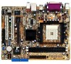
... on it another standout in your package with the list below. 1.2 Package contents Check your motherboard package for the following items. ASUS K8S-MX motherboard ASUS motherboard support CD 1 x Ultra DMA 133/100/66 cables 2 x Serial ATA cables 1 x Floppy disk cable I/O shield User... introduction Thank you for an effective desktop platform solution. Before you ahead in the world of ASUS quality motherboards! Supporting up to set a new benchmark for buying the ASUS® K8S-MX motherboard! 1.1 Welcome! The motherboard delivers a host of new features and latest technologies making it...
... on it another standout in your package with the list below. 1.2 Package contents Check your motherboard package for the following items. ASUS K8S-MX motherboard ASUS motherboard support CD 1 x Ultra DMA 133/100/66 cables 2 x Serial ATA cables 1 x Floppy disk cable I/O shield User... introduction Thank you for an effective desktop platform solution. Before you ahead in the world of ASUS quality motherboards! Supporting up to set a new benchmark for buying the ASUS® K8S-MX motherboard! 1.1 Welcome! The motherboard delivers a host of new features and latest technologies making it...
K8S-MX English User Manual E1884
Page 13
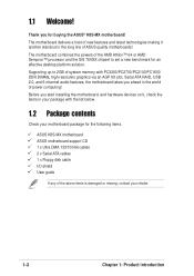
... ATA storage interface. Serial ATA RAID solution The motherboard provides a high-performance Serial ATA RAID controller that provides the performance needs of additional RAID cards. ASUS K8S-MX motherboard 1-3 The AMD Athlon™ 64 is a 32-bit processor that enhance hard disk performance and data backup protection without the cost of value-conscious...
... ATA storage interface. Serial ATA RAID solution The motherboard provides a high-performance Serial ATA RAID controller that provides the performance needs of additional RAID cards. ASUS K8S-MX motherboard 1-3 The AMD Athlon™ 64 is a 32-bit processor that enhance hard disk performance and data backup protection without the cost of value-conscious...
K8S-MX English User Manual E1884
Page 15
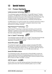
... in the bag that came with a stand-by power LED. 1.4 Before you proceed Take note of the onboard LED. ® K8S-MX K8S-MX Onboard LED SB_PWR ON Standby Power OFF Powered Off ASUS K8S-MX motherboard 1-5 The illustration below shows the location of the following precautions before touching any motherboard settings. 1. Unplug the power cord from...
... in the bag that came with a stand-by power LED. 1.4 Before you proceed Take note of the onboard LED. ® K8S-MX K8S-MX Onboard LED SB_PWR ON Standby Power OFF Powered Off ASUS K8S-MX motherboard 1-5 The illustration below shows the location of the following precautions before touching any motherboard settings. 1. Unplug the power cord from...
K8S-MX English User Manual E1884
Page 17
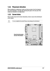
Do not overtighten the screws! R Place this side towards the rear of the chassis as indicated in the image below. 1.5.3 Screw holes Place six (6) screws into the chassis in the correct orientation. The edge with external ports goes to the chassis. Doing so may damage the motherboard. 1.5.2 Placement direction When installing the motherboard, make sure that you place it into the holes indicated by circles to secure the motherboard to the rear part of the chassis K8S-MX ASUS K8S-MX motherboard 1-7
Do not overtighten the screws! R Place this side towards the rear of the chassis as indicated in the image below. 1.5.3 Screw holes Place six (6) screws into the chassis in the correct orientation. The edge with external ports goes to the chassis. Doing so may damage the motherboard. 1.5.2 Placement direction When installing the motherboard, make sure that you place it into the holes indicated by circles to secure the motherboard to the rear part of the chassis K8S-MX ASUS K8S-MX motherboard 1-7
K8S-MX English User Manual E1884
Page 19
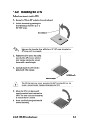
... is in completely. 3. 1.6.2 Installing the CPU Follow these steps to a 90°-100° angle. Small triangle Gold triangle The CPU fits only in place. ASUS K8S-MX motherboard 1-9 Position the CPU above the socket such that the socket lever is lifted up to install a CPU. 1. Socket Lever Make sure that the CPU...
... is in completely. 3. 1.6.2 Installing the CPU Follow these steps to a 90°-100° angle. Small triangle Gold triangle The CPU fits only in place. ASUS K8S-MX motherboard 1-9 Position the CPU above the socket such that the socket lever is lifted up to install a CPU. 1. Socket Lever Make sure that the CPU...

K8S-MX English User Manual E1884
Page 21
...-TCCC K4H560838F-TCCC K4H560838F-TCB3 K4H5608838F-TCB3 W942508CH-5 W942508CH-6 W942508BH-6 W942508CH-5 DD2508AKTA-5C DD2508AMTA K4H560838F-TCCC V58C2256804SAT5B DIMM support AB (Continued on the next page) ASUS K8S-MX motherboard 1-11 Table 1 Recommended memory configurations Number of DIMMs DIMM1 1 Single Side 1 - 1 Double Side 1 - 2 Single Side 2 Single Side 2 Double Side 2 Double Side DIMM Slot DIMM2...
...-TCCC K4H560838F-TCCC K4H560838F-TCB3 K4H5608838F-TCB3 W942508CH-5 W942508CH-6 W942508BH-6 W942508CH-5 DD2508AKTA-5C DD2508AMTA K4H560838F-TCCC V58C2256804SAT5B DIMM support AB (Continued on the next page) ASUS K8S-MX motherboard 1-11 Table 1 Recommended memory configurations Number of DIMMs DIMM1 1 Single Side 1 - 1 Double Side 1 - 2 Single Side 2 Single Side 2 Double Side 2 Double Side DIMM Slot DIMM2...

K8S-MX English User Manual E1884
Page 23
... and change the necessary BIOS settings, if any. Unlock a DIMM socket by pressing the retaining clips outward. 2. DDR DIMM Unlocked A DDR DIMM is properly seated. ASUS K8S-MX motherboard 1-13
... and change the necessary BIOS settings, if any. Unlock a DIMM socket by pressing the retaining clips outward. 2. DDR DIMM Unlocked A DDR DIMM is properly seated. ASUS K8S-MX motherboard 1-13

K8S-MX English User Manual E1884
Page 25
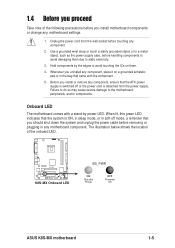
1.8.5 AGP slot The Accelerated Graphics Port (AGP) slot supports AGP 8X/4X (+1.5V) cards. ASUS K8S-MX motherboard 1-15 Install only +1.5V AGP cards. ® K8S-MX Keyed for 1.5v K8S-MX Accelerated Graphics Port (AGP) If installing the ATi 9500 or 9700 Pro Series VGA cards, use only the card version PN xxx-xxxxx-30 or later, for one with +1.5V specification. Note the notches on the motherboard. When you buy an AGP card, make sure that they fit the AGP slot on the card golden fingers to ensure that you ask for optimum performance and overclocking stability.
1.8.5 AGP slot The Accelerated Graphics Port (AGP) slot supports AGP 8X/4X (+1.5V) cards. ASUS K8S-MX motherboard 1-15 Install only +1.5V AGP cards. ® K8S-MX Keyed for 1.5v K8S-MX Accelerated Graphics Port (AGP) If installing the ATi 9500 or 9700 Pro Series VGA cards, use only the card version PN xxx-xxxxx-30 or later, for one with +1.5V specification. Note the notches on the motherboard. When you buy an AGP card, make sure that they fit the AGP slot on the card golden fingers to ensure that you ask for optimum performance and overclocking stability.

K8S-MX English User Manual E1884
Page 27
...up the computer from S1 sleep mode (CPU stopped, DRAM refreshed, system running in low power mode) using the connected USB devices. ASUS K8S-MX motherboard 1-17 Otherwise, the system would not power up. • The total current consumed must NOT exceed the power supply capability (+5VSB...) whether under normal condition or in reduced power mode). ® USBPW34 USBPW12 12 23 K8S-MX +5V +5VSB (Default) USBPW78 USBPW56 12 23 K8S-MX USB device wake-up +5V (Default) +5VSB • The USB device wake-up (3-pin USBPW12, USBPW34, USBPW56,...
...up the computer from S1 sleep mode (CPU stopped, DRAM refreshed, system running in low power mode) using the connected USB devices. ASUS K8S-MX motherboard 1-17 Otherwise, the system would not power up. • The total current consumed must NOT exceed the power supply capability (+5VSB...) whether under normal condition or in reduced power mode). ® USBPW34 USBPW12 12 23 K8S-MX +5V +5VSB (Default) USBPW78 USBPW56 12 23 K8S-MX USB device wake-up +5V (Default) +5VSB • The USB device wake-up (3-pin USBPW12, USBPW34, USBPW56,...
K8S-MX English User Manual E1884
Page 29
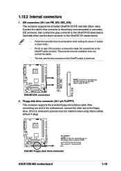
...connectors (40-1 pin PRI_IDE, SEC_IDE) This connector supports the provided UltraATA133 IDE hard disk ribbon cable. PIN 1 K8S-MX Floppy disk drive connector ASUS K8S-MX motherboard 1-19 PIN 1 K8S-MX IDE connectors 2. Floppy disk drive connector (34-1 pin FLOPPY) This connector supports the provided floppy drive ribbon ...; Pin 20 on each IDE connector is removed to prevent incorrect insertion when using ribbon cables with pin 5 plug). ® K8S-MX FLOPPY NOTE: Orient the red markings on the IDE ribbon cable to PIN 1. This prevents incorrect orientation when you connect the cables...
...connectors (40-1 pin PRI_IDE, SEC_IDE) This connector supports the provided UltraATA133 IDE hard disk ribbon cable. PIN 1 K8S-MX Floppy disk drive connector ASUS K8S-MX motherboard 1-19 PIN 1 K8S-MX IDE connectors 2. Floppy disk drive connector (34-1 pin FLOPPY) This connector supports the provided floppy drive ribbon ...; Pin 20 on each IDE connector is removed to prevent incorrect insertion when using ribbon cables with pin 5 plug). ® K8S-MX FLOPPY NOTE: Orient the red markings on the IDE ribbon cable to PIN 1. This prevents incorrect orientation when you connect the cables...

K8S-MX English User Manual E1884
Page 31
...DO NOT place jumper caps on the rear panel are not jumpers! The module has two USB 2.0 ports for additional USB ports. ASUS K8S-MX motherboard USB+5V USB_P5USB_P5+ GND 1-21 Connect the fan cables to the fan connectors. CPU and chassis fan connectors (3-pin CPU_FAN,... generation USB peripherals such as high resolution cameras, scanners, and printers. ® USB+5V USB_P6USB_P6+ GND NC USB+5V USB_P8USB_P8+ GND NC K8S-MX USB78 1 K8S-MX USB 2.0 connectors USB56 1 USB+5V USB_P7USB_P7+ GND • The USB 2.0 module is purchased separately. • Install the USB 2.0 driver...
...DO NOT place jumper caps on the rear panel are not jumpers! The module has two USB 2.0 ports for additional USB ports. ASUS K8S-MX motherboard USB+5V USB_P5USB_P5+ GND 1-21 Connect the fan cables to the fan connectors. CPU and chassis fan connectors (3-pin CPU_FAN,... generation USB peripherals such as high resolution cameras, scanners, and printers. ® USB+5V USB_P6USB_P6+ GND NC USB+5V USB_P8USB_P8+ GND NC K8S-MX USB78 1 K8S-MX USB 2.0 connectors USB56 1 USB+5V USB_P7USB_P7+ GND • The USB 2.0 module is purchased separately. • Install the USB 2.0 driver...

K8S-MX English User Manual E1884
Page 33
... K8S-MX K8S-MX Game connector GAME1 The GAME/MIDI module is available, connect the GAME/MIDI cable to 150 MB/s data transfer rate, faster than the standard parallel ATA with 133MB/s (Ultra ATA/133). ® GND RSATA_RXN2 RSATA_RXP2 GND RSATA_TXN2 RSATA_TXP2 GND K8S-MX K8S-MX SATA connectors GND RSATA_RXN1 RSATA_RXP1 GND RSATA_TXN1 RSATA_TXP1 GND SATA2 SATA1 ASUS K8S-MX...
... K8S-MX K8S-MX Game connector GAME1 The GAME/MIDI module is available, connect the GAME/MIDI cable to 150 MB/s data transfer rate, faster than the standard parallel ATA with 133MB/s (Ultra ATA/133). ® GND RSATA_RXN2 RSATA_RXP2 GND RSATA_TXN2 RSATA_TXP2 GND K8S-MX K8S-MX SATA connectors GND RSATA_RXN1 RSATA_RXP1 GND RSATA_TXN1 RSATA_TXP1 GND SATA2 SATA1 ASUS K8S-MX...

K8S-MX English User Manual E1884
Page 35
... Lead (Yellow 2-pin PWRSW ) This connector connects a switch that controls the system power. Any read or write activity of the specific connector colors as described. ASUS K8S-MX motherboard 1-25 Pressing the power switch turns the system between ON and SLEEP, or ON and SOFT OFF, depending on the BIOS or OS settings...
... Lead (Yellow 2-pin PWRSW ) This connector connects a switch that controls the system power. Any read or write activity of the specific connector colors as described. ASUS K8S-MX motherboard 1-25 Pressing the power switch turns the system between ON and SLEEP, or ON and SOFT OFF, depending on the BIOS or OS settings...

K8S-MX English User Manual E1884
Page 37
BIOS information ASUS K8S-MX motherboard 2-1 Detailed descriptions of the BIOS parameters are also provided. Chapter 2 This chapter tells how to change system settings through the BIOS Setup menus.
BIOS information ASUS K8S-MX motherboard 2-1 Detailed descriptions of the BIOS parameters are also provided. Chapter 2 This chapter tells how to change system settings through the BIOS Setup menus.
K8S-MX English User Manual E1884
Page 39
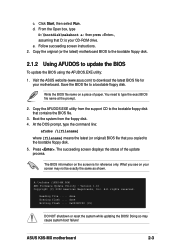
...to the bootable floppy disk. 2.1.2 Using AFUDOS to a bootable floppy disk. The succeeding screen displays the status of paper. A:\>afudos /iK8S-MX.ROM AMI Firmware Update Utility - done Writing flash .... 0x0008CC00 (9%) DO NOT shutdown or reset the system while updating the BIOS! Save the...using the AFUDOS.EXE utility: 1. Copy the AFUDOS.EXE utility from the floppy disk. 4. Doing so may not be exactly the same as shown. ASUS K8S-MX motherboard 2-3 c. d. From the Open box, type D:\bootdisk\makeboot a: then press , assuming that contains the BIOS file. 3. Write the BIOS ...
...to the bootable floppy disk. 2.1.2 Using AFUDOS to a bootable floppy disk. The succeeding screen displays the status of paper. A:\>afudos /iK8S-MX.ROM AMI Firmware Update Utility - done Writing flash .... 0x0008CC00 (9%) DO NOT shutdown or reset the system while updating the BIOS! Save the...using the AFUDOS.EXE utility: 1. Copy the AFUDOS.EXE utility from the floppy disk. 4. Doing so may not be exactly the same as shown. ASUS K8S-MX motherboard 2-3 c. d. From the Open box, type D:\bootdisk\makeboot a: then press , assuming that contains the BIOS file. 3. Write the BIOS ...
K8S-MX English User Manual E1884
Page 41
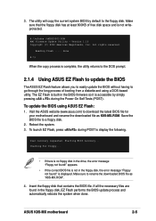
... the utility returns to the DOS prompt. 2.1.4 Using ASUS EZ Flash to update the BIOS The ASUS EZ Flash feature allows you to easily update the BIOS without having to rename the downloaded BIOS file as K8S-MX.ROM. Version 1.10 Copyright (C) 2002 American Megatrends, Inc...floppy disk, the error message "Floppy not found !" A:\>afudos /oMYBIOS03.ROM AMI Firmware Update Utility - Reading flash ..... User recovery requested. ASUS K8S-MX motherboard 2-5 is not in the floppy disk, EZ Flash performs the BIOS update process and automatically reboots the system when done. Reboot the ...
... the utility returns to the DOS prompt. 2.1.4 Using ASUS EZ Flash to update the BIOS The ASUS EZ Flash feature allows you to easily update the BIOS without having to rename the downloaded BIOS file as K8S-MX.ROM. Version 1.10 Copyright (C) 2002 American Megatrends, Inc...floppy disk, the error message "Floppy not found !" A:\>afudos /oMYBIOS03.ROM AMI Firmware Update Utility - Reading flash ..... User recovery requested. ASUS K8S-MX motherboard 2-5 is not in the floppy disk, EZ Flash performs the BIOS update process and automatically reboots the system when done. Reboot the ...
K8S-MX English User Manual E1884
Page 43
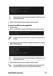
...3. Bad BIOS checksum. Floppy not found . Completed. When the BIOS update process is detected, the following screen message appears. ASUS K8S-MX motherboard 2-7 Reading file "K8S-MX.ROM". DO NOT shut down or reset the system while updating the BIOS! When the BIOS update process is no floppy disk...for CD-ROM... Visit ASUS website (www.asus.com) to download the latest BIOS file. Start flashing... Completed. Starting BIOS recovery... DO NOT shut down or reset the system while updating the BIOS! Floppy found in the CD-ROM. Reading file "K8S-MX.ROM". Doing so ...
...3. Bad BIOS checksum. Floppy not found . Completed. When the BIOS update process is detected, the following screen message appears. ASUS K8S-MX motherboard 2-7 Reading file "K8S-MX.ROM". DO NOT shut down or reset the system while updating the BIOS! When the BIOS update process is no floppy disk...for CD-ROM... Visit ASUS website (www.asus.com) to download the latest BIOS file. Start flashing... Completed. Starting BIOS recovery... DO NOT shut down or reset the system while updating the BIOS! Floppy found in the CD-ROM. Reading file "K8S-MX.ROM". Doing so ...

K8S-MX English User Manual E1884
Page 45
...] Secondary IDE Master : [Not Detected] Secondary IDE Slave : [Not Detected] Onboard PCI S-ATA Controller [Disabled] System Information Use [ENTER], [TAB] or [SHIFT-TAB] to another. ASUS K8S-MX motherboard 2-9 Some of a menu screen are the navigation keys for that particular menu. 2.2.1 BIOS menu screen Menu items Menu bar Configuration fields General help System...
...] Secondary IDE Master : [Not Detected] Secondary IDE Slave : [Not Detected] Onboard PCI S-ATA Controller [Disabled] System Information Use [ENTER], [TAB] or [SHIFT-TAB] to another. ASUS K8S-MX motherboard 2-9 Some of a menu screen are the navigation keys for that particular menu. 2.2.1 BIOS menu screen Menu items Menu bar Configuration fields General help System...

K8S-MX English User Manual E1884
Page 47
...screen items and how to navigate through them. System Time System Date Legacy Diskette A [11:51:19] [Thu 08/05/2003] [1.44M, 3.5 in .] ASUS K8S-MX motherboard 2-11 Configuration options: [Disabled] [360K, 5.25 in.] [1.2M , 5.25 in.] [720K , 3.5 in.] [1.44M, 3.5 in.] [2.88M, 3.5 in... ] Primary IDE Master : [ST320413A] Primary IDE Slave : [ASUS CD-S340] Secondary IDE Master : [Not Detected] Secondary IDE Slave : [Not Detected] Onboard PCI S-ATA Controller [Disabled] System Information Use [ENTER], [TAB] or ...
...screen items and how to navigate through them. System Time System Date Legacy Diskette A [11:51:19] [Thu 08/05/2003] [1.44M, 3.5 in .] ASUS K8S-MX motherboard 2-11 Configuration options: [Disabled] [360K, 5.25 in.] [1.2M , 5.25 in.] [720K , 3.5 in.] [1.44M, 3.5 in.] [2.88M, 3.5 in... ] Primary IDE Master : [ST320413A] Primary IDE Slave : [ASUS CD-S340] Secondary IDE Master : [Not Detected] Secondary IDE Slave : [Not Detected] Onboard PCI S-ATA Controller [Disabled] System Information Use [ENTER], [TAB] or ...
K8S-MX English User Manual E1884
Page 49
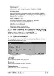
... Athlon9tm) 64 Processor 3200+ : 2007MHz : 1 System Memory Size : 992MB AMI BIOS Displays the auto-detected BIOS information. System Memory Displays the auto-detected system memory. ASUS K8S-MX motherboard 2-13 Configuration options: [Disabled] [Enabled] 2.3.5 Onboard PCI S-ATA Controller [IDE by BIOS. Configuration options: [Auto] [SWDMA0] [SWDMA1] [SWDMA2] [MWDMA0] [MWDMA1] [MWDMA2] [UDMA0] [UDMA1] [UDMA2...
... Athlon9tm) 64 Processor 3200+ : 2007MHz : 1 System Memory Size : 992MB AMI BIOS Displays the auto-detected BIOS information. System Memory Displays the auto-detected system memory. ASUS K8S-MX motherboard 2-13 Configuration options: [Disabled] [Enabled] 2.3.5 Onboard PCI S-ATA Controller [IDE by BIOS. Configuration options: [Auto] [SWDMA0] [SWDMA1] [SWDMA2] [MWDMA0] [MWDMA1] [MWDMA2] [UDMA0] [UDMA1] [UDMA2...


