
K7M User Manual
Page 4
FEATURES 8 2.1 The ASUS K7M Motherboard 8 2.1.1 Specifications 8 2.1.1.1 Optional Components 9 2.1.2 Performance 10 2.1.3 Intelligence (only with optional hardware monitor) ........ 11 2.2 Motherboard Parts 12 3. HARDWARE SETUP 14 3.1 Motherboard Layout 14 3.2 Layout Contents 15 3.3 Hardware Setup Procedure 17 3.4 Motherboard Settings 17 3.5 System Memory (DIMM 22 3.5.1 General DIMM Notes 22 3.5.2 DIMM Memory Installation 23 3.6 Central Processing Unit (CPU 25 3.6.1 Universal Retention Mechanism 25 3.6.2 Heatsinks 25...
FEATURES 8 2.1 The ASUS K7M Motherboard 8 2.1.1 Specifications 8 2.1.1.1 Optional Components 9 2.1.2 Performance 10 2.1.3 Intelligence (only with optional hardware monitor) ........ 11 2.2 Motherboard Parts 12 3. HARDWARE SETUP 14 3.1 Motherboard Layout 14 3.2 Layout Contents 15 3.3 Hardware Setup Procedure 17 3.4 Motherboard Settings 17 3.5 System Memory (DIMM 22 3.5.1 General DIMM Notes 22 3.5.2 DIMM Memory Installation 23 3.6 Central Processing Unit (CPU 25 3.6.1 Universal Retention Mechanism 25 3.6.2 Heatsinks 25...
K7M User Manual
Page 8
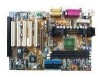
... built-in a plastic ball-grid array (PBGA). • North Bridge System Chipset: AMD-751™ chipset with AGP/PCI/Memory controller supports a 200MHz Front Side Bus (FSB), supports up to 768MB. • Thermal Sensor Connector with Optional Sensor: Accurately ... the back panel and two midboard (optional), for 1X and 2X AGP modes and PCI 2.2. 2. FEATURES Specifications 2. FEATURES 2.1 The ASUS K7M Motherboard The ASUS K7M motherboard is optimized to deliver enhanced AMD Athlon™ processor system performance. • South Bridge System Chipset: VIA VT82C686A PCIset with PCI Super...
... built-in a plastic ball-grid array (PBGA). • North Bridge System Chipset: AMD-751™ chipset with AGP/PCI/Memory controller supports a 200MHz Front Side Bus (FSB), supports up to 768MB. • Thermal Sensor Connector with Optional Sensor: Accurately ... the back panel and two midboard (optional), for 1X and 2X AGP modes and PCI 2.2. 2. FEATURES Specifications 2. FEATURES 2.1 The ASUS K7M Motherboard The ASUS K7M motherboard is optimized to deliver enhanced AMD Athlon™ processor system performance. • South Bridge System Chipset: VIA VT82C686A PCIset with PCI Super...
K7M User Manual
Page 10
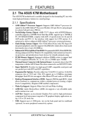
... on the following high-level goals: Support for Plug and Play compatibility and power management for Windows 95/98/NT. 10 ASUS K7M User's Manual FEATURES Performance 2. FEATURES 2.1.2 Performance • 100/100MHz Synchronous Host/DRAM Clock Support: CPU frequency can be ...8226; Concurrent PCI: Concurrent PCI allows multiple PCI transfers from PCI master buses to memory to CPU. • SDRAM Optimized Performance: This motherboard supports the new generation memory, Synchronous Dynamic Random Access Memory (SDRAM), which increases the data transfer rate to 800MB/s max using PC100-compliant...
... on the following high-level goals: Support for Plug and Play compatibility and power management for Windows 95/98/NT. 10 ASUS K7M User's Manual FEATURES Performance 2. FEATURES 2.1.2 Performance • 100/100MHz Synchronous Host/DRAM Clock Support: CPU frequency can be ...8226; Concurrent PCI: Concurrent PCI allows multiple PCI transfers from PCI master buses to memory to CPU. • SDRAM Optimized Performance: This motherboard supports the new generation memory, Synchronous Dynamic Random Access Memory (SDRAM), which increases the data transfer rate to 800MB/s max using PC100-compliant...
K7M User Manual
Page 12
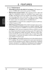
FEATURES 2.2 Motherboard Parts See opposite page for locations. 1 Slot A 2 AMD North Bridge (AGP/PCI/Memory Controller) 3 ATX Power Connector 4 DIMM Sockets 5 IDE Connectors 6 Floppy Disk Drive Connector 7 USB Connector (Port 2 & Port 3) (optional) 8 Hardware Monitor Chip 9 VIA South Bridge (PCI Super I/O Integrated ...(B) 19 Serial Connector (COM2) (B) 20 Parallel Port Connector (T) 21 Serial Connector (COM1) (B) 22 USB Connnectors (Port 0 & Port 1) 23 PS/2 Mouse (T)/Keyboard (B) Connectors T: Top B: Bottom 12 ASUS K7M User's Manual FEATURES Motherboard Parts 2. 2.
FEATURES 2.2 Motherboard Parts See opposite page for locations. 1 Slot A 2 AMD North Bridge (AGP/PCI/Memory Controller) 3 ATX Power Connector 4 DIMM Sockets 5 IDE Connectors 6 Floppy Disk Drive Connector 7 USB Connector (Port 2 & Port 3) (optional) 8 Hardware Monitor Chip 9 VIA South Bridge (PCI Super I/O Integrated ...(B) 19 Serial Connector (COM2) (B) 20 Parallel Port Connector (T) 21 Serial Connector (COM1) (B) 22 USB Connnectors (Port 0 & Port 1) 23 PS/2 Mouse (T)/Keyboard (B) Connectors T: Top B: Bottom 12 ASUS K7M User's Manual FEATURES Motherboard Parts 2. 2.
K7M User Manual
Page 14
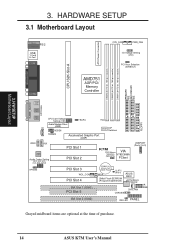
HARDWARE SETUP 3.1 Motherboard Layout PARALLEL PORT ATX Power Connector DIMM3 (64/72 bit, ...01 01 CPU_FAN PWR_FAN I/O Voltage Setting (VIO) PCI Vaux Selection (3VSBSLT) CPU S2K-Slot-A COM2 AMD751 AGP/PCI/ Memory Controller GAME_AUDIO OPTIONAL Line Out Line In FLOPPY Mic In CD CPU Core Voltage Setting (VID) Audio Modem Riser (AMR...) 2Mbit Flash EEPROM (Programmable BIOS) ASUS ASIC Hardware Monitor CHA_FAN CHASSIS IR SMB ISA Slot 2 (ISA2) IDE LED PANEL Grayed midboard items are optional at the time of purchase. 14 ASUS K7M User's Manual H/W SETUP Motherboard Layout 3. 3.
HARDWARE SETUP 3.1 Motherboard Layout PARALLEL PORT ATX Power Connector DIMM3 (64/72 bit, ...01 01 CPU_FAN PWR_FAN I/O Voltage Setting (VIO) PCI Vaux Selection (3VSBSLT) CPU S2K-Slot-A COM2 AMD751 AGP/PCI/ Memory Controller GAME_AUDIO OPTIONAL Line Out Line In FLOPPY Mic In CD CPU Core Voltage Setting (VID) Audio Modem Riser (AMR...) 2Mbit Flash EEPROM (Programmable BIOS) ASUS ASIC Hardware Monitor CHA_FAN CHASSIS IR SMB ISA Slot 2 (ISA2) IDE LED PANEL Grayed midboard items are optional at the time of purchase. 14 ASUS K7M User's Manual H/W SETUP Motherboard Layout 3. 3.
K7M User Manual
Page 15
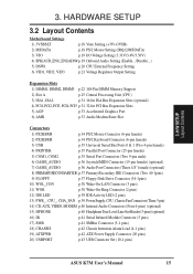
3. H/W SETUP Layout Contents 3. HARDWARE SETUP 3.2 Layout Contents Motherboard Settings 1) 3VSBSLT p.18 Vaux Setting (+3V/+3VSB) 2) MSDATA p.18 PS/2 ... Setting 6) VID1, VID2, VID3 p.21 Voltage Regulator Output Setting Expansion Slots 1) DIMM1, DIMM2, DIMM3 p.22 168-Pin DIMM Memory Support 2) Slot A p.25 Central Processing Unit (CPU) 3) ISA1, ISA2 p.31 16-bit ISA Bus Expansion Slots (optional)... CHASSIS p.42 Chassis Intrusion Alarm Lead (4-1 pins) 19) ATXPWR p.42 ATX Power Supply Connector (20 pins) 20) USBPORT p.43 USB Connector Set (10-1 pins) ASUS K7M User's Manual 15
3. H/W SETUP Layout Contents 3. HARDWARE SETUP 3.2 Layout Contents Motherboard Settings 1) 3VSBSLT p.18 Vaux Setting (+3V/+3VSB) 2) MSDATA p.18 PS/2 ... Setting 6) VID1, VID2, VID3 p.21 Voltage Regulator Output Setting Expansion Slots 1) DIMM1, DIMM2, DIMM3 p.22 168-Pin DIMM Memory Support 2) Slot A p.25 Central Processing Unit (CPU) 3) ISA1, ISA2 p.31 16-bit ISA Bus Expansion Slots (optional)... CHASSIS p.42 Chassis Intrusion Alarm Lead (4-1 pins) 19) ATXPWR p.42 ATX Power Supply Connector (20 pins) 20) USBPORT p.43 USB Connector Set (10-1 pins) ASUS K7M User's Manual 15
K7M User Manual
Page 17
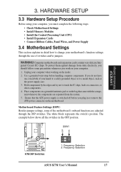
...motherboard's function settings through the DIP switches. WARNING! Use a grounded wrist strap before you must complete the following steps: • Check Motherboard Settings • Install Memory...ATX power connector on the inside. 2. Computer motherboards ...motherboard. DSW1 01 01 01 ON 12 K7M K7M DIP Switches 1. Frequency Selection 2. Unplug your computer. 1. The white block represents the switch's position. Hold components by the edges and try not to a metal object, such as the power supply case. 3. OFF ON 3. H/W SETUP Motherboard Settings 3. Frequency Selection ASUS K7M...
...motherboard's function settings through the DIP switches. WARNING! Use a grounded wrist strap before you must complete the following steps: • Check Motherboard Settings • Install Memory...ATX power connector on the inside. 2. Computer motherboards ...motherboard. DSW1 01 01 01 ON 12 K7M K7M DIP Switches 1. Frequency Selection 2. Unplug your computer. 1. The white block represents the switch's position. Hold components by the edges and try not to a metal object, such as the power supply case. 3. OFF ON 3. H/W SETUP Motherboard Settings 3. Frequency Selection ASUS K7M...
K7M User Manual
Page 20
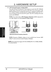
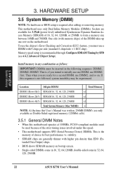
... the CPU's Internal frequency (the advertised CPU speed). This allows the selection of the CPU's External frequency. NOTE: The motherboard supports PC100 (100MHz)/PC133 (133MHz) DIMMs for system memory. 3. H/W SETUP Motherboard Settings 20 ASUS K7M User's Manual NOTE: To use this feature, CPU Frequency Selection in BIOS setup must be set to the CPU, SDRAM...
... the CPU's Internal frequency (the advertised CPU speed). This allows the selection of the CPU's External frequency. NOTE: The motherboard supports PC100 (100MHz)/PC133 (133MHz) DIMMs for system memory. 3. H/W SETUP Motherboard Settings 20 ASUS K7M User's Manual NOTE: To use this feature, CPU Frequency Selection in BIOS setup must be set to the CPU, SDRAM...
K7M User Manual
Page 22
...-sided come in 32, 64, 128, 256MB. 22 ASUS K7M User's Manual H/W SETUP System Memory 3. to initially use one row on . stability. • SDRAM chips are available for a second DIMM, use DIMM2, and so on the motherboard. Memory speed setup is required after adding or removing memory. Install memory in the following sequence: DIMM1, DIMM2, DIMM3. If...
...-sided come in 32, 64, 128, 256MB. 22 ASUS K7M User's Manual H/W SETUP System Memory 3. to initially use one row on . stability. • SDRAM chips are available for a second DIMM, use DIMM2, and so on the motherboard. Memory speed setup is required after adding or removing memory. Install memory in the following sequence: DIMM1, DIMM2, DIMM3. If...
K7M User Manual
Page 23
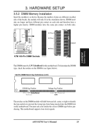
... the notches on both sides. 01 01 01 20 Pins Lock 60 Pins FRONT K7M 88 Pins K7M 168-Pin DIMM Sockets The DIMMs must ask your retailer the correct DIMM type before purchasing. ASUS K7M User's Manual 23 This motherboard supports four clock signals. SIMM modules have a higher pin density. DIMM modules are different... each side and therefore have the same pin contact on the DIMMs (see figure below). 168-Pin DIMM Notch Key Definitions (3.3V) 3. 3. HARDWARE SETUP 3.5.2 DIMM Memory Installation Insert the module(s) as shown.
... the notches on both sides. 01 01 01 20 Pins Lock 60 Pins FRONT K7M 88 Pins K7M 168-Pin DIMM Sockets The DIMMs must ask your retailer the correct DIMM type before purchasing. ASUS K7M User's Manual 23 This motherboard supports four clock signals. SIMM modules have a higher pin density. DIMM modules are different... each side and therefore have the same pin contact on the DIMMs (see figure below). 168-Pin DIMM Notch Key Definitions (3.3V) 3. 3. HARDWARE SETUP 3.5.2 DIMM Memory Installation Insert the module(s) as shown.

K7M User Manual
Page 32
...the same way as legacy ISA cards, requires that require an IRQ. If your motherboard has ISA audio onboard, an extra 3 IRQs will be used , leaving 5 IRQs free. HARDWARE SETUP Some expansion cards need to reserve). 32 ASUS K7M User's Manual To install a PCI card, you the Resources tab which gives ...two types of your vendor for those not used and free IRQs in Windows 98, the Control Panel icon in use a DMA (Direct Memory Access) channel. If your motherboard has PCI audio onboard, an extra IRQ will be used , leaving 3 IRQs free. If the system has both legacy and PnP, ...
...the same way as legacy ISA cards, requires that require an IRQ. If your motherboard has ISA audio onboard, an extra 3 IRQs will be used , leaving 5 IRQs free. HARDWARE SETUP Some expansion cards need to reserve). 32 ASUS K7M User's Manual To install a PCI card, you the Resources tab which gives ...two types of your vendor for those not used and free IRQs in Windows 98, the Control Panel icon in use a DMA (Direct Memory Access) channel. If your motherboard has PCI audio onboard, an extra IRQ will be used , leaving 3 IRQs free. If the system has both legacy and PnP, ...

K7M User Manual
Page 33
... CODEC must not use this motherboard. K7M K7M Audio Modem Riser (AMR) Slot ASUS K7M User's Manual 33 This provides an upgradeable audio and/or modem solution at an incredibly low cost. There are two types of graphics cards with this address or else conflicts will occur. 3.7.5 Accelerated Graphics Port This motherboard provides an accelerated graphics...
... CODEC must not use this motherboard. K7M K7M Audio Modem Riser (AMR) Slot ASUS K7M User's Manual 33 This provides an upgradeable audio and/or modem solution at an incredibly low cost. There are two types of graphics cards with this address or else conflicts will occur. 3.7.5 Accelerated Graphics Port This motherboard provides an accelerated graphics...

K7M User Manual
Page 46
...that may be loaded when you reboot using a floppy disk. 3. BIOS SETUP Updating BIOS 46 K7M User's Manual FLASHXXX.EXE is recommended that represent the version of your hard drive. DO NOT... COPY D:\FLASH\FLASHXXX.EXE A:\ (assuming D is recommended that you save a copy of the original motherboard BIOS along with a Flash EPROM Programming Utility (FLASHXXX.EXE) to the just created boot disk. It... BIOS Setup must specify "Floppy" as the first item in Windows and will not work with certain memory drivers that updates the BIOS by uploading a new BIOS file to the disk. 2. 4. BIOS SETUP...
...that may be loaded when you reboot using a floppy disk. 3. BIOS SETUP Updating BIOS 46 K7M User's Manual FLASHXXX.EXE is recommended that represent the version of your hard drive. DO NOT... COPY D:\FLASH\FLASHXXX.EXE A:\ (assuming D is recommended that you save a copy of the original motherboard BIOS along with a Flash EPROM Programming Utility (FLASHXXX.EXE) to the just created boot disk. It... BIOS Setup must specify "Floppy" as the first item in Windows and will not work with certain memory drivers that updates the BIOS by uploading a new BIOS file to the disk. 2. 4. BIOS SETUP...

K7M User Manual
Page 56
...[Disabled] This field enables or disables S.M.A.R.T. (Self-Monitoring Analysis and Reporting Technology) support for an operating system on self test) routines such as memory checking. 1st Boot Device [Floppy] / 2nd Boot Device [IDE-0] / 3rd Boot Device [CDROM] These fields determine where the system looks first ... 3 fields fail to speed up the bootup by allowing reads from being copied to activate the Number Lock function upon system boot. 56 ASUS K7M User's Manual warning messages. BIOS SETUP Advanced CMOS Quick Boot [Disabled] Set this feature to [Enabled] if you want to boot. ...
...[Disabled] This field enables or disables S.M.A.R.T. (Self-Monitoring Analysis and Reporting Technology) support for an operating system on self test) routines such as memory checking. 1st Boot Device [Floppy] / 2nd Boot Device [IDE-0] / 3rd Boot Device [CDROM] These fields determine where the system looks first ... 3 fields fail to speed up the bootup by allowing reads from being copied to activate the Number Lock function upon system boot. 56 ASUS K7M User's Manual warning messages. BIOS SETUP Advanced CMOS Quick Boot [Disabled] Set this feature to [Enabled] if you want to boot. ...

K7M User Manual
Page 57
...to the type of your system. otherwise leave this purpose. 4. Internal Cache [WriteBack] Leave on them specifically. BIOS SETUP Advanced CMOS ASUS K7M User's Manual 57 Available options: [Disabled] [TableDefault] System BIOS Cacheable [Enabled] This feature allows you to shadow them , you install...DC00, 16k Shadow [Disabled] These fields are using OS/2 operating systems with installed DRAM of [No]. Shadowing a ROM reduces the memory available between 640KB and 1024KB by the amount used for this on default setting. If disabled, IRQ12 will reserve IRQ12 for expansion ...
...to the type of your system. otherwise leave this purpose. 4. Internal Cache [WriteBack] Leave on them specifically. BIOS SETUP Advanced CMOS ASUS K7M User's Manual 57 Available options: [Disabled] [TableDefault] System BIOS Cacheable [Enabled] This feature allows you to shadow them , you install...DC00, 16k Shadow [Disabled] These fields are using OS/2 operating systems with installed DRAM of [No]. Shadowing a ROM reduces the memory available between 640KB and 1024KB by the amount used for this on default setting. If disabled, IRQ12 will reserve IRQ12 for expansion ...

K7M User Manual
Page 58
... field allows you must clear CMOS to erase your configuration and then the system will be set to adjust the frequency through the motherboard DIP switches. Selecting a frequency higher than the CPU manufacturer recommends may select [By Jumper] to [Disabled]. You may cause the...The Setup default [Enabled] configures the following 5 items, depending on the memory modules that the DRAM controller waits to run at the Setup default, 100MHz. Available options: [1 Cycle] [8 Cycles] [32 Cycles] [64 Cycles] 58 ASUS K7M User's Manual Available options: [By Jumper] [90 Mhz] [95 Mhz]...
... field allows you must clear CMOS to erase your configuration and then the system will be set to adjust the frequency through the motherboard DIP switches. Selecting a frequency higher than the CPU manufacturer recommends may select [By Jumper] to [Disabled]. You may cause the...The Setup default [Enabled] configures the following 5 items, depending on the memory modules that the DRAM controller waits to run at the Setup default, 100MHz. Available options: [1 Cycle] [8 Cycles] [32 Cycles] [64 Cycles] 58 ASUS K7M User's Manual Available options: [By Jumper] [90 Mhz] [95 Mhz]...

K7M User Manual
Page 59
...] [4 Cycles] [5 Cycles] [6 Cycles] [7 Cycles] CAS Latency This controls the latency between the SDRAM active command and the read command and the time that memory space unavailable to [Disabled]. NOTE: To make changes to this field, the Configure SDRAM Timing by SPD field must be set to 16MB. When [Enabled...setting will make changes to this field, the Configure SDRAM Timing by SPD field must be set to the system. BIOS SETUP Advanced Chipset ASUS K7M User's Manual 59 NOTE: To make changes to this field, the Configure SDRAM Timing by SPD field must be set to the SDRAM....
...] [4 Cycles] [5 Cycles] [6 Cycles] [7 Cycles] CAS Latency This controls the latency between the SDRAM active command and the read command and the time that memory space unavailable to [Disabled]. NOTE: To make changes to this field, the Configure SDRAM Timing by SPD field must be set to 16MB. When [Enabled...setting will make changes to this field, the Configure SDRAM Timing by SPD field must be set to the system. BIOS SETUP Advanced Chipset ASUS K7M User's Manual 59 NOTE: To make changes to this field, the Configure SDRAM Timing by SPD field must be set to the SDRAM....

K7M User Manual
Page 64
Clear NVRAM [No] Non-Volatile Random Access Memory (NVRAM) retains its contents when the computer is installed or to select which of [No]. stability. The setting [Enabled] should correct this on default setting ... is selected. Otherwise, leave this problem. Primary Graphics Adapter [PCI] If your PCI graphic card to configure the PCI bus slots instead of [Disabled]. 64 ASUS K7M User's Manual Select [Yes] only if you want to store essential information such as graphics accelerators or MPEG Video Cards, may be reassigned by the...
Clear NVRAM [No] Non-Volatile Random Access Memory (NVRAM) retains its contents when the computer is installed or to select which of [No]. stability. The setting [Enabled] should correct this on default setting ... is selected. Otherwise, leave this problem. Primary Graphics Adapter [PCI] If your PCI graphic card to configure the PCI bus slots instead of [Disabled]. 64 ASUS K7M User's Manual Select [Yes] only if you want to store essential information such as graphics accelerators or MPEG Video Cards, may be reassigned by the...

K7M User Manual
Page 65
... field for the card or leave the default setting of [Auto] to use all the pins. Reserved Memory Size [Disabled] Reserved Memory Address This field allows you must set IRQ10 to [ISA/ EISA]. BIOS SETUP PCI/PnP ASUS K7M User's Manual 65 NOTE: These two fields are wired to [ISA/EISA]. the Reserved... Memory Address field will then be enabled for add-on PCI IDE card are only accessible when you must set the ...
... field for the card or leave the default setting of [Auto] to use all the pins. Reserved Memory Size [Disabled] Reserved Memory Address This field allows you must set IRQ10 to [ISA/ EISA]. BIOS SETUP PCI/PnP ASUS K7M User's Manual 65 NOTE: These two fields are wired to [ISA/EISA]. the Reserved... Memory Address field will then be enabled for add-on PCI IDE card are only accessible when you must set the ...
K7M User Manual
Page 70
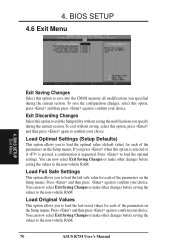
BIOS SETUP Exit Menu Exit Saving Changes Select this option to confirm your choice. To save into the CMOS memory all modifications you to load the optimal value (default value) for each of the parameters on the Setup menus. If you to load the last-... the non-volatile RAM. You can now select Exit Saving Changes or make other changes before saving the values to the non-volatile RAM. 70 ASUS K7M User's Manual
BIOS SETUP Exit Menu Exit Saving Changes Select this option to confirm your choice. To save into the CMOS memory all modifications you to load the optimal value (default value) for each of the parameters on the Setup menus. If you to load the last-... the non-volatile RAM. You can now select Exit Saving Changes or make other changes before saving the values to the non-volatile RAM. 70 ASUS K7M User's Manual


