
H61M-F User's Manual
Page 1
H61M-F Motherboard
H61M-F Motherboard

H61M-F User's Manual
Page 3
Contents Safety information...vi About this guide...vii H61M-F specifications summary ix Package contents...xi Chapter 1: Product introduction 1.1 Special features 1-1 1.1.1 Product highlights 1-1 1.1.2 ASUS Exclusive Features 1-2 1.2 Before you proceed 1-4 1.3 Motherboard overview 1-5 1.3.1 Placement direction 1-5 1.3.2 Screw holes 1-5 1.3.3 Motherboard layout 1-6 1.3.4 Layout contents 1-7 1.4 Central Processing Unit (CPU 1-7 1.4.1 CPU installation 1-8 1.4.2 CPU heatsink and fan assembly installation 1-10 1.5 System memory 1-12 1.5.1 Overview...
Contents Safety information...vi About this guide...vii H61M-F specifications summary ix Package contents...xi Chapter 1: Product introduction 1.1 Special features 1-1 1.1.1 Product highlights 1-1 1.1.2 ASUS Exclusive Features 1-2 1.2 Before you proceed 1-4 1.3 Motherboard overview 1-5 1.3.1 Placement direction 1-5 1.3.2 Screw holes 1-5 1.3.3 Motherboard layout 1-6 1.3.4 Layout contents 1-7 1.4 Central Processing Unit (CPU 1-7 1.4.1 CPU installation 1-8 1.4.2 CPU heatsink and fan assembly installation 1-10 1.5 System memory 1-12 1.5.1 Overview...

H61M-F User's Manual
Page 6
..., contact a qualified service technician or your retailer. If you add a device. • Before connecting or removing signal cables from the motherboard, ensure that all power cables from the existing system before you detect any area where it may become wet. • Place the product... electrical outlet you encounter technical problems with the package. • Before using , contact your area. Operation safety • Before installing the motherboard and adding devices on a stable surface. • If you are using the product, ensure all the manuals that your power supply is ...
..., contact a qualified service technician or your retailer. If you add a device. • Before connecting or removing signal cables from the motherboard, ensure that all power cables from the existing system before you detect any area where it may become wet. • Place the product... electrical outlet you encounter technical problems with the package. • Before using , contact your area. Operation safety • Before installing the motherboard and adding devices on a stable surface. • If you are using the product, ensure all the manuals that your power supply is ...

H61M-F User's Manual
Page 7
... Refer to change system settings through the BIOS Setup menus. vii These documents are also provided. ASUS websites The ASUS website provides updated information on ASUS hardware and software products. Optional documentation Your product package may include optional documentation, such as warranty ...How this guide This user guide contains the information you need when installing and configuring the motherboard. Detailed descriptions of the BIOS parameters are not part of the motherboard and the new technology it supports. • Chapter 2: BIOS information This chapter tells ...
... Refer to change system settings through the BIOS Setup menus. vii These documents are also provided. ASUS websites The ASUS website provides updated information on ASUS hardware and software products. Optional documentation Your product package may include optional documentation, such as warranty ...How this guide This user guide contains the information you need when installing and configuring the motherboard. Detailed descriptions of the BIOS parameters are not part of the motherboard and the new technology it supports. • Chapter 2: BIOS information This chapter tells ...

H61M-F User's Manual
Page 11
... 1042 USB3_E12 Intel® H61 CLRTC SPEAKER 8Mb BIOS F_PANEL SATA3G_3 SATA3G_1 SATA3G_4 SATA3G_2 ASUS H61M-F motherboard User Guide 2 x Serial ATA 3.0 Gb/s cables 1 x I/O Shield User Guide Support DVD • If any of the above are for the following items. KBMS RT 8876 ... 887- Actual product specifications may vary with different models. Package contents Check your retailer. • The illustrations above items is damaged or missing, contact your motherboard package for reference only. xi
... 1042 USB3_E12 Intel® H61 CLRTC SPEAKER 8Mb BIOS F_PANEL SATA3G_3 SATA3G_1 SATA3G_4 SATA3G_2 ASUS H61M-F motherboard User Guide 2 x Serial ATA 3.0 Gb/s cables 1 x I/O Shield User Guide Support DVD • If any of the above are for the following items. KBMS RT 8876 ... 887- Actual product specifications may vary with different models. Package contents Check your retailer. • The illustrations above items is damaged or missing, contact your motherboard package for reference only. xi
H61M-F User's Manual
Page 13
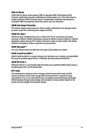
...1866 (O.C.) / 1600 / 1333 / 1066 MHz support The motherboard supports DDR3 memory that provide twice the performance of PCIe 2.0 (in the world. The total bandwidth for a x16 link reaches a maximum of 32Gb/s, double the 16 Gb/s of the current PCIe 2.0. ASUS H61M-F 1-1 Intel® 3rd/2nd generation Core™ i7 /...® 3rd/2nd Generation Core™ i7 / Core™ i5 / Core™ i3 / Pentium® / Celeron® Processors This motherboard supports the Intel® 3rd/2nd generation Core™ i7 / i5 / i3 / Pentium®/ Celeron® processors in the LGA1155 package,...
...1866 (O.C.) / 1600 / 1333 / 1066 MHz support The motherboard supports DDR3 memory that provide twice the performance of PCIe 2.0 (in the world. The total bandwidth for a x16 link reaches a maximum of 32Gb/s, double the 16 Gb/s of the current PCIe 2.0. ASUS H61M-F 1-1 Intel® 3rd/2nd generation Core™ i7 /...® 3rd/2nd Generation Core™ i7 / Core™ i5 / Core™ i3 / Pentium® / Celeron® Processors This motherboard supports the Intel® 3rd/2nd generation Core™ i7 / i5 / i3 / Pentium®/ Celeron® processors in the LGA1155 package,...
H61M-F User's Manual
Page 15
...offer flexible controls of the product and thus mitigate environmental impacts. ErP ready The motherboard is a user-friendly utility that allows you to update the BIOS without the need for any user interaction. ASUS H61M-F 1-3 This is an auto-recovery tool that contains the BIOS file. The ...built-in different geographic regions and your system. ASUS MyLogo2™ Turn your favorite photos into 256-color boot logos to...
...offer flexible controls of the product and thus mitigate environmental impacts. ErP ready The motherboard is a user-friendly utility that allows you to update the BIOS without the need for any user interaction. ASUS H61M-F 1-3 This is an auto-recovery tool that contains the BIOS file. The ...built-in different geographic regions and your system. ASUS MyLogo2™ Turn your favorite photos into 256-color boot logos to...

H61M-F User's Manual
Page 16
... that came with a standby power LED that lights up to the motherboard, peripherals, or components. The illustration below shows the location of the following precautions before you install motherboard components or change any motherboard settings. • Unplug the power cord from the wall socket before... component, place it on a grounded antistatic pad or in the bag that you install or remove any motherboard component. 1.2 Before you proceed Take note of the onboard LED. SB_PWR H61M-F ON OFF Standby Power Powered Off H61M-F Onboard LED 1-4 Chapter 1: Product introduction
... that came with a standby power LED that lights up to the motherboard, peripherals, or components. The illustration below shows the location of the following precautions before you install motherboard components or change any motherboard settings. • Unplug the power cord from the wall socket before... component, place it on a grounded antistatic pad or in the bag that you install or remove any motherboard component. 1.2 Before you proceed Take note of the onboard LED. SB_PWR H61M-F ON OFF Standby Power Powered Off H61M-F Onboard LED 1-4 Chapter 1: Product introduction

H61M-F User's Manual
Page 17
Doing so can damage the motherboard. 1.3 Motherboard overview 1.3.1 Placement direction When installing the motherboard, ensure that you place it into the holes indicated by circles to secure the motherboard to the rear part of the chassis H61M-F ASUS H61M-F 1-5 Place this side towards the rear of the chassis as indicated in the image below. 1.3.2 Screw holes Place six screws into the chassis in the correct orientation. DO NOT overtighten the screws! The edge with external ports goes to the chassis.
Doing so can damage the motherboard. 1.3 Motherboard overview 1.3.1 Placement direction When installing the motherboard, ensure that you place it into the holes indicated by circles to secure the motherboard to the rear part of the chassis H61M-F ASUS H61M-F 1-5 Place this side towards the rear of the chassis as indicated in the image below. 1.3.2 Screw holes Place six screws into the chassis in the correct orientation. DO NOT overtighten the screws! The edge with external ports goes to the chassis.

H61M-F User's Manual
Page 18
1.3.3 Motherboard layout 12 34 3 5 17.8cm(7.0in) KBMS RT 8876 CPU_FAN ATX12V DVI DDR3 DIMM_A1 (64bit, 240-pin module) DDR3 DIMM_B1 (64bit, 240-pin module) VGA LGA1155 22.6cm(8.9in) PS2_USBPW1-4 USB34 EATXPWR CHA_FAN LAN_USB12 RTL 8111F BATTERY 2 AUDIO PCIEX16 H61M-F SATA3G_3 SATA3G_1 SATA3G_4 SATA3G_2 Super I/O PCIEX1_1 SB_PWR ALC 887- VD2 AAFP PCIEX1_2 USBPW_FRONT USB56 ASM 1042 USB3_E12 Intel® 6 H61 CLRTC SPEAKER 64Mb BIOS F_PANEL 14 13 12 11 10 9 8 7 1-6 Chapter 1: Product introduction
1.3.3 Motherboard layout 12 34 3 5 17.8cm(7.0in) KBMS RT 8876 CPU_FAN ATX12V DVI DDR3 DIMM_A1 (64bit, 240-pin module) DDR3 DIMM_B1 (64bit, 240-pin module) VGA LGA1155 22.6cm(8.9in) PS2_USBPW1-4 USB34 EATXPWR CHA_FAN LAN_USB12 RTL 8111F BATTERY 2 AUDIO PCIEX16 H61M-F SATA3G_3 SATA3G_1 SATA3G_4 SATA3G_2 Super I/O PCIEX1_1 SB_PWR ALC 887- VD2 AAFP PCIEX1_2 USBPW_FRONT USB56 ASM 1042 USB3_E12 Intel® 6 H61 CLRTC SPEAKER 64Mb BIOS F_PANEL 14 13 12 11 10 9 8 7 1-6 Chapter 1: Product introduction

H61M-F User's Manual
Page 19
... / i3, Pentium®, and Celeron® processors. ASUS H61M-F 1-7 Intel® LGA1155 CPU socket 5. Intel® H61 Serial ATA 3.0Gb/s connectors (7-pin SATA3G_1/2/3/4) 7. Clear RTC RAM (3-pin CLRTC) 10. H61M-F H61M-F CPU socket LGA1155 Unplug all power cables before installing the CPU. • Upon purchase of the motherboard, ensure that the PnP cap is missing...
... / i3, Pentium®, and Celeron® processors. ASUS H61M-F 1-7 Intel® LGA1155 CPU socket 5. Intel® H61 Serial ATA 3.0Gb/s connectors (7-pin SATA3G_1/2/3/4) 7. Clear RTC RAM (3-pin CLRTC) 10. H61M-F H61M-F CPU socket LGA1155 Unplug all power cables before installing the CPU. • Upon purchase of the motherboard, ensure that the PnP cap is missing...

H61M-F User's Manual
Page 24
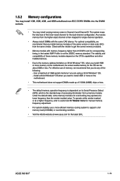
DDR3 modules are developed for better performance with two Double Data Rate 3 (DDR3) Dual Inline Memory Modules (DIMM) sockets. The figure illustrates the location of the DDR3 DIMM sockets: DIMM_A1 DIMM_B1 Channel Channel A Channel B Sockets DIMM_A1 DIMM_B1 H61M-F H61M-F 240-pin DDR3 DIMM sockets 1-12 Chapter 1: Product introduction 1.5 System memory 1.5.1 Overview This motherboard comes with less power consumption. A DDR3 module has the same physical dimensions as a DDR2 DIMM but is notched differently to prevent installation on a DDR2 DIMM socket.
DDR3 modules are developed for better performance with two Double Data Rate 3 (DDR3) Dual Inline Memory Modules (DIMM) sockets. The figure illustrates the location of the DDR3 DIMM sockets: DIMM_A1 DIMM_B1 Channel Channel A Channel B Sockets DIMM_A1 DIMM_B1 H61M-F H61M-F 240-pin DDR3 DIMM sockets 1-12 Chapter 1: Product introduction 1.5 System memory 1.5.1 Overview This motherboard comes with less power consumption. A DDR3 module has the same physical dimensions as a DDR2 DIMM but is notched differently to prevent installation on a DDR2 DIMM socket.
H61M-F User's Manual
Page 25
...limitation on 32-bit Windows® OS, when you install memory modules of the same version or date code (D/C) from a memory module. ASUS H61M-F 1-13 For optimal compatibility, we recommend that you install 4GB or more memory on its corresponding timing or the loaded XMP Profile is ...stability, use of memory, we recommend that you are using a 32-bit Windows® OS. - For effective use a more on the motherboard. • This motherboard does not support DIMMs made up of 512Mb (64MB) chips or less. • The default memory operation frequency is the standard way of ...
...limitation on 32-bit Windows® OS, when you install memory modules of the same version or date code (D/C) from a memory module. ASUS H61M-F 1-13 For optimal compatibility, we recommend that you install 4GB or more memory on its corresponding timing or the loaded XMP Profile is ...stability, use of memory, we recommend that you are using a 32-bit Windows® OS. - For effective use a more on the motherboard. • This motherboard does not support DIMMs made up of 512Mb (64MB) chips or less. • The default memory operation frequency is the standard way of ...
H61M-F User's Manual
Page 27
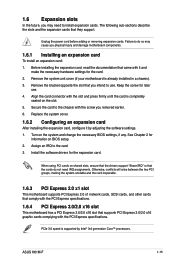
...documentation that came with the PCI Express specifications. Align the card connector with the screw you removed earlier. 6. ASUS H61M-F 1-15 Remove the system unit cover (if your motherboard is supported by adjusting the software settings. 1. Keep the screw for the card. 2. Unplug the power cord ...will arise between the two PCI groups, making the system unstable and the card inoperable. 1.6.3 PCI Express 2.0 x1 slot This motherboard supports PCI Express 2.0 x1 network cards, SCSI cards, and other cards that comply with the PCI Express specifications. 1.6.4 PCI Express 3.0/2.0 x16 ...
...documentation that came with the PCI Express specifications. Align the card connector with the screw you removed earlier. 6. ASUS H61M-F 1-15 Remove the system unit cover (if your motherboard is supported by adjusting the software settings. 1. Keep the screw for the card. 2. Unplug the power cord ...will arise between the two PCI groups, making the system unstable and the card inoperable. 1.6.3 PCI Express 2.0 x1 slot This motherboard supports PCI Express 2.0 x1 network cards, SCSI cards, and other cards that comply with the PCI Express specifications. 1.6.4 PCI Express 3.0/2.0 x16 ...

H61M-F User's Manual
Page 28
F G H - - - - - - - - - - - - - - - - - shared - - - - - - - 1-16 Chapter 1: Product introduction shared - - shared - - - - - shared - shared - - - - - - - - - - - - - - - - - - - - - - shared - shared - - - IRQ assignments for this motherboard PCIEx16 PCIEx1_1 PCIEx1_2 Realtek 8111F controller VGA USB2.0 controller 1 USB2.0 controller 2 HD audio SATA controller 1 SATA controller 2 A B C D E shared - - - - - - shared - - shared - - - -
F G H - - - - - - - - - - - - - - - - - shared - - - - - - - 1-16 Chapter 1: Product introduction shared - - shared - - - - - shared - shared - - - - - - - - - - - - - - - - - - - - - - shared - shared - - - IRQ assignments for this motherboard PCIEx16 PCIEx1_1 PCIEx1_2 Realtek 8111F controller VGA USB2.0 controller 1 USB2.0 controller 2 HD audio SATA controller 1 SATA controller 2 A B C D E shared - - - - - - shared - - shared - - - -

H61M-F User's Manual
Page 32
... cable to this connector, set the item to a PS/2 keyboard. 1.8.2 Internal connectors 1. PS/2 Keyboard port. Connect one end of the motherboard's high-definition audio capability. • If you connect a high-definition front panel audio module to this connector to this connector. This port ...PIN 1 PIN 1 MIC2 MICPWR Line out_R NC Line out_L PORT1 L PORT1 R PORT2 R SENSE_SEND PORT2 L H61M-F HD-audio-compliant Legacy AC'97 pin definition compliant definition H61M-F Front panel audio connector • We recommend that supports either HD Audio or legacy AC`97 audio standard...
... cable to this connector, set the item to a PS/2 keyboard. 1.8.2 Internal connectors 1. PS/2 Keyboard port. Connect one end of the motherboard's high-definition audio capability. • If you connect a high-definition front panel audio module to this connector to this connector. This port ...PIN 1 PIN 1 MIC2 MICPWR Line out_R NC Line out_L PORT1 L PORT1 R PORT2 R SENSE_SEND PORT2 L H61M-F HD-audio-compliant Legacy AC'97 pin definition compliant definition H61M-F Front panel audio connector • We recommend that supports either HD Audio or legacy AC`97 audio standard...
H61M-F User's Manual
Page 35
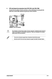
...motherboard, ensuring that the black wire of each cable matches the ground pin of maximum 2A (24 W) fan power. • Only the 4-pin CPU fan and 4-pin chassis fan support the ASUS Fan Xpert feature. CPU and chassis fan connectors (4-pin CPU_FAN, 4-pin CHA_FAN) Connect the fan cables to the fan connectors. 4. ASUS H61M...-F 1-23 CPU_FAN CPU FAN PWM CPU FAN IN CPU FAN PWR GND CHA_FAN H61M-F CHA FAN PWM CHA FAN IN CHA FAN PWR GND H61M-F Fan connectors Do not forget to connect the fan cables to the fan...
...motherboard, ensuring that the black wire of each cable matches the ground pin of maximum 2A (24 W) fan power. • Only the 4-pin CPU fan and 4-pin chassis fan support the ASUS Fan Xpert feature. CPU and chassis fan connectors (4-pin CPU_FAN, 4-pin CHA_FAN) Connect the fan cables to the fan connectors. 4. ASUS H61M...-F 1-23 CPU_FAN CPU FAN PWM CPU FAN IN CPU FAN PWR GND CHA_FAN H61M-F CHA FAN PWM CHA FAN IN CHA FAN PWR GND H61M-F Fan connectors Do not forget to connect the fan cables to the fan...

H61M-F User's Manual
Page 36
...+ IntA_P1_SSTXGND IntA_P1_SSTX+ GND IntA_P1_DIntA_P1_D+ GND USB3+5V IntA_P2_SSRXIntA_P2_SSRX+ GND IntA_P2_SSTXIntA_P2_SSTX+ GND IntA_P2_DIntA_P2_D+ PIN 1 H61M-F H61M-F USB3.0 Front panel connector 1-24 Chapter 1: Product introduction USB connector (10-1 pin USB56) This connector is purchased separately. 6. Doing so will damage the motherboard! The USB module cable is for USB 2.0 ports. Connect the USB module cable to...
...+ IntA_P1_SSTXGND IntA_P1_SSTX+ GND IntA_P1_DIntA_P1_D+ GND USB3+5V IntA_P2_SSRXIntA_P2_SSRX+ GND IntA_P2_SSTXIntA_P2_SSTX+ GND IntA_P2_DIntA_P2_D+ PIN 1 H61M-F H61M-F USB3.0 Front panel connector 1-24 Chapter 1: Product introduction USB connector (10-1 pin USB56) This connector is purchased separately. 6. Doing so will damage the motherboard! The USB module cable is for USB 2.0 ports. Connect the USB module cable to...
H61M-F User's Manual
Page 38
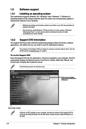
...change at www.asus.com for updates. Visit the ASUS website at any time without notice. Double-click the ASSETUP.EXE to run the Support DVD Place the Support DVD into the optical drive. The following screen is NOT enabled on your hardware. • Motherboard settings and ...introduction Refer to install If Autorun is for better compatibility and system stability. 1.9.2 Support DVD information The Support DVD that comes with the motherboard package contains the drivers, software applications, and utilities that you can install to locate the file ASSETUP.EXE from the BIN folder. ...
...change at www.asus.com for updates. Visit the ASUS website at any time without notice. Double-click the ASSETUP.EXE to run the Support DVD Place the Support DVD into the optical drive. The following screen is NOT enabled on your hardware. • Motherboard settings and ...introduction Refer to install If Autorun is for better compatibility and system stability. 1.9.2 Support DVD information The Support DVD that comes with the motherboard package contains the drivers, software applications, and utilities that you can install to locate the file ASSETUP.EXE from the BIN folder. ...
H61M-F User's Manual
Page 39
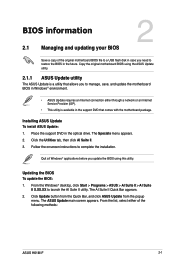
... This utility is a utility that comes with the motherboard package. BIOS information 2.1 Managing and updating your BIOS 2 Save a copy of the following methods: ASUS H61M-F 2-1 The Specials menu appears. 2. From the Windows® desktop, click Start > Programs > ASUS > AI Suite II > AI Suite II X.XX....XX to restore the BIOS in the future. Copy the original motherboard BIOS using this utility. Place ...
... This utility is a utility that comes with the motherboard package. BIOS information 2.1 Managing and updating your BIOS 2 Save a copy of the following methods: ASUS H61M-F 2-1 The Specials menu appears. 2. From the Windows® desktop, click Start > Programs > ASUS > AI Suite II > AI Suite II X.XX....XX to restore the BIOS in the future. Copy the original motherboard BIOS using this utility. Place ...


