H61M-C User's Manual
Page 11
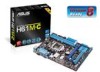
... Super I/O ALC 887 AAFP PCIEX1_1 ASM 64Mb 1083 BIOS PCI1 Intel® H61 USBPW5~10 SPDIF_OUT USB56 SB_PWR USB78 CLRTC USB910 SPEAKER F_PANEL SATA3G_4 SATA3G_3 ASUS H61M-C motherboard User Guide 2 x Serial ATA 3 Gb/s cables 1 x I/O Shield User Guide Support DVD • If any of the above items is damaged or missing, contact your...
... Super I/O ALC 887 AAFP PCIEX1_1 ASM 64Mb 1083 BIOS PCI1 Intel® H61 USBPW5~10 SPDIF_OUT USB56 SB_PWR USB78 CLRTC USB910 SPEAKER F_PANEL SATA3G_4 SATA3G_3 ASUS H61M-C motherboard User Guide 2 x Serial ATA 3 Gb/s cables 1 x I/O Shield User Guide Support DVD • If any of the above items is damaged or missing, contact your...

H61M-C User's Manual
Page 13
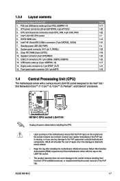
... 3.0 will become a must-have feature for a x16 link reaches a maximum of 32Gb/s, double the 16 Gb/s of the latest 3D graphics, multimedia, and Internet applications. ASUS H61M-C 1-1 Intel® 3rd/2nd generation Core™ i7 / Core™ i5 / Core™ i3, Pentium®, and Celeron® processors are among the most powerful...
... 3.0 will become a must-have feature for a x16 link reaches a maximum of 32Gb/s, double the 16 Gb/s of the latest 3D graphics, multimedia, and Internet applications. ASUS H61M-C 1-1 Intel® 3rd/2nd generation Core™ i7 / Core™ i5 / Core™ i3, Pentium®, and Celeron® processors are among the most powerful...
H61M-C User's Manual
Page 15
...cool environment. The built-in regards to restore a corrupted BIOS file using a bootable floppy disk or an OS-based utility. C.P.R. ASUS EZ Flash 2 ASUS EZ Flash 2 is in line with no need to different ambient temperatures caused by power surges from damage caused by different climate conditions... of the product and thus mitigate environmental impacts. eliminates the need to switch back and forth between different utilities. ASUS H61M-C 1-3 Simply shut down and reboot the system, and the BIOS automatically restores the CPU parameters to launch and operate these ...
...cool environment. The built-in regards to restore a corrupted BIOS file using a bootable floppy disk or an OS-based utility. C.P.R. ASUS EZ Flash 2 ASUS EZ Flash 2 is in line with no need to different ambient temperatures caused by power surges from damage caused by different climate conditions... of the product and thus mitigate environmental impacts. eliminates the need to switch back and forth between different utilities. ASUS H61M-C 1-3 Simply shut down and reboot the system, and the BIOS automatically restores the CPU parameters to launch and operate these ...
H61M-C User's Manual
Page 17
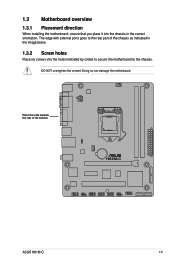
Place this side towards the rear of the chassis as indicated in the image below. 1.3.2 Screw holes Place six screws into the chassis in the correct orientation. Doing so can damage the motherboard. 1.3 Motherboard overview 1.3.1 Placement direction When installing the motherboard, ensure that you place it into the holes indicated by circles to secure the motherboard to the rear part of the chassis H61M-C ASUS H61M-C 1-5 The edge with external ports goes to the chassis. DO NOT overtighten the screws!
Place this side towards the rear of the chassis as indicated in the image below. 1.3.2 Screw holes Place six screws into the chassis in the correct orientation. Doing so can damage the motherboard. 1.3 Motherboard overview 1.3.1 Placement direction When installing the motherboard, ensure that you place it into the holes indicated by circles to secure the motherboard to the rear part of the chassis H61M-C ASUS H61M-C 1-5 The edge with external ports goes to the chassis. DO NOT overtighten the screws!
H61M-C User's Manual
Page 19
... power LED (SB_PWR) 8. Intel® H61 Serial ATA 3.0Gb/s connectors (7-pin SATA3G_1/2/3/4) 7. Speaker connector (4-pin SPEAKER) 11. ASUS H61M-C 1-7 CPU and chassis fan connectors (4-pin CPU_FAN, 4-pin CHA_FAN) 4. Clear RTC RAM (3-pin CLRTC) 10. ASUS will process Return Merchandise Authorization (RMA) requests only if the motherboard comes with a surface mount LGA1155 socket designed...
... power LED (SB_PWR) 8. Intel® H61 Serial ATA 3.0Gb/s connectors (7-pin SATA3G_1/2/3/4) 7. Speaker connector (4-pin SPEAKER) 11. ASUS H61M-C 1-7 CPU and chassis fan connectors (4-pin CPU_FAN, 4-pin CHA_FAN) 4. Clear RTC RAM (3-pin CLRTC) 10. ASUS will process Return Merchandise Authorization (RMA) requests only if the motherboard comes with a surface mount LGA1155 socket designed...
H61M-C User's Manual
Page 23
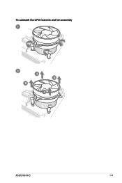
To uninstall the CPU heatsink and fan assembly 1 2 B A B A ASUS H61M-C 1-11
To uninstall the CPU heatsink and fan assembly 1 2 B A B A ASUS H61M-C 1-11

H61M-C User's Manual
Page 25
... manual memory frequency adjustment. • For system stability, use a more efficient memory cooling system to support a full memory load (2 DIMMs) or overclocking condition. 1.5.3 1 Installing a DIMM 2 3 ASUS H61M-C 1-13 To operate at the vendor-marked or at a lower frequency than the vendor-marked value.
... manual memory frequency adjustment. • For system stability, use a more efficient memory cooling system to support a full memory load (2 DIMMs) or overclocking condition. 1.5.3 1 Installing a DIMM 2 3 ASUS H61M-C 1-13 To operate at the vendor-marked or at a lower frequency than the vendor-marked value.
H61M-C User's Manual
Page 27
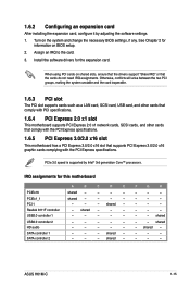
Assign an IRQ to the card. 3. PCIe 3.0 speed is supported by adjusting the software settings. 1. shared - - - - shared - - shared - - - - - - - ASUS H61M-C 1-15 Otherwise, conflicts will arise between the two PCI groups, making the system unstable and the card inoperable. 1.6.3 PCI slot The PCI slot supports cards ...
Assign an IRQ to the card. 3. PCIe 3.0 speed is supported by adjusting the software settings. 1. shared - - - - shared - - shared - - - - - - - ASUS H61M-C 1-15 Otherwise, conflicts will arise between the two PCI groups, making the system unstable and the card inoperable. 1.6.3 PCI slot The PCI slot supports cards ...

H61M-C User's Manual
Page 29
PS2_USBPW1~4 12 23 H61M-C +5V +5VSB (Default) H61M-C PS2/USB device wake-up . • The total current consumed must NOT exceed the power supply capability (+5VSB) whether under normal condition or in low ... device wake-up • The USB device wake-up from S1 sleep mode (CPU stopped, DRAM refreshed, system running in sleep mode. ASUS H61M-C 1-17 Set to +5VSB to pins 2-3 (+5VSB), you set this jumper to +5V to wake up the computer from S3 and S4 sleep modes (no ...
PS2_USBPW1~4 12 23 H61M-C +5V +5VSB (Default) H61M-C PS2/USB device wake-up . • The total current consumed must NOT exceed the power supply capability (+5VSB) whether under normal condition or in low ... device wake-up • The USB device wake-up from S1 sleep mode (CPU stopped, DRAM refreshed, system running in sleep mode. ASUS H61M-C 1-17 Set to +5VSB to pins 2-3 (+5VSB), you set this jumper to +5V to wake up the computer from S3 and S4 sleep modes (no ...
H61M-C User's Manual
Page 31
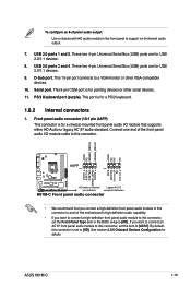
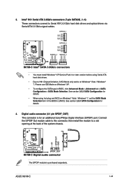
...PIN 1 PIN 1 MIC2 MICPWR Line out_R NC Line out_L PORT1 L PORT1 R PORT2 R SENSE_SEND PORT2 L H61M-C HD-audio-compliant Legacy AC'97 pin definition compliant definition H61M-C Front panel audio connector • We recommend that you connect a high-definition front panel audio module to...front panel audio module to this connector, set the Front Panel Type item in the front panel to a VGA monitor or other serial devices. 11. ASUS H61M-C 1-19 USB 2.0 ports 3 and 4. See section 2.5.6 Onboard Devices Configuration for USB 2.0/1.1 devices. 8. USB 2.0 ports 1 and 2. Connect one...
...PIN 1 PIN 1 MIC2 MICPWR Line out_R NC Line out_L PORT1 L PORT1 R PORT2 R SENSE_SEND PORT2 L H61M-C HD-audio-compliant Legacy AC'97 pin definition compliant definition H61M-C Front panel audio connector • We recommend that you connect a high-definition front panel audio module to...front panel audio module to this connector, set the Front Panel Type item in the front panel to a VGA monitor or other serial devices. 11. ASUS H61M-C 1-19 USB 2.0 ports 3 and 4. See section 2.5.6 Onboard Devices Configuration for USB 2.0/1.1 devices. 8. USB 2.0 ports 1 and 2. Connect one...
H61M-C User's Manual
Page 33
... the SATA type in the BIOS to [AHCI]. See section 2.5.3 SATA Configuration for an additional Sony/Philips Digital Interface (S/PDIF) port. ASUS H61M-C 1-21 Intel® H61 Serial ATA 3.0Gb/s connectors (7-pin SATA3G_1~4) These connectors connect to Serial ATA 3.0 Gb/s hard disk drives...RSATA_TXP2 RSATA_TXN2 GND RSATA_RXN2 RSATA_RXP2 GND SATA3G_4 SATA3G_3 GND RSATA_RXP4 RSATA_RXN4 GND RSATA_TXN4 RSATA_TXP4 GND GND RSATA_RXP3 RSATA_RXN3 GND RSATA_TXN3 RSATA_TXP3 GND H61M-C Intel® SATA 3.0Gb/s connectors • You must install Windows® XP Service Pack 3 or later version ...
... the SATA type in the BIOS to [AHCI]. See section 2.5.3 SATA Configuration for an additional Sony/Philips Digital Interface (S/PDIF) port. ASUS H61M-C 1-21 Intel® H61 Serial ATA 3.0Gb/s connectors (7-pin SATA3G_1~4) These connectors connect to Serial ATA 3.0 Gb/s hard disk drives...RSATA_TXP2 RSATA_TXN2 GND RSATA_RXN2 RSATA_RXP2 GND SATA3G_4 SATA3G_3 GND RSATA_RXP4 RSATA_RXN4 GND RSATA_TXN4 RSATA_TXP4 GND GND RSATA_RXP3 RSATA_RXN3 GND RSATA_TXN3 RSATA_TXP3 GND H61M-C Intel® SATA 3.0Gb/s connectors • You must install Windows® XP Service Pack 3 or later version ...

H61M-C User's Manual
Page 35
The HDD LED lights up when you to this connector. RESET H61M-C System panel connector • System power LED (2-pin +PWR_LED-) This 2-pin connector is for the chassis...• Hard disk drive activity LED (2-pin +HDD_LED-) This 2-pin connector is for the HDD Activity LED. Ground HWRST# (NC) H61M-C PIN 1 +HD_LED- The system power LED lights up or flashes when data is read from or written to this connector. F_PANEL +... chassis power LED cable to hear system beeps and warnings. +5V GND GND Speaker Out SPEAKER H61M-C PIN 1 H61M-C Speaker out connector ASUS H61M-C 1-23
The HDD LED lights up when you to this connector. RESET H61M-C System panel connector • System power LED (2-pin +PWR_LED-) This 2-pin connector is for the chassis...• Hard disk drive activity LED (2-pin +HDD_LED-) This 2-pin connector is for the HDD Activity LED. Ground HWRST# (NC) H61M-C PIN 1 +HD_LED- The system power LED lights up or flashes when data is read from or written to this connector. F_PANEL +... chassis power LED cable to hear system beeps and warnings. +5V GND GND Speaker Out SPEAKER H61M-C PIN 1 H61M-C Speaker out connector ASUS H61M-C 1-23
H61M-C User's Manual
Page 37
... Internet connection either through a network or an ISP (Internet Service Provider. To launch EZ Update, click EZ Update on the AI Suite 3 main menu bar. ASUS H61M-C 2-1 With this utlity, you need to restore the BIOS in the future. Click to automatically update your motherboard's driver, software and firmware Click to find...
... Internet connection either through a network or an ISP (Internet Service Provider. To launch EZ Update, click EZ Update on the AI Suite 3 main menu bar. ASUS H61M-C 2-1 With this utlity, you need to restore the BIOS in the future. Click to automatically update your motherboard's driver, software and firmware Click to find...
H61M-C User's Manual
Page 39
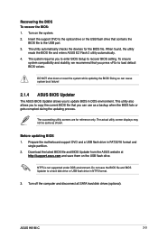
...or reset the system while updating the BIOS! The succeeding utility screens are for the BIOS file. Do not save them on the system. 2. ASUS H61M-C 2-3 Recovering the BIOS To recover the BIOS: 1. To ensure system compatibility and stability, we recommend that you to update BIOS in FAT32/... port. 3. The system requires you press to recover BIOS setting. This utility also allows you can cause system boot failure! 2.1.4 ASUS BIOS Updater The ASUS BIOS Updater allows you to copy the current BIOS file that you to enter BIOS Setup to load default BIOS values. The utility...
...or reset the system while updating the BIOS! The succeeding utility screens are for the BIOS file. Do not save them on the system. 2. ASUS H61M-C 2-3 Recovering the BIOS To recover the BIOS: 1. To ensure system compatibility and stability, we recommend that you to update BIOS in FAT32/... port. 3. The system requires you press to recover BIOS setting. This utility also allows you can cause system boot failure! 2.1.4 ASUS BIOS Updater The ASUS BIOS Updater allows you to copy the current BIOS file that you to enter BIOS Setup to load default BIOS values. The utility...

H61M-C User's Manual
Page 41
... only if you failed to enter BIOS Setup using the BIOS Setup program. See section 1.7 Jumpers for information on your screen. • Visit the ASUS website at startup: • Press during the Power-On Self Test (POST). BIOS menu screen The BIOS setup program can cause damage to guide you...after POST To enter BIOS Setup after changing any BIOS setting, load the default settings to erase the RTC RAM. ASUS H61M-C 2-5 Entering BIOS Setup at startup To enter BIOS Setup at www.asus.com to download the latest BIOS file for this section are for details. • If the system fails to...
... only if you failed to enter BIOS Setup using the BIOS Setup program. See section 1.7 Jumpers for information on your screen. • Visit the ASUS website at startup: • Press during the Power-On Self Test (POST). BIOS menu screen The BIOS setup program can cause damage to guide you...after POST To enter BIOS Setup after changing any BIOS setting, load the default settings to erase the RTC RAM. ASUS H61M-C 2-5 Entering BIOS Setup at startup To enter BIOS Setup at www.asus.com to download the latest BIOS file for this section are for details. • If the system fails to...
H61M-C User's Manual
Page 43
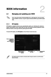
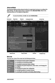
... the fan settings For changing the system boot configuration For configuring options for the detailed configurations. To access the EZ Mode, click Exit, then select ASUS EZ Mode. The figure below shows an example of the screen has the following sections for special functions For selecting the exit options and loading...
... the fan settings For changing the system boot configuration For configuring options for the detailed configurations. To access the EZ Mode, click Exit, then select ASUS EZ Mode. The figure below shows an example of the screen has the following sections for special functions For selecting the exit options and loading...

H61M-C User's Manual
Page 45
... section 1.7 Jumpers for information on how to erase the RTC RAM. • The Administrator or User Password items on top of the BIOS Setup program. ASUS H61M-C 2-9 2.3 Main menu The Main menu screen appears when you have forgotten your BIOS password, erase the CMOS Real Time Clock (RTC) RAM to clear the...
... section 1.7 Jumpers for information on how to erase the RTC RAM. • The Administrator or User Password items on top of the BIOS Setup program. ASUS H61M-C 2-9 2.3 Main menu The Main menu screen appears when you have forgotten your BIOS password, erase the CMOS Real Time Clock (RTC) RAM to clear the...

H61M-C User's Manual
Page 47
... overclocking-related items. Be cautious when changing the settings of the Ai Tweaker menu items. Incorrect field values can cause the system to become unstable! ASUS H61M-C 2-11
... overclocking-related items. Be cautious when changing the settings of the Ai Tweaker menu items. Incorrect field values can cause the system to become unstable! ASUS H61M-C 2-11

H61M-C User's Manual
Page 49
ASUS H61M-C 2-13 2.5 Advanced menu The Advanced menu items allow you to choose the number of the Advanced menu items. Incorrect field values can cause the system ...
ASUS H61M-C 2-13 2.5 Advanced menu The Advanced menu items allow you to choose the number of the Advanced menu items. Incorrect field values can cause the system ...
H61M-C User's Manual
Page 51
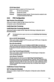
... [Disabled] Allows you to enable or disable the High Precision Event Timer. When the partition size is enough at S3 entry. Configuration options: [Enabled] [Disabled] ASUS H61M-C 2-15 When the item is set the RTC wake timer at S3 entry. Key in order to enable or disable the Active Page Threshold Support...
... [Disabled] Allows you to enable or disable the High Precision Event Timer. When the partition size is enough at S3 entry. Configuration options: [Enabled] [Disabled] ASUS H61M-C 2-15 When the item is set the RTC wake timer at S3 entry. Key in order to enable or disable the Active Page Threshold Support...


