User Manual
Page 1
Motherboard F1A55-M LX Series • F1A55-M LX • F1A55-M LX PLUS
Motherboard F1A55-M LX Series • F1A55-M LX • F1A55-M LX PLUS
User Manual
Page 3
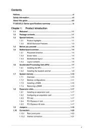
Contents Notices...vi Safety information vii About this guide viii F1A55-M LX Series specifications summary ix Chapter 1: Product introduction 1.1 Welcome 1-1 1.2 Package contents 1-1 1.3 Special features 1-1 1.3.1 Product highlights 1-1 1.3.2 ASUS Exclusive Features 1-2 1.4 Before you proceed 1-4 1.5 Motherboard overview 1-5 1.5.1 Placement direction 1-5 1.5.2 Screw holes 1-5 1.5.3 Motherboard layout 1-6 1.5.4 Layout contents 1-6 1.6 Accelerated Processing Unit (APU 1-7 1.6.1 Installing the APU 1-7 1.6.2 Installing the heatsink and fan 1-9 1.7 System memory...
Contents Notices...vi Safety information vii About this guide viii F1A55-M LX Series specifications summary ix Chapter 1: Product introduction 1.1 Welcome 1-1 1.2 Package contents 1-1 1.3 Special features 1-1 1.3.1 Product highlights 1-1 1.3.2 ASUS Exclusive Features 1-2 1.4 Before you proceed 1-4 1.5 Motherboard overview 1-5 1.5.1 Placement direction 1-5 1.5.2 Screw holes 1-5 1.5.3 Motherboard layout 1-6 1.5.4 Layout contents 1-6 1.6 Accelerated Processing Unit (APU 1-7 1.6.1 Installing the APU 1-7 1.6.2 Installing the heatsink and fan 1-9 1.7 System memory...

User Manual
Page 7
...Restriction of Chemicals) regulatory framework, we published the chemical substances in municipal waste. DO NOT throw the motherboard in our products at ASUS REACH website at http://csr.asus.com/english/REACH.htm. DO NOT throw the mercury-containing button cell battery in your power supply is... voltage of parts and recycling. Safety information Electrical safety • To prevent electric shock hazard, disconnect the power cable from the motherboard, ensure that your area. This product has been designed to enable proper reuse of the electrical outlet you add a device. •...
...Restriction of Chemicals) regulatory framework, we published the chemical substances in municipal waste. DO NOT throw the motherboard in our products at ASUS REACH website at http://csr.asus.com/english/REACH.htm. DO NOT throw the mercury-containing button cell battery in your power supply is... voltage of parts and recycling. Safety information Electrical safety • To prevent electric shock hazard, disconnect the power cable from the motherboard, ensure that your area. This product has been designed to enable proper reuse of the electrical outlet you add a device. •...
User Manual
Page 8
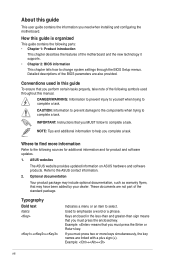
...: means that you must press the enclosed key. Example: ++ viii DANGER/WARNING: Information to prevent injury to yourself when trying to the ASUS contact information. 2. CAUTION: Information to prevent damage to the components when trying to select. Typography Bold text Italics ++ Indicates a menu or..., the key names are linked with a plus sign (+). Detailed descriptions of the BIOS parameters are not part of the motherboard and the new technology it supports. • Chapter 2: BIOS information This chapter tells how to help you need when installing and ...
...: means that you must press the enclosed key. Example: ++ viii DANGER/WARNING: Information to prevent injury to yourself when trying to the ASUS contact information. 2. CAUTION: Information to prevent damage to the components when trying to select. Typography Bold text Italics ++ Indicates a menu or..., the key names are linked with a plus sign (+). Detailed descriptions of the BIOS parameters are not part of the motherboard and the new technology it supports. • Chapter 2: BIOS information This chapter tells how to help you need when installing and ...
User Manual
Page 13
... of the items is damaged or missing, contact your motherboard package for the following items. Motherboard Cables Accessories Application DVD Documentations ASUS F1A55-M LX Series motherboard 2 x Serial ATA 3.0Gb/s cables 1 x I/O shield ASUS motherboard Support DVD User Manual • F1A55-M LX Series motherboards include F1A55-M LX PLUS and F1A55-M LX two models. ASUS F1A55-M LX Series 1-1 Thank you start installing the motherboard, and hardware devices on it another standout in...
... of the items is damaged or missing, contact your motherboard package for the following items. Motherboard Cables Accessories Application DVD Documentations ASUS F1A55-M LX Series motherboard 2 x Serial ATA 3.0Gb/s cables 1 x I/O shield ASUS motherboard Support DVD User Manual • F1A55-M LX Series motherboards include F1A55-M LX PLUS and F1A55-M LX two models. ASUS F1A55-M LX Series 1-1 Thank you start installing the motherboard, and hardware devices on it another standout in...
User Manual
Page 14
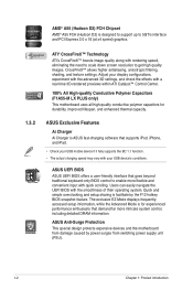
... information, while the Advanced Mode is for durability, improved lifespan, and enhanced thermal capacity. 1.3.2 ASUS Exclusive Features Ai Charger Ai Charger is ASUS fast-charging software that demand far more flexible and convenient input with your USB mobile device if it...with a real-time 3D-rendered previews within ATI Catalyst™ Control Center. 100% All High-quality Conductive Polymer Capacitors (F1A55-M LX PLUS only) This motherboard uses all high-quality conductive polymer capacitors for experienced performance enthusiasts that supports iPod, iPhone, and iPad. • Check...
... information, while the Advanced Mode is for durability, improved lifespan, and enhanced thermal capacity. 1.3.2 ASUS Exclusive Features Ai Charger Ai Charger is ASUS fast-charging software that demand far more flexible and convenient input with your USB mobile device if it...with a real-time 3D-rendered previews within ATI Catalyst™ Control Center. 100% All High-quality Conductive Polymer Capacitors (F1A55-M LX PLUS only) This motherboard uses all high-quality conductive polymer capacitors for experienced performance enthusiasts that supports iPod, iPhone, and iPad. • Check...
User Manual
Page 15
...restores the CPU parameters to overclocking failure. ErP ready The motherboard is a user-friendly utility that allows you to adjust the CPU fan speed according to use software package. Fan Xpert ASUS Fan Xpert intelligently allows you to update the BIOS without ... default settings. eliminates the need to personalize your PC's loading. ASUS F1A55-M LX Series 1-3 This all the exclusive ASUS features into 256-color boot logos to switch back and forth between different utilities. C.P.R. ASUS CrashFree BIOS 3 ASUS CrashFree BIOS 3 is in regards to restore a corrupted BIOS file...
...restores the CPU parameters to overclocking failure. ErP ready The motherboard is a user-friendly utility that allows you to adjust the CPU fan speed according to use software package. Fan Xpert ASUS Fan Xpert intelligently allows you to update the BIOS without ... default settings. eliminates the need to personalize your PC's loading. ASUS F1A55-M LX Series 1-3 This all the exclusive ASUS features into 256-color boot logos to switch back and forth between different utilities. C.P.R. ASUS CrashFree BIOS 3 ASUS CrashFree BIOS 3 is in regards to restore a corrupted BIOS file...
User Manual
Page 16
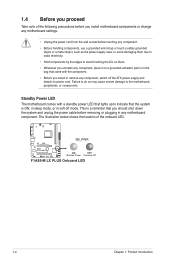
... and detach its power cord. The illustration below shows the location of the following precautions before you install motherboard components or change any motherboard settings. • Unplug the power cord from the wall socket before removing or plugging in the bag ... or in any component, switch off mode. Standby Power LED The motherboard comes with the component. • Before you install or remove any motherboard component. F1A55-M LX PLUS SB_PWR ON OFF Standby Power Powered Off F1A55-M LX PLUS Onboard LED 1-4 Chapter 1: Product introduction 1.4 Before you proceed...
... and detach its power cord. The illustration below shows the location of the following precautions before you install motherboard components or change any motherboard settings. • Unplug the power cord from the wall socket before removing or plugging in the bag ... or in any component, switch off mode. Standby Power LED The motherboard comes with the component. • Before you install or remove any motherboard component. F1A55-M LX PLUS SB_PWR ON OFF Standby Power Powered Off F1A55-M LX PLUS Onboard LED 1-4 Chapter 1: Product introduction 1.4 Before you proceed...
User Manual
Page 17
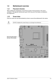
Place this side towards the rear of the chassis as indicated in the image below. 1.5.2 Screw holes Place six screws into the chassis in the correct orientation. Doing so can damage the motherboard. DO NOT overtighten the screws! The edge with external ports goes to the chassis. F1A55-M LX PLUS ASUS F1A55-M LX Series 1-5 1.5 Motherboard overview 1.5.1 Placement direction When installing the motherboard, ensure that you place it into the holes indicated by circles to secure the motherboard to the rear part of the chassis.
Place this side towards the rear of the chassis as indicated in the image below. 1.5.2 Screw holes Place six screws into the chassis in the correct orientation. Doing so can damage the motherboard. DO NOT overtighten the screws! The edge with external ports goes to the chassis. F1A55-M LX PLUS ASUS F1A55-M LX Series 1-5 1.5 Motherboard overview 1.5.1 Placement direction When installing the motherboard, ensure that you place it into the holes indicated by circles to secure the motherboard to the rear part of the chassis.
User Manual
Page 18
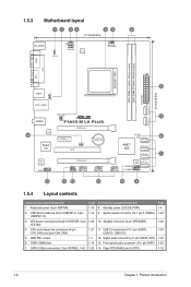
... FM1 socket 1-7 12. 1.5.3 Motherboard layout 1 2 34 54 6 21.3cm(8.4in) KB_USB56 KBPWR ATX12V EPU CPU_FAN COM1 SOCKET FM1 DDR3 DIMM_A1 (64bit, 240-pin module) DDR3 DIMM_B1 (64bit, 240-pin module) EATXPWR SATA3G_5 SATA3G_6 24.4cm(9.6in) LPT VGA 3 USB34 USBPW1-6 LAN1_USB12 AUDIO 14 RTL 8111E Super I/O CHA_FAN F1A55-M LX PLUS PCIEX16_1 PCIEX1_1 CLRTC...
... FM1 socket 1-7 12. 1.5.3 Motherboard layout 1 2 34 54 6 21.3cm(8.4in) KB_USB56 KBPWR ATX12V EPU CPU_FAN COM1 SOCKET FM1 DDR3 DIMM_A1 (64bit, 240-pin module) DDR3 DIMM_B1 (64bit, 240-pin module) EATXPWR SATA3G_5 SATA3G_6 24.4cm(9.6in) LPT VGA 3 USB34 USBPW1-6 LAN1_USB12 AUDIO 14 RTL 8111E Super I/O CHA_FAN F1A55-M LX PLUS PCIEX16_1 PCIEX1_1 CLRTC...
User Manual
Page 19
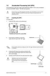
... E2- series accelerated processors with a small triangle. 4. Locate the FM1 socket on the motherboard. The APU fits only in only one correct orientation. 1.6 Accelerated Processing Unit (APU) This motherboard comes with an FM1 socket designed for the FM1 socket. Socket lever Ensure that the socket...DO NOT force the APU into the socket to prevent bending the pins and damaging the APU! F1A55-M LX PLUS F1A55-M LX PLUS CPU socket FM1 2. Small triangle Gold triangle ASUS F1A55-M LX Series 1-7 Ensure that the APU corner with the gold triangle matches the socket corner with AMD...
... E2- series accelerated processors with a small triangle. 4. Locate the FM1 socket on the motherboard. The APU fits only in only one correct orientation. 1.6 Accelerated Processing Unit (APU) This motherboard comes with an FM1 socket designed for the FM1 socket. Socket lever Ensure that the socket...DO NOT force the APU into the socket to prevent bending the pins and damaging the APU! F1A55-M LX PLUS F1A55-M LX PLUS CPU socket FM1 2. Small triangle Gold triangle ASUS F1A55-M LX Series 1-7 Ensure that the APU corner with the gold triangle matches the socket corner with AMD...
User Manual
Page 20
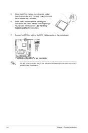
... lever to connect the CPU fan connector! CPU_FAN F1A55-M LX PLUS F1A55-M LX PLUS CPU fan connector DO NOT forget to secure the APU. When the APU is locked. 6. CPU FAN PWM CPU FAN IN CPU FAN PWR GND 1-8 Chapter 1: Product introduction The lever clicks on the motherboard. Connect the CPU fan cable to the...
... lever to connect the CPU fan connector! CPU_FAN F1A55-M LX PLUS F1A55-M LX PLUS CPU fan connector DO NOT forget to secure the APU. When the APU is locked. 6. CPU FAN PWM CPU FAN IN CPU FAN PWR GND 1-8 Chapter 1: Product introduction The lever clicks on the motherboard. Connect the CPU fan cable to the...
User Manual
Page 21
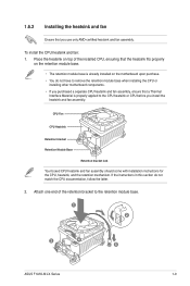
... module base when installing the CPU or installing other motherboard components. • If you use only AMD-certified heatsink and fan assembly. Attach one end of the installed CPU, ensuring that a Thermal Interface Material is properly applied to the retention module base. 1 2 3 4 5 ASUS F1A55-M LX Series 1-9 1.6.2 Installing the heatsink and fan Ensure that you...
... module base when installing the CPU or installing other motherboard components. • If you use only AMD-certified heatsink and fan assembly. Attach one end of the installed CPU, ensuring that a Thermal Interface Material is properly applied to the retention module base. 1 2 3 4 5 ASUS F1A55-M LX Series 1-9 1.6.2 Installing the heatsink and fan Ensure that you...
User Manual
Page 22
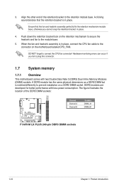
... bracket to connect the CPU fan connector! Align the other end of the DDR3 DIMM sockets: DIMM_A1 DIMM_B1 F1A55-M LX PLUS Channel Channel A Channel B Sockets DIMM_A1 DIMM_B1 F1A55-M LX PLUS 240-pin DDR3 DIMM sockets 1-10 Chapter 1: Product introduction A clicking sound denotes that the fan and...When the fan and heatsink assembly is in place, connect the CPU fan cable to plug this connector. 1.7 System memory 1.7.1 Overview This motherboard comes with less power consumption. DO NOT forget to the retention module base. A DDR3 module has the same physical dimensions as a DDR2...
... bracket to connect the CPU fan connector! Align the other end of the DDR3 DIMM sockets: DIMM_A1 DIMM_B1 F1A55-M LX PLUS Channel Channel A Channel B Sockets DIMM_A1 DIMM_B1 F1A55-M LX PLUS 240-pin DDR3 DIMM sockets 1-10 Chapter 1: Product introduction A clicking sound denotes that the fan and...When the fan and heatsink assembly is in place, connect the CPU fan cable to plug this connector. 1.7 System memory 1.7.1 Overview This motherboard comes with less power consumption. DO NOT forget to the retention module base. A DDR3 module has the same physical dimensions as a DDR2...
User Manual
Page 23
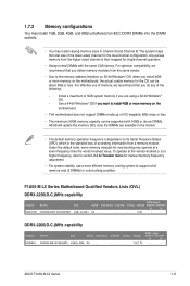
...;o�n��t�h�e� motherboard. • This motherboard does not support DIMMs made up of 512 megabits (Mb) chips or less. • The maximum 32GB memory capacity can be supported with the same CAS latency. Voltage 1.5V-1.7V DIMM socket support (Optional) A* B* • • ASUS F1A55-M LX Series 1-11 For effective use a more...
...;o�n��t�h�e� motherboard. • This motherboard does not support DIMMs made up of 512 megabits (Mb) chips or less. • The maximum 32GB memory capacity can be supported with the same CAS latency. Voltage 1.5V-1.7V DIMM socket support (Optional) A* B* • • ASUS F1A55-M LX Series 1-11 For effective use a more...

User Manual
Page 28
... NOT force a DIMM into the socket until the retaining clips snap back in only one direction. Simultaneously press the retaining clips outward to both the motherboard and the components. 1. Failure to do so can cause severe damage to unlock the DIMM. 2 Support the DIMM lightly with extra force. 1 2. The DIMM might...
... NOT force a DIMM into the socket until the retaining clips snap back in only one direction. Simultaneously press the retaining clips outward to both the motherboard and the components. 1. Failure to do so can cause severe damage to unlock the DIMM. 2 Support the DIMM lightly with extra force. 1 2. The DIMM might...
User Manual
Page 29
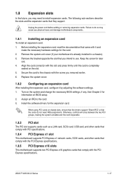
... IRQ" or that you removed earlier. 6. 1.8 Expansion slots In the future, you may cause you physical injury and damage motherboard components. 1.8.1 Installing an expansion card To install an expansion card: 1. The following sub‑sections describe the slots and the...ASUS F1A55-M LX Series 1-17 Otherwise, conflicts will arise between the two PCI groups, making the system unstable and the card inoperable. 1.8.3 PCI slot The PCI slot supports cards such as a LAN card, SCSI card, USB card, and other cards that comply with PCI specifications. 1.8.4 PCI Express x1 slot This motherboard...
... IRQ" or that you removed earlier. 6. 1.8 Expansion slots In the future, you may cause you physical injury and damage motherboard components. 1.8.1 Installing an expansion card To install an expansion card: 1. The following sub‑sections describe the slots and the...ASUS F1A55-M LX Series 1-17 Otherwise, conflicts will arise between the two PCI groups, making the system unstable and the card inoperable. 1.8.3 PCI slot The PCI slot supports cards such as a LAN card, SCSI card, USB card, and other cards that comply with PCI specifications. 1.8.4 PCI Express x1 slot This motherboard...
User Manual
Page 30
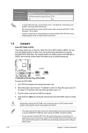
...x16 graphics card to default values. 1-18 Chapter 1: Product introduction See page 1-22 for details. • Connect a chassis fan to the motherboard connector labeled CHA_FAN when using multiple graphics cards for about 5~10 seconds, then move the jumper again to pins 2-3. Keep the cap on ... You can automatically reset parameter settings to get better performance. • We recommend that you to pins 1-2. 3. F1A55-M LX PLUS CLRTC 12 23 Normal (Default) Clear RTC F1A55-M LX PLUS Clear RTC RAM To erase the RTC RAM: 1. Turn OFF the computer and unplug the power cord. 2....
...x16 graphics card to default values. 1-18 Chapter 1: Product introduction See page 1-22 for details. • Connect a chassis fan to the motherboard connector labeled CHA_FAN when using multiple graphics cards for about 5~10 seconds, then move the jumper again to pins 2-3. Keep the cap on ... You can automatically reset parameter settings to get better performance. • We recommend that you to pins 1-2. 3. F1A55-M LX PLUS CLRTC 12 23 Normal (Default) Clear RTC F1A55-M LX PLUS Clear RTC RAM To erase the RTC RAM: 1. Turn OFF the computer and unplug the power cord. 2....
User Manual
Page 33
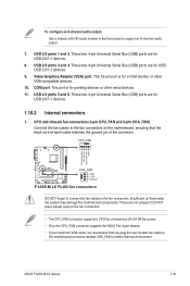
...CPU FAN IN CPU FAN PWR GND F1A55-M LX PLUS CHA_FAN GND +12V Rotation F1A55-M LX PLUS fan connectors DO NOT forget to connect the fan cables to support an 8-channel audio output. 7. Insufficient air flow inside the system may damage the motherboard components. DO NOT place jumper caps... on the motherboard, ensuring that you install two VGA cards, we recommend that the black wire of each cable matches the ground pin of the connector. ASUS F1A55-M LX Series 1-21 This port is for USB 2.0/1.1...
...CPU FAN IN CPU FAN PWR GND F1A55-M LX PLUS CHA_FAN GND +12V Rotation F1A55-M LX PLUS fan connectors DO NOT forget to connect the fan cables to support an 8-channel audio output. 7. Insufficient air flow inside the system may damage the motherboard components. DO NOT place jumper caps... on the motherboard, ensuring that you install two VGA cards, we recommend that the black wire of each cable matches the ground pin of the connector. ASUS F1A55-M LX Series 1-21 This port is for USB 2.0/1.1...
User Manual
Page 37
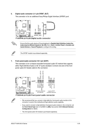
... Panel > Sounds and Audio Devices > Sound Playback to this connector, set the Front Panel Type item in the BIOS to [HD]. ASUS F1A55-M LX Series 1-25 Digital audio connector (4-1 pin SPDIF_OUT) This connector is for a chassis-mounted front panel audio I /O module is for an...Line out_L PORT1 L PORT1 R PORT2 R SENSE_SEND PORT2 L F1A55-M LX PLUS HD-audio-compliant Legacy AC'97 pin definition compliant definition F1A55-M LX PLUS Front panel audio connector • We recommend that the audio device of the motherboard high-definition audio capability. • If you want to...
... Panel > Sounds and Audio Devices > Sound Playback to this connector, set the Front Panel Type item in the BIOS to [HD]. ASUS F1A55-M LX Series 1-25 Digital audio connector (4-1 pin SPDIF_OUT) This connector is for a chassis-mounted front panel audio I /O module is for an...Line out_L PORT1 L PORT1 R PORT2 R SENSE_SEND PORT2 L F1A55-M LX PLUS HD-audio-compliant Legacy AC'97 pin definition compliant definition F1A55-M LX PLUS Front panel audio connector • We recommend that the audio device of the motherboard high-definition audio capability. • If you want to...


