User Manual
Page 1
Motherboard F1A55-M LX Series • F1A55-M LX • F1A55-M LX PLUS
Motherboard F1A55-M LX Series • F1A55-M LX • F1A55-M LX PLUS
User Manual
Page 3
Contents Notices...vi Safety information vii About this guide viii F1A55-M LX Series specifications summary ix Chapter 1: Product introduction 1.1 Welcome 1-1 1.2 Package contents 1-1 1.3 Special features 1-1 1.3.1 Product highlights 1-1 1.3.2 ASUS Exclusive Features 1-2 1.4 Before you proceed 1-4 1.5 Motherboard overview 1-5 1.5.1 Placement direction 1-5 1.5.2 Screw holes 1-5 1.5.3 Motherboard layout 1-6 1.5.4 Layout contents 1-6 1.6 Accelerated Processing Unit (APU 1-7 1.6.1 Installing the APU 1-7 1.6.2 Installing the heatsink and fan 1-9 1.7 System memory...
Contents Notices...vi Safety information vii About this guide viii F1A55-M LX Series specifications summary ix Chapter 1: Product introduction 1.1 Welcome 1-1 1.2 Package contents 1-1 1.3 Special features 1-1 1.3.1 Product highlights 1-1 1.3.2 ASUS Exclusive Features 1-2 1.4 Before you proceed 1-4 1.5 Motherboard overview 1-5 1.5.1 Placement direction 1-5 1.5.2 Screw holes 1-5 1.5.3 Motherboard layout 1-6 1.5.4 Layout contents 1-6 1.6 Accelerated Processing Unit (APU 1-7 1.6.1 Installing the APU 1-7 1.6.2 Installing the heatsink and fan 1-9 1.7 System memory...

User Manual
Page 7
...signal cables from connectors, slots, sockets and circuitry. • Avoid dust, humidity, and temperature extremes. Operation safety • Before installing the motherboard and adding devices on a stable surface. • If you encounter technical problems with the package. • Before using an adapter or ...from the existing system before using the product, ensure that the battery should not be placed in our products at ASUS REACH website at http://csr.asus.com/english/REACH.htm. These devices could interrupt the grounding circuit. • Ensure that came with the product...
...signal cables from connectors, slots, sockets and circuitry. • Avoid dust, humidity, and temperature extremes. Operation safety • Before installing the motherboard and adding devices on a stable surface. • If you encounter technical problems with the package. • Before using an adapter or ...from the existing system before using the product, ensure that the battery should not be placed in our products at ASUS REACH website at http://csr.asus.com/english/REACH.htm. These devices could interrupt the grounding circuit. • Ensure that came with the product...
User Manual
Page 8
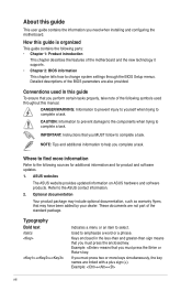
DANGER/WARNING: Information to prevent injury to yourself when trying to select. ASUS websites The ASUS website provides updated information on ASUS hardware and software products. Typography Bold text Italics ++ Indicates a menu or an item to complete a ...Instructions that may include optional documentation, such as warranty flyers, that you MUST follow to help you need when installing and configuring the motherboard. These documents are also provided. NOTE: Tips and additional information to complete a task. Refer to complete a task. CAUTION: Information...
DANGER/WARNING: Information to prevent injury to yourself when trying to select. ASUS websites The ASUS website provides updated information on ASUS hardware and software products. Typography Bold text Italics ++ Indicates a menu or an item to complete a ...Instructions that may include optional documentation, such as warranty flyers, that you MUST follow to help you need when installing and configuring the motherboard. These documents are also provided. NOTE: Tips and additional information to complete a task. Refer to complete a task. CAUTION: Information...
User Manual
Page 13
...) combines processing power and advanced DirectX 11 graphics in this user guide are for the following items. Motherboard Cables Accessories Application DVD Documentations ASUS F1A55-M LX Series motherboard 2 x Serial ATA 3.0Gb/s cables 1 x I/O shield ASUS motherboard Support DVD User Manual • F1A55-M LX Series motherboards include F1A55-M LX PLUS and F1A55-M LX two models. The layout illustrations in one small, energy-efficient design to 5GT/s.
...) combines processing power and advanced DirectX 11 graphics in this user guide are for the following items. Motherboard Cables Accessories Application DVD Documentations ASUS F1A55-M LX Series motherboard 2 x Serial ATA 3.0Gb/s cables 1 x I/O shield ASUS motherboard Support DVD User Manual • F1A55-M LX Series motherboards include F1A55-M LX PLUS and F1A55-M LX two models. The layout illustrations in one small, energy-efficient design to 5GT/s.
User Manual
Page 14
... designed to support up to 5GT/s interface and PCI Express 2.0 x 16 (at x4 speed) graphics. UEFI BIOS Easy & Flexible ASUS UEFI BIOS ASUS UEFI BIOS offers a user-friendly interface that supports iPod, iPhone, and iPad. • Check your USB device's conditions. ATI®... real-time 3D-rendered previews within ATI Catalyst™ Control Center. 100% All High-quality Conductive Polymer Capacitors (F1A55-M LX PLUS only) This motherboard uses all high-quality conductive polymer capacitors for experienced performance enthusiasts that demand far more flexible and convenient input with ...
... designed to support up to 5GT/s interface and PCI Express 2.0 x 16 (at x4 speed) graphics. UEFI BIOS Easy & Flexible ASUS UEFI BIOS ASUS UEFI BIOS offers a user-friendly interface that supports iPod, iPhone, and iPad. • Check your USB device's conditions. ATI®... real-time 3D-rendered previews within ATI Catalyst™ Control Center. 100% All High-quality Conductive Polymer Capacitors (F1A55-M LX PLUS only) This motherboard uses all high-quality conductive polymer capacitors for experienced performance enthusiasts that demand far more flexible and convenient input with ...
User Manual
Page 15
...use software package. feature automatically restores the CPU default settings when the system hangs due to personalize your PC's loading. ErP ready The motherboard is in line with no need to restore a corrupted BIOS file using a bootable floppy disk or an OS-based utility. The ...energy-efficient products through product design and innovation to reduce carbon footprint of fan speed to energy consumptions. ASUS F1A55-M LX Series 1-3 AI Suite II With its fast user-friendly interface, ASUS AI Suite II consolidates all -in-one simple to their default settings. It allows you to adjust...
...use software package. feature automatically restores the CPU default settings when the system hangs due to personalize your PC's loading. ErP ready The motherboard is in line with no need to restore a corrupted BIOS file using a bootable floppy disk or an OS-based utility. The ...energy-efficient products through product design and innovation to reduce carbon footprint of fan speed to energy consumptions. ASUS F1A55-M LX Series 1-3 AI Suite II With its fast user-friendly interface, ASUS AI Suite II consolidates all -in-one simple to their default settings. It allows you to adjust...
User Manual
Page 16
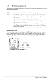
... any component, place it on a grounded antistatic pad or in the bag that came with a standby power LED that lights up to the motherboard, peripherals, or components. This is a reminder that the system is ON, in sleep mode, or in any component, switch off mode. ... detach its power cord. Failure to do so may cause severe damage to indicate that you install or remove any motherboard component. F1A55-M LX PLUS SB_PWR ON OFF Standby Power Powered Off F1A55-M LX PLUS Onboard LED 1-4 Chapter 1: Product introduction 1.4 Before you proceed Take note of the onboard LED.
... any component, place it on a grounded antistatic pad or in the bag that came with a standby power LED that lights up to the motherboard, peripherals, or components. This is a reminder that the system is ON, in sleep mode, or in any component, switch off mode. ... detach its power cord. Failure to do so may cause severe damage to indicate that you install or remove any motherboard component. F1A55-M LX PLUS SB_PWR ON OFF Standby Power Powered Off F1A55-M LX PLUS Onboard LED 1-4 Chapter 1: Product introduction 1.4 Before you proceed Take note of the onboard LED.
User Manual
Page 17
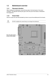
The edge with external ports goes to the rear part of the chassis. Place this side towards the rear of the chassis as indicated in the correct orientation. F1A55-M LX PLUS ASUS F1A55-M LX Series 1-5 DO NOT overtighten the screws! 1.5 Motherboard overview 1.5.1 Placement direction When installing the motherboard, ensure that you place it into the chassis in the image below. 1.5.2 Screw holes Place six screws into the holes indicated by circles to secure the motherboard to the chassis. Doing so can damage the motherboard.
The edge with external ports goes to the rear part of the chassis. Place this side towards the rear of the chassis as indicated in the correct orientation. F1A55-M LX PLUS ASUS F1A55-M LX Series 1-5 DO NOT overtighten the screws! 1.5 Motherboard overview 1.5.1 Placement direction When installing the motherboard, ensure that you place it into the chassis in the image below. 1.5.2 Screw holes Place six screws into the holes indicated by circles to secure the motherboard to the chassis. Doing so can damage the motherboard.
User Manual
Page 18
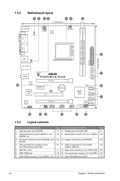
...-1 pin AAFP) 1-25 7. 1.5.3 Motherboard layout 1 2 34 54 6 21.3cm(8.4in) KB_USB56 KBPWR ATX12V EPU CPU_FAN COM1 SOCKET FM1 DDR3 DIMM_A1 (64bit, 240-pin module) DDR3 DIMM_B1 (64bit, 240-pin module) EATXPWR SATA3G_5 SATA3G_6 24.4cm(9.6in) LPT VGA 3 USB34 USBPW1-6 LAN1_USB12 AUDIO 14 RTL 8111E Super I/O CHA_FAN F1A55-M LX PLUS PCIEX16_1 PCIEX1_1 CLRTC...
...-1 pin AAFP) 1-25 7. 1.5.3 Motherboard layout 1 2 34 54 6 21.3cm(8.4in) KB_USB56 KBPWR ATX12V EPU CPU_FAN COM1 SOCKET FM1 DDR3 DIMM_A1 (64bit, 240-pin module) DDR3 DIMM_B1 (64bit, 240-pin module) EATXPWR SATA3G_5 SATA3G_6 24.4cm(9.6in) LPT VGA 3 USB34 USBPW1-6 LAN1_USB12 AUDIO 14 RTL 8111E Super I/O CHA_FAN F1A55-M LX PLUS PCIEX16_1 PCIEX1_1 CLRTC...
User Manual
Page 19
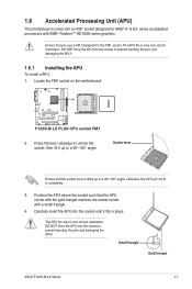
...APU: 1. The APU fits only in completely. 3. series accelerated processors with an FM1 socket designed for the FM1 socket. F1A55-M LX PLUS F1A55-M LX PLUS CPU socket FM1 2. Small triangle Gold triangle ASUS F1A55-M LX Series 1-7 otherwise, the APU will not fit in one correct orientation. Position the APU above the socket such that you use... the APU! DO NOT force the APU into the socket to a 90°-100° angle; Locate the FM1 socket on the motherboard. Press the lever sideways to unlock the socket, then lift it fits in only one correct orientation.
...APU: 1. The APU fits only in completely. 3. series accelerated processors with an FM1 socket designed for the FM1 socket. F1A55-M LX PLUS F1A55-M LX PLUS CPU socket FM1 2. Small triangle Gold triangle ASUS F1A55-M LX Series 1-7 otherwise, the APU will not fit in one correct orientation. Position the APU above the socket such that you use... the APU! DO NOT force the APU into the socket to a 90°-100° angle; Locate the FM1 socket on the motherboard. Press the lever sideways to unlock the socket, then lift it fits in only one correct orientation.
User Manual
Page 20
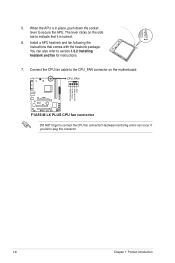
... CPU_FAN connector on the side tab to indicate that comes with the heatsink package. The lever clicks on the motherboard. You can occur if you fail to secure the APU. CPU_FAN F1A55-M LX PLUS F1A55-M LX PLUS CPU fan connector DO NOT forget to section 1.6.2 Installing heatsink and fan for instructions. 7. When the APU is...
... CPU_FAN connector on the side tab to indicate that comes with the heatsink package. The lever clicks on the motherboard. You can occur if you fail to secure the APU. CPU_FAN F1A55-M LX PLUS F1A55-M LX PLUS CPU fan connector DO NOT forget to section 1.6.2 Installing heatsink and fan for instructions. 7. When the APU is...
User Manual
Page 21
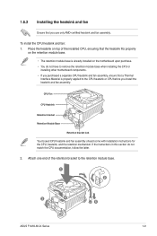
...that a Thermal Interface Material is already installed on top of the retention bracket to the retention module base. 1 2 3 4 5 ASUS F1A55-M LX Series 1-9 CPU Fan CPU Heatsink Retention bracket Retention Module Base Retention bracket lock Your boxed CPU heatsink and fan assembly should come with ...base. • The retention module base is properly applied to remove the retention module base when installing the CPU or installing other motherboard components. • If you purchased a separate CPU heatsink and fan assembly, ensure that you install the heatsink and fan assembly...
...that a Thermal Interface Material is already installed on top of the retention bracket to the retention module base. 1 2 3 4 5 ASUS F1A55-M LX Series 1-9 CPU Fan CPU Heatsink Retention bracket Retention Module Base Retention bracket lock Your boxed CPU heatsink and fan assembly should come with ...base. • The retention module base is properly applied to remove the retention module base when installing the CPU or installing other motherboard components. • If you purchased a separate CPU heatsink and fan assembly, ensure that you install the heatsink and fan assembly...
User Manual
Page 22
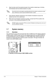
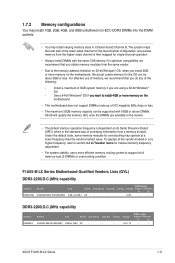
... down the retention bracket lock on a DDR2 DIMM socket. Align the other end of the DDR3 DIMM sockets: DIMM_A1 DIMM_B1 F1A55-M LX PLUS Channel Channel A Channel B Sockets DIMM_A1 DIMM_B1 F1A55-M LX PLUS 240-pin DDR3 DIMM sockets 1-10 Chapter 1: Product introduction When the fan and heatsink assembly is in place. 4. ... secure the heatsink and fan to the module base. 5. DO NOT forget to plug this connector. 1.7 System memory 1.7.1 Overview This motherboard comes with less power consumption. The figure illustrates the location of the retention bracket to the connector on the...
... down the retention bracket lock on a DDR2 DIMM socket. Align the other end of the DDR3 DIMM sockets: DIMM_A1 DIMM_B1 F1A55-M LX PLUS Channel Channel A Channel B Sockets DIMM_A1 DIMM_B1 F1A55-M LX PLUS 240-pin DDR3 DIMM sockets 1-10 Chapter 1: Product introduction When the fan and heatsink assembly is in place. 4. ... secure the heatsink and fan to the module base. 5. DO NOT forget to plug this connector. 1.7 System memory 1.7.1 Overview This motherboard comes with less power consumption. The figure illustrates the location of the retention bracket to the connector on the...
User Manual
Page 23
...Chip Brand FLKE85F-B8KJA FEIH(XMP) 4GB(2 x 2GB) DS - Voltage 1.5V-1.7V DIMM socket support (Optional) A* B* • • ASUS F1A55-M LX Series 1-11 Chip NO. - KHX2250C9D3T1K2/4GX(XMP) Size SS/DS 4GB ( 2x 2GB ) DS Chip Brand - Use a 64-bit Windows&#...65533;r�y��o�n��t�h�e� motherboard. • This motherboard does not support DIMMs made up of the lower-sized channel for the dual-channel configuration. F1A55-M LX Series Motherboard Qualified Vendors Lists (QVL) DDR3-2250(O.C.)MHz capability Vendors...
...Chip Brand FLKE85F-B8KJA FEIH(XMP) 4GB(2 x 2GB) DS - Voltage 1.5V-1.7V DIMM socket support (Optional) A* B* • • ASUS F1A55-M LX Series 1-11 Chip NO. - KHX2250C9D3T1K2/4GX(XMP) Size SS/DS 4GB ( 2x 2GB ) DS Chip Brand - Use a 64-bit Windows&#...65533;r�y��o�n��t�h�e� motherboard. • This motherboard does not support DIMMs made up of the lower-sized channel for the dual-channel configuration. F1A55-M LX Series Motherboard Qualified Vendors Lists (QVL) DDR3-2250(O.C.)MHz capability Vendors...

User Manual
Page 28
Simultaneously press the retaining clips outward to both the motherboard and the components. 1. DIMM notch 1-16 Chapter 1: Product introduction Firmly insert the DIMM into a socket in the wrong direction to unlock a DIMM socket. 2. Align a DIMM ...
Simultaneously press the retaining clips outward to both the motherboard and the components. 1. DIMM notch 1-16 Chapter 1: Product introduction Firmly insert the DIMM into a socket in the wrong direction to unlock a DIMM socket. 2. Align a DIMM ...
User Manual
Page 29
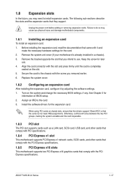
... a LAN card, SCSI card, USB card, and other cards that comply with PCI specifications. 1.8.4 PCI Express x1 slot This motherboard supports PCI Express x1 network cards, SCSI cards, and other cards that comply with the PCI Express specifications. 1.8.5 PCI Express x16 slots This... or that came with the screw you physical injury and damage motherboard components. 1.8.1 Installing an expansion card To install an expansion card: 1. Assign an IRQ to the chassis with it by adjusting the software settings. 1. ASUS F1A55-M LX Series 1-17 Keep the screw for information on the system and ...
... a LAN card, SCSI card, USB card, and other cards that comply with PCI specifications. 1.8.4 PCI Express x1 slot This motherboard supports PCI Express x1 network cards, SCSI cards, and other cards that comply with the PCI Express specifications. 1.8.5 PCI Express x16 slots This... or that came with the screw you physical injury and damage motherboard components. 1.8.1 Installing an expansion card To install an expansion card: 1. Assign an IRQ to the chassis with it by adjusting the software settings. 1. ASUS F1A55-M LX Series 1-17 Keep the screw for information on the system and ...
User Manual
Page 30
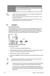
... 12 23 Normal (Default) Clear RTC F1A55-M LX PLUS Clear RTC RAM To erase the RTC RAM: 1. Move the jumper cap from pins 1-2 (default) to overclocking. Plug the power cord and turn ON ... card to get better performance. • We recommend that you to clear the CMOS RTC RAM data. You can automatically reset parameter settings to the motherboard connector labeled CHA_FAN when using multiple graphics cards for better thermal environment. 1.9 Jumpers Clear RTC RAM (CLRTC) This jumper allows you provide sufficient power when...
... 12 23 Normal (Default) Clear RTC F1A55-M LX PLUS Clear RTC RAM To erase the RTC RAM: 1. Move the jumper cap from pins 1-2 (default) to overclocking. Plug the power cord and turn ON ... card to get better performance. • We recommend that you to clear the CMOS RTC RAM data. You can automatically reset parameter settings to the motherboard connector labeled CHA_FAN when using multiple graphics cards for better thermal environment. 1.9 Jumpers Clear RTC RAM (CLRTC) This jumper allows you provide sufficient power when...
User Manual
Page 33
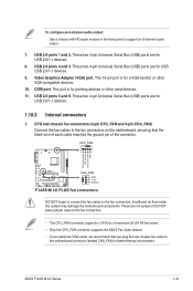
USB 2.0 ports 3 and 4. This 15-pin port is for better thermal environment. Insufficient air flow inside the system may damage the motherboard components. ASUS F1A55-M LX Series 1-21 These two 4-pin Universal Serial Bus (USB) ports are for USB 2.0/1.1 devices. 8. These two 4-pin Universal Serial Bus (USB) ports are for USB 2.0/1.1 ...
USB 2.0 ports 3 and 4. This 15-pin port is for better thermal environment. Insufficient air flow inside the system may damage the motherboard components. ASUS F1A55-M LX Series 1-21 These two 4-pin Universal Serial Bus (USB) ports are for USB 2.0/1.1 devices. 8. These two 4-pin Universal Serial Bus (USB) ports are for USB 2.0/1.1 ...
User Manual
Page 37
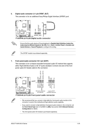
... motherboard high-definition audio capability. • If you connect a high-definition front panel audio module to this connector. See section 2.5.5 Onboard Devices Configuration for an additional Sony/Philips Digital Interface (S/PDIF) port. +5V SPDIFOUT GND F1A55-M LX PLUS SPDIF_OUT F1A55-M LX ...PLUS Digital audio connector Ensure that supports either High Definition Audio or AC`97 audio standard. The S/PDIF module is purchased separately. ASUS F1A55-M LX Series 1-25 Front panel audio connector (...
... motherboard high-definition audio capability. • If you connect a high-definition front panel audio module to this connector. See section 2.5.5 Onboard Devices Configuration for an additional Sony/Philips Digital Interface (S/PDIF) port. +5V SPDIFOUT GND F1A55-M LX PLUS SPDIF_OUT F1A55-M LX ...PLUS Digital audio connector Ensure that supports either High Definition Audio or AC`97 audio standard. The S/PDIF module is purchased separately. ASUS F1A55-M LX Series 1-25 Front panel audio connector (...


