User Manual
Page 13
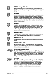
... you for the following items. Motherboard Cables Accessories Application DVD Documentations ASUS F1A55-M LE motherboard 2 x Serial ATA 3.0Gb/s cables 1 x I/O shield ASUS motherboard Support DVD User Manual If any of ASUS quality motherboards! This revolutionary APU (Accelerated Processing Unit) combines processing ...174; Radeon™ HD 6000 series graphics This motherboard supports AMD® A- & E2- Chapter 1 Product introduction 1.1 Welcome! ASUS F1A55-M LE 1-1 The motherboard delivers a host of new features and latest technologies, making it , check the items in the long line of...
... you for the following items. Motherboard Cables Accessories Application DVD Documentations ASUS F1A55-M LE motherboard 2 x Serial ATA 3.0Gb/s cables 1 x I/O shield ASUS motherboard Support DVD User Manual If any of ASUS quality motherboards! This revolutionary APU (Accelerated Processing Unit) combines processing ...174; Radeon™ HD 6000 series graphics This motherboard supports AMD® A- & E2- Chapter 1 Product introduction 1.1 Welcome! ASUS F1A55-M LE 1-1 The motherboard delivers a host of new features and latest technologies, making it , check the items in the long line of...
User Manual
Page 15
... (CPU Parameter Recall) The BIOS C.P.R. ASUS CrashFree BIOS 3 ASUS CrashFree BIOS 3 is a user-friendly utility that allows you to adjust the CPU fan speed according to achieve a quiet and cool environment. ASUS F1A55-M LE 1-3 Fan Xpert ASUS Fan Xpert intelligently allows you to supervise ...overclocking, energy management, fan speed control, and voltage and sensor readings. C.P.R. ASUS EZ Flash 2 ASUS EZ Flash 2 is an auto-recovery tool ...
... (CPU Parameter Recall) The BIOS C.P.R. ASUS CrashFree BIOS 3 ASUS CrashFree BIOS 3 is a user-friendly utility that allows you to adjust the CPU fan speed according to achieve a quiet and cool environment. ASUS F1A55-M LE 1-3 Fan Xpert ASUS Fan Xpert intelligently allows you to supervise ...overclocking, energy management, fan speed control, and voltage and sensor readings. C.P.R. ASUS EZ Flash 2 ASUS EZ Flash 2 is an auto-recovery tool ...
User Manual
Page 17
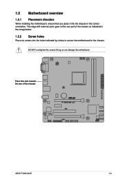
Doing so can damage the motherboard. ASUS F1A55-M LE 1-5 1.5 Motherboard overview 1.5.1 Placement direction When installing the motherboard, ensure that you place it into the holes indicated by circles to secure the motherboard to the rear part of the chassis. Place this side towards the rear of the chassis as indicated in the image below. 1.5.2 Screw holes Place six screws into the chassis in the correct orientation. The edge with external ports goes to the chassis. DO NOT overtighten the screws!
Doing so can damage the motherboard. ASUS F1A55-M LE 1-5 1.5 Motherboard overview 1.5.1 Placement direction When installing the motherboard, ensure that you place it into the holes indicated by circles to secure the motherboard to the rear part of the chassis. Place this side towards the rear of the chassis as indicated in the image below. 1.5.2 Screw holes Place six screws into the chassis in the correct orientation. The edge with external ports goes to the chassis. DO NOT overtighten the screws!
User Manual
Page 19
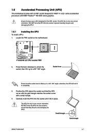
... the socket lever is lifted up to prevent bending the pins and damaging the APU! 1.6.1 Installing the APU To install a APU: 1. Small triangle Gold triangle ASUS F1A55-M LE 1-7 DO NOT force the APU into the socket to a 90°-100° angle; otherwise, the APU will not fit in place. Press the lever...
... the socket lever is lifted up to prevent bending the pins and damaging the APU! 1.6.1 Installing the APU To install a APU: 1. Small triangle Gold triangle ASUS F1A55-M LE 1-7 DO NOT force the APU into the socket to a 90°-100° angle; otherwise, the APU will not fit in place. Press the lever...
User Manual
Page 21
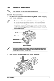
... CPU heatsink and fan: 1. Place the heatsink on the retention module base. • The retention module base is properly applied to the retention module base. 1 2 3 4 5 ASUS F1A55-M LE 1-9
... CPU heatsink and fan: 1. Place the heatsink on the retention module base. • The retention module base is properly applied to the retention module base. 1 2 3 4 5 ASUS F1A55-M LE 1-9
User Manual
Page 23
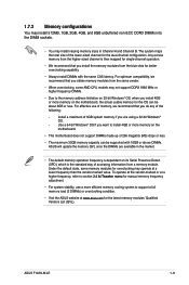
... for the latest memory modules' Qualified Vendors List (QVL). Install a maximum of the lower-sized channel for the dual-channel configuration. ASUS F1A55-M LE 1-11 For effective use a more efficient memory cooling system to the memory address limitation on 32-bit Windows® OS, when you...recommend that you install the memory modules from the blue slots for better overclocking capability. • Always install DIMMs with 16GB or above DIMMs. ASUS will update the memory QVL once the DIMMs are using a 32-bit Windows® OS. - Any excess memory from the higher-sized channel ...
... for the latest memory modules' Qualified Vendors List (QVL). Install a maximum of the lower-sized channel for the dual-channel configuration. ASUS F1A55-M LE 1-11 For effective use a more efficient memory cooling system to the memory address limitation on 32-bit Windows® OS, when you...recommend that you install the memory modules from the blue slots for better overclocking capability. • Always install DIMMs with 16GB or above DIMMs. ASUS will update the memory QVL once the DIMMs are using a 32-bit Windows® OS. - Any excess memory from the higher-sized channel ...
User Manual
Page 25
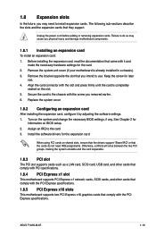
...‑sections describe the slots and the expansion cards that the cards do so may need IRQ assignments. Assign an IRQ to install expansion cards. ASUS F1A55-M LE 1-13 1.8 Expansion slots In the future, you may cause you physical injury and damage motherboard components. 1.8.1 Installing an expansion card To install an expansion card...
...‑sections describe the slots and the expansion cards that the cards do so may need IRQ assignments. Assign an IRQ to install expansion cards. ASUS F1A55-M LE 1-13 1.8 Expansion slots In the future, you may cause you physical injury and damage motherboard components. 1.8.1 Installing an expansion card To install an expansion card...

User Manual
Page 27
... audio ports in the front panel to the audio configuration table below for the function of this port becomes Front Speaker Out. 6. Microphone port (pink). ASUS F1A55-M LE 1-15 This port allows Gigabit connection to a headphone or a speaker. Line In port (light blue). Refer to support an 8-channel audio output. This port is...
... audio ports in the front panel to the audio configuration table below for the function of this port becomes Front Speaker Out. 6. Microphone port (pink). ASUS F1A55-M LE 1-15 This port allows Gigabit connection to a headphone or a speaker. Line In port (light blue). Refer to support an 8-channel audio output. This port is...

User Manual
Page 29
... intend to the Recommended Power Supply Wattage Calculator at least 15 A on +12 V and that the 20-pin power plug can provide at http://support.asus. Find the proper orientation and push down firmly until the connectors completely fit. • We recommend that you use a PSU with 20-pin and 4-pin... 300W power rating. The system may become unstable or may not boot up if the power is for your system, refer to install additional devices. ASUS F1A55-M LE 1-17
... intend to the Recommended Power Supply Wattage Calculator at least 15 A on +12 V and that the 20-pin power plug can provide at http://support.asus. Find the proper orientation and push down firmly until the connectors completely fit. • We recommend that you use a PSU with 20-pin and 4-pin... 300W power rating. The system may become unstable or may not boot up if the power is for your system, refer to install additional devices. ASUS F1A55-M LE 1-17

User Manual
Page 31
Connect the HDD Activity LED cable to this connector. LPT standardizes as a printer. 6. ASUS F1A55-M LE 1-19 System panel connector (10-1 pin F_PANEL) This connector supports several chassis-mounted functions. • System power LED (2-pin PLED) This 2-pin connector is for ...
Connect the HDD Activity LED cable to this connector. LPT standardizes as a printer. 6. ASUS F1A55-M LE 1-19 System panel connector (10-1 pin F_PANEL) This connector supports several chassis-mounted functions. • System power LED (2-pin PLED) This 2-pin connector is for ...
User Manual
Page 33
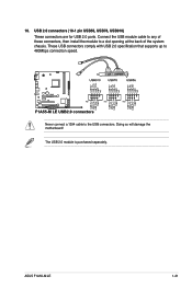
USB 2.0 connectors (10-1 pin USB56, USB78, USB910) These connectors are for USB 2.0 ports. Never connect a 1394 cable to a slot opening at the back of these connectors, then install the module to the USB connectors. Connect the USB module cable to any of the system chassis. Doing so will damage the motherboard! The USB 2.0 module is purchased separately. These USB connectors comply with USB 2.0 specification that supports up to 480Mbps connection speed. 10. ASUS F1A55-M LE 1-21
USB 2.0 connectors (10-1 pin USB56, USB78, USB910) These connectors are for USB 2.0 ports. Never connect a 1394 cable to a slot opening at the back of these connectors, then install the module to the USB connectors. Connect the USB module cable to any of the system chassis. Doing so will damage the motherboard! The USB 2.0 module is purchased separately. These USB connectors comply with USB 2.0 specification that supports up to 480Mbps connection speed. 10. ASUS F1A55-M LE 1-21
User Manual
Page 36
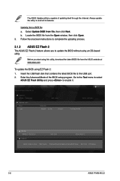
... Exit DATE: 06/23/2011 F1A55MLE.ROM File Info MODEL: F1A55-M LE Help Info VER: 0203 DATE: 06/23/11 [Enter] Select or Load [Tab] Switch [Up/Down/PageUp/PageDown/Home/End] Move [Esc] Exit [F2] Backup 2-2 ASUS F1A55-M LE Always update the utility to enable it. Select Update BIOS from... the ASUS website at www.asus.com. Insert the USB flash disk that contains the latest BIOS file to update the BIOS without using...
... Exit DATE: 06/23/2011 F1A55MLE.ROM File Info MODEL: F1A55-M LE Help Info VER: 0203 DATE: 06/23/11 [Enter] Select or Load [Tab] Switch [Up/Down/PageUp/PageDown/Home/End] Move [Esc] Exit [F2] Backup 2-2 ASUS F1A55-M LE Always update the utility to enable it. Select Update BIOS from... the ASUS website at www.asus.com. Insert the USB flash disk that contains the latest BIOS file to update the BIOS without using...
User Manual
Page 38
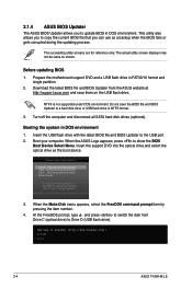
... BIOS file and BIOS Updater to FreeDOS (http://www.freedos.org)! Do not save them on the USB flash drive. C:\>d: D:\> 2-4 ASUS F1A55-M LE The succeeding utility screens are for reference only. Turn off the computer and disconnect all SATA hard disk drives (optional). Insert the support ... the BIOS fails or gets corrupted during the updating process. Before updating BIOS 1. NTFS is not supported under DOS environment. 2.1.4 ASUS BIOS Updater The ASUS BIOS Updater allows you to copy the current BIOS file that you to update BIOS in DOS environment. Download the latest BIOS file...
... BIOS file and BIOS Updater to FreeDOS (http://www.freedos.org)! Do not save them on the USB flash drive. C:\>d: D:\> 2-4 ASUS F1A55-M LE The succeeding utility screens are for reference only. Turn off the computer and disconnect all SATA hard disk drives (optional). Insert the support ... the BIOS fails or gets corrupted during the updating process. Before updating BIOS 1. NTFS is not supported under DOS environment. 2.1.4 ASUS BIOS Updater The ASUS BIOS Updater allows you to copy the current BIOS file that you to update BIOS in DOS environment. Download the latest BIOS file...

User Manual
Page 40
... the BIOS file and press . Are you sure to confirm BIOS update. Refer to section 2.9 Exit menu for DOS V1.07 Current ROM BOARD: F1A55-M LE VER: 0203 DATE: 06/23/2011 Update ROM BOARD: Unknown VER: Unknown DATE: Unknown PATH: A:\ A: F1A55MLE.ROM 4194304 2011-06-23 17:...the BIOS file if you to update BIOS? Yes No 4. BIOS Updater checks the selected BIOS file and prompts you have disconnected them. 2-6 ASUS F1A55-M LE D:\>bupdater /pc /g 2. The BIOS Updater screen appears as below. Select Yes and press . Select the Load Optimized Defaults item under the Exit menu...
... the BIOS file and press . Are you sure to confirm BIOS update. Refer to section 2.9 Exit menu for DOS V1.07 Current ROM BOARD: F1A55-M LE VER: 0203 DATE: 06/23/2011 Update ROM BOARD: Unknown VER: Unknown DATE: Unknown PATH: A:\ A: F1A55MLE.ROM 4194304 2011-06-23 17:...the BIOS file if you to update BIOS? Yes No 4. BIOS Updater checks the selected BIOS file and prompts you have disconnected them. 2-6 ASUS F1A55-M LE D:\>bupdater /pc /g 2. The BIOS Updater screen appears as below. Select Yes and press . Select the Load Optimized Defaults item under the Exit menu...
User Manual
Page 42
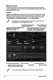
...in the EZ Mode/Advanced Mode screen. To access the Advanced Mode, click Exit/Advanced Mode, then select Advanced Mode. EZ Mode Tuesday [1/1/2008] F1A55-M LE BIOS Version : 0203 CPU Type : AMD Engineering Sample Total Memory : 1024 MB (DDR3 1333MHz) Exit/Advanced Mode Build Date : 06/23/...248V Q-Fan Control Quiet Performance Boot Priority Energy Saving Normal Use the mouse to drag or keyboard to navigate to the system. 2-8 ASUS F1A55-M LE Refer to display all fan speeds if available Displays the CPU/motherboard temperature, CPU/5V/3.3V/12V voltage output, CPU/chassis fan speed ...
...in the EZ Mode/Advanced Mode screen. To access the Advanced Mode, click Exit/Advanced Mode, then select Advanced Mode. EZ Mode Tuesday [1/1/2008] F1A55-M LE BIOS Version : 0203 CPU Type : AMD Engineering Sample Total Memory : 1024 MB (DDR3 1333MHz) Exit/Advanced Mode Build Date : 06/23/...248V Q-Fan Control Quiet Performance Boot Priority Energy Saving Normal Use the mouse to drag or keyboard to navigate to the system. 2-8 ASUS F1A55-M LE Refer to display all fan speeds if available Displays the CPU/motherboard temperature, CPU/5V/3.3V/12V voltage output, CPU/chassis fan speed ...
User Manual
Page 44
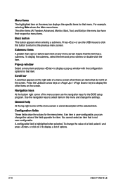
... right side of a field, select it and press or click on it to select items in the menu and change the value of options. 2-10 ASUS F1A55-M LE A configurable field is user-configurable, you can change the settings. Menu items The highlighted item on the menu bar displays the specific items for that...
... right side of a field, select it and press or click on it to select items in the menu and change the value of options. 2-10 ASUS F1A55-M LE A configurable field is user-configurable, you can change the settings. Menu items The highlighted item on the menu bar displays the specific items for that...
User Manual
Page 46
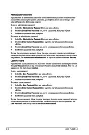
Confirm the password when prompted. After you clear the password, the User Password item on top of the screen shows Not Installed. 2-12 ASUS F1A55-M LE From the Create New Password box, key in the current password, then press . 3. From the Enter Current Password box, key in a password, then press . 3. Confirm ...
Confirm the password when prompted. After you clear the password, the User Password item on top of the screen shows Not Installed. 2-12 ASUS F1A55-M LE From the Create New Password box, key in the current password, then press . 3. From the Enter Current Password box, key in a password, then press . 3. Confirm ...
User Manual
Page 48
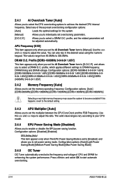
... set overclocking parameters. [D.O.C.P.] Allows you to set the Ai Overclock Tuner item to select a DRAM O.C. profile, which applies different settings to start automatic overclocking. 2-14 ASUS F1A55-M LE Configuration options: [Auto] [Light Power Saving Mode] [Medium Power Saving Mode] [Max Power Saving Mode] 2.4.5 OC Tuner OC Tuner automatically overclocks the frequency and voltage...
... set overclocking parameters. [D.O.C.P.] Allows you to set the Ai Overclock Tuner item to select a DRAM O.C. profile, which applies different settings to start automatic overclocking. 2-14 ASUS F1A55-M LE Configuration options: [Auto] [Light Power Saving Mode] [Medium Power Saving Mode] [Max Power Saving Mode] 2.4.5 OC Tuner OC Tuner automatically overclocks the frequency and voltage...
User Manual
Page 50
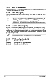
... better overclocking performance, but increase the CPU and VRM thermal. The CPU working voltage will decrease proportionally to set this function for EMI control. 2-16 ASUS F1A55-M LE 2.4.11 APU1.2V Voltage [Auto] Allows you to set the VDDA voltage. The values range from 2.5000V to 2.8000V with a 0.01V interval. 2.4.12 VDDA Voltage...
... better overclocking performance, but increase the CPU and VRM thermal. The CPU working voltage will decrease proportionally to set this function for EMI control. 2-16 ASUS F1A55-M LE 2.4.11 APU1.2V Voltage [Auto] Allows you to set the VDDA voltage. The values range from 2.5000V to 2.8000V with a 0.01V interval. 2.4.12 VDDA Voltage...
User Manual
Page 52
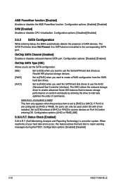
... the order of your hard disk errors occur, this feature allows the hard disk to [IDE] instead of SATA devices. Configuration options: [Enabled] [Disabled] 2-18 ASUS F1A55-M LE AMD PowerNow function [Enabled] Enables or disables the AMD PowerNow function. Set to report warning messages during the POST. Configuration options: [Enabled] [Disabled] SVM [Enabled...
... the order of your hard disk errors occur, this feature allows the hard disk to [IDE] instead of SATA devices. Configuration options: [Enabled] [Disabled] 2-18 ASUS F1A55-M LE AMD PowerNow function [Enabled] Enables or disables the AMD PowerNow function. Set to report warning messages during the POST. Configuration options: [Enabled] [Disabled] SVM [Enabled...


