
User Guide
Page 4
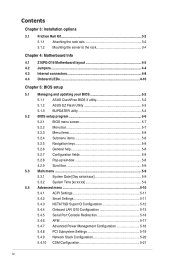
Contents Chapter 3: Installation options 3.1 Friction Rail Kit 3-2 3.1.1 Attaching the rack rails 3-2 3.1.2 Mounting the server to the rack 3-4 Chapter 4: Motherboard Info 4.1 Z10PG-D16 Motherboard layout 4-2 4.2 Jumpers...4-4 4.3 Internal connectors 4-8 4.4 Onboard LEDs 4-16 Chapter 5: BIOS setup 5.1 Managing and updating your BIOS 5-2 5.1.1 ASUS CrashFree BIOS 3 utility 5-2 5.1.2 ASUS EZ Flash Utility 5-3 5.1.3 BUPDATER utility 5-4 5.2 BIOS setup program 5-6 5.2.1 BIOS menu screen...
Contents Chapter 3: Installation options 3.1 Friction Rail Kit 3-2 3.1.1 Attaching the rack rails 3-2 3.1.2 Mounting the server to the rack 3-4 Chapter 4: Motherboard Info 4.1 Z10PG-D16 Motherboard layout 4-2 4.2 Jumpers...4-4 4.3 Internal connectors 4-8 4.4 Onboard LEDs 4-16 Chapter 5: BIOS setup 5.1 Managing and updating your BIOS 5-2 5.1.1 ASUS CrashFree BIOS 3 utility 5-2 5.1.2 ASUS EZ Flash Utility 5-3 5.1.3 BUPDATER utility 5-4 5.2 BIOS setup program 5-6 5.2.1 BIOS menu screen...

User Guide
Page 5
... 5-28 5.5.3 Common RefCode Configuration 5-30 5.5.4 QPI Configuration 5-30 5.5.5 Memory Configuration 5-31 5.5.6 IIO Configuration 5-34 5.5.7 PCH Configuration 5-35 5.5.8 Miscellaneous Configuration 5-37 5.5.9 Server ME Configuration 5-38 5.5.10 Runtime Error Logging Support 5-38 5.6 Server Mgmt menu 5-39 5.7 Event Logs menu 5-43 5.7.1 Change Smbios Event Log Settings 5-43 5.7.2 View Smbios Event Log 5-43 5.8 Monitor menu 5-44...
... 5-28 5.5.3 Common RefCode Configuration 5-30 5.5.4 QPI Configuration 5-30 5.5.5 Memory Configuration 5-31 5.5.6 IIO Configuration 5-34 5.5.7 PCH Configuration 5-35 5.5.8 Miscellaneous Configuration 5-37 5.5.9 Server ME Configuration 5-38 5.5.10 Runtime Error Logging Support 5-38 5.6 Server Mgmt menu 5-39 5.7 Event Logs menu 5-43 5.7.1 Change Smbios Event Log Settings 5-43 5.7.2 View Smbios Event Log 5-43 5.8 Monitor menu 5-44...

User Guide
Page 9
...or equivalent type recommended by certified or experienced engineers. • Before operating the server, carefully read all the manuals included with the server package. • Before using the server, ensure all cables are correctly connected and the power cables are connected. ix ... and temperature extremes. This product is incorrectly replaced. Danger of used batteries according to avoid electrical shock. Place the server on this server must be conducted by the manufacturer. Dispose of explosion if battery is equipped with a properly grounded electrical outlet to the...
...or equivalent type recommended by certified or experienced engineers. • Before operating the server, carefully read all the manuals included with the server package. • Before using the server, ensure all cables are correctly connected and the power cables are connected. ix ... and temperature extremes. This product is incorrectly replaced. Danger of used batteries according to avoid electrical shock. Place the server on this server must be conducted by the manufacturer. Dispose of explosion if battery is equipped with a properly grounded electrical outlet to the...

User Guide
Page 10
...motherboard layout, jumper settings, and connector locations. 5. Chapter 1: Product Introduction This chapter describes the general features of configuring a server. Chapter 5: BIOS setup This chapter tells how to perform when installing or removing system components. 3. Chapter 6: RAID configuration ...This chapter tells how to install optional components into the barebone server. 4. About this guide Audience This user guide is intended for different system components. Detailed descriptions of the BIOS parameters...
...motherboard layout, jumper settings, and connector locations. 5. Chapter 1: Product Introduction This chapter describes the general features of configuring a server. Chapter 5: BIOS setup This chapter tells how to perform when installing or removing system components. 3. Chapter 6: RAID configuration ...This chapter tells how to install optional components into the barebone server. 4. About this guide Audience This user guide is intended for different system components. Detailed descriptions of the BIOS parameters...
User Guide
Page 11
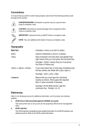
... to help you MUST follow to the following symbols used throughout this manual. Used to set up and use the proprietary ASUS server management utility. 2. ASUS Server Web-based Management (ASWM) user guide This manual tells how to emphasize a word or a phrase. Keys enclosed in ...simultaneously, the key names are linked with a plus sign (+). Example: ++ Means that you must press the enclosed key. ASUS websites The ASUS websites worldwide provide updated information for product and software updates. 1. If you perform certain tasks properly, take note of the ...
... to help you MUST follow to the following symbols used throughout this manual. Used to set up and use the proprietary ASUS server management utility. 2. ASUS Server Web-based Management (ASWM) user guide This manual tells how to emphasize a word or a phrase. Keys enclosed in ...simultaneously, the key names are linked with a plus sign (+). Example: ++ Means that you must press the enclosed key. ASUS websites The ASUS websites worldwide provide updated information for product and software updates. 1. If you perform certain tasks properly, take note of the ...
User Guide
Page 14
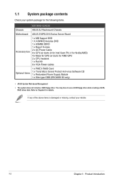
...Kit 8 x VGA Power cables Optional Items 1 x PIKE II RAID Card 1 x Trend Micro Server Protect Anti-virus Software CD 1 x Redundant Power Supply Module 1 x Slim-type ODD (ESC4000 G3 only) • ASUS System Web-based Management • The system does not include a USB floppy drive. 1.1 System ...driver disk. If any of the above items is damaged or missing, contact your system package for the following items. ESC4000 G3/G3S Chassis ASUS 2U Rackmount Chassis Motherboard ASUS Z10PG-D16 Series Server Board Accessory box 1 x MB Support DVD 1 X ASWM Enterprise DVD 1 x ASMB8 SDVD 1 x Bag of...
...Kit 8 x VGA Power cables Optional Items 1 x PIKE II RAID Card 1 x Trend Micro Server Protect Anti-virus Software CD 1 x Redundant Power Supply Module 1 x Slim-type ODD (ESC4000 G3 only) • ASUS System Web-based Management • The system does not include a USB floppy drive. 1.1 System ...driver disk. If any of the above items is damaged or missing, contact your system package for the following items. ESC4000 G3/G3S Chassis ASUS 2U Rackmount Chassis Motherboard ASUS Z10PG-D16 Series Server Board Accessory box 1 x MB Support DVD 1 X ASWM Enterprise DVD 1 x ASMB8 SDVD 1 x Bag of...

User Guide
Page 16
... II 3108 8-port SAS 12G HW RAID card * Support with the PCI-E riser card. * Please refer to www.asus.com for Windows only; 1.3 System specifications The ASUS ESC4000 G3/G3S Series servers features the ASUS Z10PG-D16 Series server board that supports Intel® LGA 2011-3 Xeon® processor from the E5-2600 V3 product family. Model Name...
... II 3108 8-port SAS 12G HW RAID card * Support with the PCI-E riser card. * Please refer to www.asus.com for Windows only; 1.3 System specifications The ASUS ESC4000 G3/G3S Series servers features the ASUS Z10PG-D16 Series server board that supports Intel® LGA 2011-3 Xeon® processor from the E5-2600 V3 product family. Model Name...

User Guide
Page 17
... update. (continued on the next page) ASUS ESC4000 G3/G3S Series 1-5 System specifications Model Name ESC4000 G3 HDD Bays I /O 3 x RJ-45 ports (One for ASMB8-iKVM) 4 x USB ports (2 x Front USB 2.0 , 2 x Rear USB 3.0) 1 x VGA Port Windows® Server 2012 R2 Windows® Server 2012 Windows® Server 2008 Enterprise R2 SP1 Windows® Server 2008 Enterprise SP2 OS Support RedHat®...
... update. (continued on the next page) ASUS ESC4000 G3/G3S Series 1-5 System specifications Model Name ESC4000 G3 HDD Bays I /O 3 x RJ-45 ports (One for ASMB8-iKVM) 4 x USB ports (2 x Front USB 2.0 , 2 x Rear USB 3.0) 1 x VGA Port Windows® Server 2012 R2 Windows® Server 2012 Windows® Server 2008 Enterprise R2 SP1 Windows® Server 2008 Enterprise SP2 OS Support RedHat®...
User Guide
Page 18
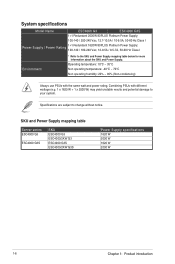
... below for more information about the SKU and Power Supply. SKU and Power Supply mapping table Server series ESC4000 G3 ESC4000 G3S SKU ESC4000 G3 ESC4000/2KW G3 ESC4000 G3S ESC4000/2KW G3S Power Supply specifications 1620 W 2000 W 1620 W 2000 W 1-6 Chapter 1: Product introduction System specifications Model Name ESC4000 G3 ESC4000 G3S 1+1 Redundant 2000W 80PLUS Platinum Power Supply; 100-140 / 200-240 Vac, 12.7-10.5A / 10-9.5A...
... below for more information about the SKU and Power Supply. SKU and Power Supply mapping table Server series ESC4000 G3 ESC4000 G3S SKU ESC4000 G3 ESC4000/2KW G3 ESC4000 G3S ESC4000/2KW G3S Power Supply specifications 1620 W 2000 W 1620 W 2000 W 1-6 Chapter 1: Product introduction System specifications Model Name ESC4000 G3 ESC4000 G3S 1+1 Redundant 2000W 80PLUS Platinum Power Supply; 100-140 / 200-240 Vac, 12.7-10.5A / 10-9.5A...
User Guide
Page 19
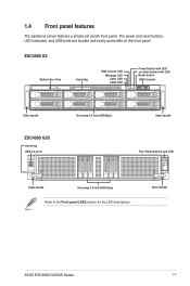
1.4 Front panel features The barebone server features a simple yet stylish front panel. Steel handle ASUS ESC4000 G3/G3S Series 1-7 The power and reset buttons, LED indicators, and USB ports are located and easily accessible on the front panel. ESC4000 G3 Optical disc drive Asset tag HDD Access LED Message LED LAN1 LED LAN2 LED 21 Power button with...
1.4 Front panel features The barebone server features a simple yet stylish front panel. Steel handle ASUS ESC4000 G3/G3S Series 1-7 The power and reset buttons, LED indicators, and USB ports are located and easily accessible on the front panel. ESC4000 G3 Optical disc drive Asset tag HDD Access LED Message LED LAN1 LED LAN2 LED 21 Power button with...

User Guide
Page 20
... port 1 LAN port 2 4 Full-length Expansion slots Power cord connector and Redundant power supply 4 Full-length Expansion slots • The rear I /O shield with openings for ASUS ASMB8-iKVM controller only. 1-8 Chapter 1: Product introduction The middle part includes the I /O ports do not appear on the rear panel of the...
... port 1 LAN port 2 4 Full-length Expansion slots Power cord connector and Redundant power supply 4 Full-length Expansion slots • The rear I /O shield with openings for ASUS ASMB8-iKVM controller only. 1-8 Chapter 1: Product introduction The middle part includes the I /O ports do not appear on the rear panel of the...
User Guide
Page 21
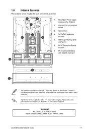
... backplane (hidden) 5. PCI-E Expansion Boards (hidden) 7. PCI-E x24 slot (hidden) with butterfly riser card The barebone server does not include a floppy disk drive or an optical dirve. Please remove the protection film before shipping. Redundant Power supply ...WARNING HAZARDOUS MOVING PARTS KEEP FINGERS AND OTHER BODY PARTS AWAY ASUS ESC4000 G3/G3S Series 1-9 A protection film is pre-attached to use a floppy disk. 1.6 Internal features The barebone server includes the basic components as shown. 1. System fans 4. ASUS Z10PG-D16 Server Board 3. Hot-swap HDD tray (SAS and SATA) ...
... backplane (hidden) 5. PCI-E Expansion Boards (hidden) 7. PCI-E x24 slot (hidden) with butterfly riser card The barebone server does not include a floppy disk drive or an optical dirve. Please remove the protection film before shipping. Redundant Power supply ...WARNING HAZARDOUS MOVING PARTS KEEP FINGERS AND OTHER BODY PARTS AWAY ASUS ESC4000 G3/G3S Series 1-9 A protection film is pre-attached to use a floppy disk. 1.6 Internal features The barebone server includes the basic components as shown. 1. System fans 4. ASUS Z10PG-D16 Server Board 3. Hot-swap HDD tray (SAS and SATA) ...

User Guide
Page 38
... 32 GB RDIMMs or 32 GB or 64 GB LR-DIMMs into the DIMM sockets using the memory configurations in this section. • Refer to ASUS Server AVL for the updated list of compatible DIMMs. • When installing only one DIMM in a single CPU configuration, install the DIMM on either A1 or...
... 32 GB RDIMMs or 32 GB or 64 GB LR-DIMMs into the DIMM sockets using the memory configurations in this section. • Refer to ASUS Server AVL for the updated list of compatible DIMMs. • When installing only one DIMM in a single CPU configuration, install the DIMM on either A1 or...

User Guide
Page 56
.... Refer to your system. • For a steady power input, use PSUs with the same watt and power rating. The combined output power varies with the server system package. 2-28 Chapter 2: Hardware setup Output Power (Watt) per PSU 1100W 1400W 1800W 1980W 2000W • To enable the hot-swap feature (redundant mode...
.... Refer to your system. • For a steady power input, use PSUs with the same watt and power rating. The combined output power varies with the server system package. 2-28 Chapter 2: Hardware setup Output Power (Watt) per PSU 1100W 1400W 1800W 1980W 2000W • To enable the hot-swap feature (redundant mode...

User Guide
Page 60
... front of the accelerator bracket into the card slot on the slot. 16. Repeat step 4-13 if you need to install a second accelerator to the server chassis with two screws. 2-32 Chapter 2: Hardware setup
... front of the accelerator bracket into the card slot on the slot. 16. Repeat step 4-13 if you need to install a second accelerator to the server chassis with two screws. 2-32 Chapter 2: Hardware setup

User Guide
Page 61
Chapter 3: Installation options Installation options This chapter describes how to install the optional components and devices into the barebone server. 3
Chapter 3: Installation options Installation options This chapter describes how to install the optional components and devices into the barebone server. 3

User Guide
Page 62
Refer to the sides of the server using the set of latch screws. The locations of screws Latch screws Rail Washers Rail screws Friction rack rails Front end Rack rails Rear end 3.1.1 Attaching the rack rails To install the Friction Rail Kit: 1. Secure the two fixing latches to your server user manual for details. 3-2 Chapter 3: Installation options 3.1 Friction Rail Kit The rail kit package includes: Fixing latches Set of the screw holes vary with different server models.
Refer to the sides of the server using the set of latch screws. The locations of screws Latch screws Rail Washers Rail screws Friction rack rails Front end Rack rails Rear end 3.1.1 Attaching the rack rails To install the Friction Rail Kit: 1. Secure the two fixing latches to your server user manual for details. 3-2 Chapter 3: Installation options 3.1 Friction Rail Kit The rail kit package includes: Fixing latches Set of the screw holes vary with different server models.

User Guide
Page 64
ESC4000 G3 side knots steel handle steel handle ESC4000 G3S side knots Fixing latches steel handle steel handle 3-4 Fixing latches Chapter 3: Installation options 3.1.2 Mounting the server to the rack To mount the server to the rack, align the server rails with the rack rails, then push the server all the way to the depth of the rack. * Ensure to include the side knots on the sides of the server when mounting the server to the rack rail holders. * Use the steel handle when mounting the server to the rack.
ESC4000 G3 side knots steel handle steel handle ESC4000 G3S side knots Fixing latches steel handle steel handle 3-4 Fixing latches Chapter 3: Installation options 3.1.2 Mounting the server to the rack To mount the server to the rack, align the server rails with the rack rails, then push the server all the way to the depth of the rack. * Ensure to include the side knots on the sides of the server when mounting the server to the rack rail holders. * Use the steel handle when mounting the server to the rack.

User Guide
Page 65
To unmount the server to the rack: Gently pull the server from the rack. • Press the fixing latches on both sides to release the server from the rack. • Use the steel handle when unmounting the server to the rack. ASUS ESC4000 G3/G3S Series 3-5
To unmount the server to the rack: Gently pull the server from the rack. • Press the fixing latches on both sides to release the server from the rack. • Use the steel handle when unmounting the server to the rack. ASUS ESC4000 G3/G3S Series 3-5

User Guide
Page 67
This chapter includes the motherboard layout, jumper settings, and connector locations. 4 Chapter 4: Motherboard Info Motherboard Info This chapter gives information about the motherboard that comes with the server.
This chapter includes the motherboard layout, jumper settings, and connector locations. 4 Chapter 4: Motherboard Info Motherboard Info This chapter gives information about the motherboard that comes with the server.
