

User Guide
Page 1
B85M-G PLUS Motherboard
B85M-G PLUS Motherboard
User Guide
Page 3
Contents Safety information...iv About this guide...iv Package contents...vi B85M-G PLUS specifications summary vi Chapter 1: Product introduction 1.1 Before you proceed 1-1 1.2 Motherboard overview 1-1 1.3 Central Processing Unit (CPU 1-3 1.4 System memory 1-7 1.5 Expansion slots 1-9 1.6 Jumpers...1-11 1.7 Connectors 1-12 1.8 Software support 1-21 Chapter 2: BIOS information 2.1 Managing... menu 2-13 2.6 Advanced menu 2-22 2.7 Monitor menu 2-31 2.8 Boot menu 2-34 2.9 Tools menu 2-40 2.10 Exit menu...2-41 Appendices Notices...A-1 ASUS contact information A-4 iii
Contents Safety information...iv About this guide...iv Package contents...vi B85M-G PLUS specifications summary vi Chapter 1: Product introduction 1.1 Before you proceed 1-1 1.2 Motherboard overview 1-1 1.3 Central Processing Unit (CPU 1-3 1.4 System memory 1-7 1.5 Expansion slots 1-9 1.6 Jumpers...1-11 1.7 Connectors 1-12 1.8 Software support 1-21 Chapter 2: BIOS information 2.1 Managing... menu 2-13 2.6 Advanced menu 2-22 2.7 Monitor menu 2-31 2.8 Boot menu 2-34 2.9 Tools menu 2-40 2.10 Exit menu...2-41 Appendices Notices...A-1 ASUS contact information A-4 iii
User Guide
Page 4
...contains the information you detect any area where it may be exposed to moisture. • Place the product on the motherboard. • Chapter 2: BIOS information This chapter discusses changing system settings through the BIOS Setup menus. Operation safety • Before installing the..., disconnect all power cables from the existing system before you add a device. • Before connecting or removing signal cables from the motherboard, ensure that the power cables for the devices are unplugged before using the product, ensure all cables are correctly connected and the power cables...
...contains the information you detect any area where it may be exposed to moisture. • Place the product on the motherboard. • Chapter 2: BIOS information This chapter discusses changing system settings through the BIOS Setup menus. Operation safety • Before installing the..., disconnect all power cables from the existing system before you add a device. • Before connecting or removing signal cables from the motherboard, ensure that the power cables for the devices are unplugged before using the product, ensure all cables are correctly connected and the power cables...

User Guide
Page 6
... Intel® Extreme Memory Profile (XMP) * Hyper DIMM support is damaged or missing, contact your motherboard package for the following items. Motherboard Cables Accessories Application DVD Documentation ASUS B85M-G PLUS motherboard 2 x Serial ATA 6.0 Gb/s cables 1 x I/O Shield Support DVD User Guide If any of... higher memory modules on the CPU types. ** Refer to www.asus.com for Intel® CPU support list. resolution of 1920 x 1200 @60Hz - Supports D-Sub with max. B85M-G PLUS specifications summary CPU Chipset Memory Graphics Expansion slots Storage LAN LGA1150 socket...
... Intel® Extreme Memory Profile (XMP) * Hyper DIMM support is damaged or missing, contact your motherboard package for the following items. Motherboard Cables Accessories Application DVD Documentation ASUS B85M-G PLUS motherboard 2 x Serial ATA 6.0 Gb/s cables 1 x I/O Shield Support DVD User Guide If any of... higher memory modules on the CPU types. ** Refer to www.asus.com for Intel® CPU support list. resolution of 1920 x 1200 @60Hz - Supports D-Sub with max. B85M-G PLUS specifications summary CPU Chipset Memory Graphics Expansion slots Storage LAN LGA1150 socket...

User Guide
Page 9
... the power cord from the power supply. Do not overtighten the screws! ASUS B85M-G PLUS 1-1 Failure to avoid touching the ICs on them due to static electricity. • Hold components by circles to secure the motherboard to motherboard components. 1.2.1 Placement direction When installing the motherboard, place it on a grounded antistatic pad or in the correct orientation.
... the power cord from the power supply. Do not overtighten the screws! ASUS B85M-G PLUS 1-1 Failure to avoid touching the ICs on them due to static electricity. • Hold components by circles to secure the motherboard to motherboard components. 1.2.1 Placement direction When installing the motherboard, place it on a grounded antistatic pad or in the correct orientation.

User Guide
Page 10
...F_PANEL SATA3G_1 CLRTC SATA6G_4 SATA3G_2 7 AAFP 16 15 14 13 12 11 10 9 8 Chapter 1: Product introduction Place this side towards the rear of the chassis B85M-G PLUS 1.2.3 Motherboard layout 1 2 19.3cm(7.6in) 3 4 KBMS CHA_FAN2 DIGI +VRM CPU_FAN ATX12V DVI VGA DDR3 DIMM_A1 (64bit, 240-pin module) DDR3 DIMM_A2 (64bit, ...) EATXPWR 1-2 USB910 USB3_56 LGA1150 1 HDMI ASM 1442K 23.4cm(9.2in) LAN_USB34 CHA_FAN1 USB3_12 BATTERY 5 AUDIO SATA6G_3 SATA6G_2 SATA6G_1 PCIEX16 Realtek 8111GR B85M-G PLUS Super I/O PCIEX1_1 PCIEX1_2 64Mb BIOS 6 Intel® B85 ALC 887-
...F_PANEL SATA3G_1 CLRTC SATA6G_4 SATA3G_2 7 AAFP 16 15 14 13 12 11 10 9 8 Chapter 1: Product introduction Place this side towards the rear of the chassis B85M-G PLUS 1.2.3 Motherboard layout 1 2 19.3cm(7.6in) 3 4 KBMS CHA_FAN2 DIGI +VRM CPU_FAN ATX12V DVI VGA DDR3 DIMM_A1 (64bit, 240-pin module) DDR3 DIMM_A2 (64bit, ...) EATXPWR 1-2 USB910 USB3_56 LGA1150 1 HDMI ASM 1442K 23.4cm(9.2in) LAN_USB34 CHA_FAN1 USB3_12 BATTERY 5 AUDIO SATA6G_3 SATA6G_2 SATA6G_1 PCIEX16 Realtek 8111GR B85M-G PLUS Super I/O PCIEX1_1 PCIEX1_2 64Mb BIOS 6 Intel® B85 ALC 887-

User Guide
Page 11
... 1-7 1-18 1-17 1-11 1-17 1-19 1-16 1-18 1-14 1-20 1-15 1-15 1-19 1.3 Central Processing Unit (CPU) This motherboard comes with a surface mount LGA1150 socket designed for the 4th Generation and New 4th Generation Intel® Core™ i7 / Core™ i5 ...174; LGA1150 CPU socket 4. CPU and chassis fan connectors (4-pin CPU_FAN, 4-pin CHA_FAN1/2) 3. Chassis intrusion connector (4-1 pin CHASSIS) 14. B85M-G PLUS B85M-G PLUS CPU socket LGA1150 ASUS B85M-G PLUS 1-3 ATX power connectors (24-pin EATXPWR, 4-pin ATX12V) 2. USB 3.0 connector (20-1 pin USB3_12) 6. Front panel audio connector (...
... 1-7 1-18 1-17 1-11 1-17 1-19 1-16 1-18 1-14 1-20 1-15 1-15 1-19 1.3 Central Processing Unit (CPU) This motherboard comes with a surface mount LGA1150 socket designed for the 4th Generation and New 4th Generation Intel® Core™ i7 / Core™ i5 ...174; LGA1150 CPU socket 4. CPU and chassis fan connectors (4-pin CPU_FAN, 4-pin CHA_FAN1/2) 3. Chassis intrusion connector (4-1 pin CHASSIS) 14. B85M-G PLUS B85M-G PLUS CPU socket LGA1150 ASUS B85M-G PLUS 1-3 ATX power connectors (24-pin EATXPWR, 4-pin ATX12V) 2. USB 3.0 connector (20-1 pin USB3_12) 6. Front panel audio connector (...

User Guide
Page 12
... if you see any damage to the PnP cap/socket contacts/motherboard components. • Keep the cap after installing the motherboard. Unplug all power cables before installing the CPU. • Upon purchase of the PnP cap. 1.3.1 Installing the CPU 1 A B 2 3 1-4 Chapter 1: Product introduction ASUS will process Return Merchandise Authorization (RMA) requests only if the...
... if you see any damage to the PnP cap/socket contacts/motherboard components. • Keep the cap after installing the motherboard. Unplug all power cables before installing the CPU. • Upon purchase of the PnP cap. 1.3.1 Installing the CPU 1 A B 2 3 1-4 Chapter 1: Product introduction ASUS will process Return Merchandise Authorization (RMA) requests only if the...

User Guide
Page 15
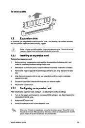
... DDR3 1600MHz and higher memory modules on the motherboard, the actual usable memory for single-channel operation. • Due to install 4GB or more memory on XMP mode will run at the maximum transfer rate of the following: - ASUS B85M-G PLUS 1-7 DDR3 modules are using a 32-bit ... Use a maximum of the DDR3 DIMM sockets: DIMM_A1 DIMM_A2 DIMM_B1 DIMM_B2 Channel Channel A Channel B Sockets DIMM_A1 & DIMM_A2 DIMM_B1 & DIMM_B2 B85M-G PLUS B85M-G PLUS 240-pin DDR3 DIMM sockets 1.4.2 Memory configurations You may install 1GB, 2GB, 4GB, and 8GB unbuffered non-ECC DDR3 DIMMs into the ...
... DDR3 1600MHz and higher memory modules on the motherboard, the actual usable memory for single-channel operation. • Due to install 4GB or more memory on XMP mode will run at the maximum transfer rate of the following: - ASUS B85M-G PLUS 1-7 DDR3 modules are using a 32-bit ... Use a maximum of the DDR3 DIMM sockets: DIMM_A1 DIMM_A2 DIMM_B1 DIMM_B2 Channel Channel A Channel B Sockets DIMM_A1 & DIMM_A2 DIMM_B1 & DIMM_B2 B85M-G PLUS B85M-G PLUS 240-pin DDR3 DIMM sockets 1.4.2 Memory configurations You may install 1GB, 2GB, 4GB, and 8GB unbuffered non-ECC DDR3 DIMMs into the ...
User Guide
Page 17
...8209;sections describe the slots and the expansion cards that you intend to the card. 3. Remove the system unit cover (if your motherboard is completely seated on shared slots, ensure that the drivers support "Share IRQ" or that came with it by adjusting the software ... card, configure it and make the necessary hardware settings for information on the system and change the necessary BIOS settings, if any. ASUS B85M-G PLUS 1-9 Otherwise, conflicts will arise between the two PCI groups, making the system unstable and the card inoperable. Install the software drivers ...
...8209;sections describe the slots and the expansion cards that you intend to the card. 3. Remove the system unit cover (if your motherboard is completely seated on shared slots, ensure that the drivers support "Share IRQ" or that came with it by adjusting the software ... card, configure it and make the necessary hardware settings for information on the system and change the necessary BIOS settings, if any. ASUS B85M-G PLUS 1-9 Otherwise, conflicts will arise between the two PCI groups, making the system unstable and the card inoperable. Install the software drivers ...

User Guide
Page 18
....0_1 USB2.0_2 XHCI HD AUDIO PCIE_X16_1 PCIE_X1_1 PCIE_X1_2 A B CDE F G H - - shared - - - - - - 1-10 Chapter 1: Product introduction shared - - - - - - - - - - - shared - - - - - - - shared - - - - - - - - shared - shared - - - - - - - - 1.5.3 PCI Express 2.0 x1 slots This motherboard supports PCI Express x1 network cards, SCSI cards, and other cards that comply with the PCI Express specifications. 1.5.4 PCI Express 3.0/2.0 x16 slot This...
....0_1 USB2.0_2 XHCI HD AUDIO PCIE_X16_1 PCIE_X1_1 PCIE_X1_2 A B CDE F G H - - shared - - - - - - 1-10 Chapter 1: Product introduction shared - - - - - - - - - - - shared - - - - - - - shared - - - - - - - - shared - shared - - - - - - - - 1.5.3 PCI Express 2.0 x1 slots This motherboard supports PCI Express x1 network cards, SCSI cards, and other cards that comply with the PCI Express specifications. 1.5.4 PCI Express 3.0/2.0 x16 slot This...
User Guide
Page 23
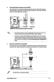
...standard. See section 2.6.7 Onboard Devices Configuration for a serial (COM) port. By default, this connector, then install the module to [HD]. ASUS B85M-G PLUS 1-15 Connect the serial port module cable to this connector is for details. 4. COM RXD DTR DSR CTS PIN 1 DCD TXD GND RTS ...end of the front panel audio I /O module that you connect a high-definition front panel audio module to this connector to avail of the motherboard's high-definition audio capability. • If you want to connect a high-definition front panel audio module to this connector, set the item ...
...standard. See section 2.6.7 Onboard Devices Configuration for a serial (COM) port. By default, this connector, then install the module to [HD]. ASUS B85M-G PLUS 1-15 Connect the serial port module cable to this connector is for details. 4. COM RXD DTR DSR CTS PIN 1 DCD TXD GND RTS ...end of the front panel audio I /O module that you connect a high-definition front panel audio module to this connector to avail of the motherboard's high-definition audio capability. • If you want to connect a high-definition front panel audio module to this connector, set the item ...

User Guide
Page 24
... damage the motherboard components. Speaker connector (4-pin SPEAKER) The 4-pin connector is for the chassis-mounted system warning speaker. These are not jumpers! The CPU_FAN connector supports a CPU fan of the connector. The speaker allows you hear system beeps and warnings. SPEAKER B85M-G PLUS PIN 1 B85M-G PLUS Speaker Out connector... +5V CHA FAN IN CHA FAN PWR GND 5. Only 4-pin CPU fans and chassis fans support the ASUS FAN Xpert 2 feature 6. Do not place jumper caps on the motherboard, ensuring that the black wire of each cable matches the ground pin of maximum 1A (12 W) fan ...
... damage the motherboard components. Speaker connector (4-pin SPEAKER) The 4-pin connector is for the chassis-mounted system warning speaker. These are not jumpers! The CPU_FAN connector supports a CPU fan of the connector. The speaker allows you hear system beeps and warnings. SPEAKER B85M-G PLUS PIN 1 B85M-G PLUS Speaker Out connector... +5V CHA FAN IN CHA FAN PWR GND 5. Only 4-pin CPU fans and chassis fans support the ASUS FAN Xpert 2 feature 6. Do not place jumper caps on the motherboard, ensuring that the black wire of each cable matches the ground pin of maximum 1A (12 W) fan ...

User Guide
Page 26
...USB3+5V PIN 1 IntA_P2_D+ IntA_P2_DGND IntA_P2_SSTX+ IntA_P2_SSTXGND IntA_P2_SSRX+ IntA_P2_SSRXUSB3+5V B85M-G PLUS USB3.0 Front panel connector The USB 3.0 module is purchased separately. 1-18 Chapter 1: Product introduction Doing so will damage the motherboard! USB 3.0 connector (20-1 pin USB3_12) This connector allows you... system chassis. USB+5V USB_P13USB_P13+ GND NC USB+5V USB_P11USB_P11+ GND NC B85M-G PLUS USB1112 PIN 1 USB1314 PIN 1 USB+5V USB_P14USB_P14+ GND USB+5V USB_P12USB_P12+ GND B85M-G PLUS USB2.0 connectors Never connect a 1394 cable to a slot opening at the ...
...USB3+5V PIN 1 IntA_P2_D+ IntA_P2_DGND IntA_P2_SSTX+ IntA_P2_SSTXGND IntA_P2_SSRX+ IntA_P2_SSRXUSB3+5V B85M-G PLUS USB3.0 Front panel connector The USB 3.0 module is purchased separately. 1-18 Chapter 1: Product introduction Doing so will damage the motherboard! USB 3.0 connector (20-1 pin USB3_12) This connector allows you... system chassis. USB+5V USB_P13USB_P13+ GND NC USB+5V USB_P11USB_P11+ GND NC B85M-G PLUS USB1112 PIN 1 USB1314 PIN 1 USB+5V USB_P14USB_P14+ GND USB+5V USB_P12USB_P12+ GND B85M-G PLUS USB2.0 connectors Never connect a 1394 cable to a slot opening at the ...

User Guide
Page 29
... install If Autorun is for updates. If Autorun is enabled in your hardware. Double-click the ASSETUP.EXE to display their respective menus. ASUS B85M-G PLUS 1-21 Refer to avail all motherboard features. To run the DVD. Always install the latest OS version and corresponding updates to maximize the features of your computer, browse...
... install If Autorun is for updates. If Autorun is enabled in your hardware. Double-click the ASSETUP.EXE to display their respective menus. ASUS B85M-G PLUS 1-21 Refer to avail all motherboard features. To run the DVD. Always install the latest OS version and corresponding updates to maximize the features of your computer, browse...
User Guide
Page 31
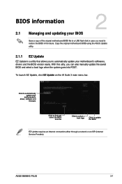
... the BIOS EZ Update requires an Internet connection either through a network or an ISP (Internet Service Provider). Click to automatically update your motherboard's softwares, drivers and the BIOS version easily. ASUS B85M-G PLUS 2-1 With this utlity, you can also manually update the saved BIOS and select a boot logo when the system goes into POST.
... the BIOS EZ Update requires an Internet connection either through a network or an ISP (Internet Service Provider). Click to automatically update your motherboard's softwares, drivers and the BIOS version easily. ASUS B85M-G PLUS 2-1 With this utlity, you can also manually update the saved BIOS and select a boot logo when the system goes into POST.
User Guide
Page 33
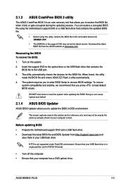
... default BIOS values. Doing so can restore a corrupted BIOS file using the motherboard support DVD or a USB flash drive that contains the updated BIOS file. • Before using this section are for the BIOS file. ASUS B85M-G PLUS 2-3 2.1.3 ASUS CrashFree BIOS 3 utility The ASUS CrashFree BIOS 3 is an auto recovery tool that allows you to update...
... default BIOS values. Doing so can restore a corrupted BIOS file using the motherboard support DVD or a USB flash drive that contains the updated BIOS file. • Before using this section are for the BIOS file. ASUS B85M-G PLUS 2-3 2.1.3 ASUS CrashFree BIOS 3 utility The ASUS CrashFree BIOS 3 is an auto recovery tool that allows you to update...

User Guide
Page 36
.... Select the Load Optimized Defaults item under two modes: EZ Mode and Advanced Mode. Entering BIOS Setup at startup To enter BIOS Setup at www.asus.com to download the latest BIOS file for information on . See section 2.10 Exit Menu for details. • If the system fails to boot ... BIOS Setup after POST To enter BIOS Setup after changing any BIOS setting, load the default settings to ensure system compatibility and stability. Do this motherboard. • Ensure that a USB mouse is connected to your data or system. BIOS menu screen The BIOS setup program can be used under the ...
.... Select the Load Optimized Defaults item under two modes: EZ Mode and Advanced Mode. Entering BIOS Setup at startup To enter BIOS Setup at www.asus.com to download the latest BIOS file for information on . See section 2.10 Exit Menu for details. • If the system fails to boot ... BIOS Setup after POST To enter BIOS Setup after changing any BIOS setting, load the default settings to ensure system compatibility and stability. Do this motherboard. • Ensure that a USB mouse is connected to your data or system. BIOS menu screen The BIOS setup program can be used under the ...

User Guide
Page 37
...motherboard temperature, CPU voltage output, and CPU/chassis fan speed Selects the display language of the BIOS setup program Exits the BIOS setup program without saving the changes, saves the changes and resets the system, or enters the Advanced Mode Selects the Advanced mode functions Normal mode ASUS... to select the display language, system performance mode and boot device priority. The default screen for the advanced BIOS settings. ASUS B85M-G PLUS 2-7 To access the Advanced Mode, click Exit/Advanced Mode, then select Advanced Mode or press F7 for entering the BIOS...
...motherboard temperature, CPU voltage output, and CPU/chassis fan speed Selects the display language of the BIOS setup program Exits the BIOS setup program without saving the changes, saves the changes and resets the system, or enters the Advanced Mode Selects the Advanced mode functions Normal mode ASUS... to select the display language, system performance mode and boot device priority. The default screen for the advanced BIOS settings. ASUS B85M-G PLUS 2-7 To access the Advanced Mode, click Exit/Advanced Mode, then select Advanced Mode or press F7 for entering the BIOS...

User Guide
Page 43
Select the User Password item and press . 2. ASUS B85M-G PLUS 2-13 To change a user password: 1. To clear the user password, follow the same steps as in a new password, then press . 4. Scroll down to create/confirm ... of the screen shows Not Installed. 2.5 Ai Tweaker menu The Ai Tweaker menu items allow you clear the password, the User Password item on the motherboard. From the Create New Password box, key in changing a user password, but press when prompted to display the other items. Target CPU Turbo-Mode Speed...
Select the User Password item and press . 2. ASUS B85M-G PLUS 2-13 To change a user password: 1. To clear the user password, follow the same steps as in a new password, then press . 4. Scroll down to create/confirm ... of the screen shows Not Installed. 2.5 Ai Tweaker menu The Ai Tweaker menu items allow you clear the password, the User Password item on the motherboard. From the Create New Password box, key in changing a user password, but press when prompted to display the other items. Target CPU Turbo-Mode Speed...


