AT3IONT-I Series user's manual
Page 3
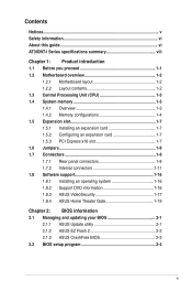
Contents Notices...v Safety information vi About this guide vi AT3IONT-I Series specifications summary viii Chapter 1: Product introduction 1.1 Before you proceed 1-1 1.2 Motherboard overview 1-2 1.2.1 Motherboard layout 1-2 1.2.2 Layout contents 1-2 1.3 Central Processing Unit (CPU ... 1-8 1.7.1 Rear panel connectors 1-8 1.7.2 Internal connectors 1-11 1.8 Software support 1-16 1.8.1 Installing an operating system 1-16 1.8.2 Support DVD information 1-16 1.8.3 ASUS VideoSecurity 1-17 1.8.4 ASUS Home Theater Gate 1-19 Chapter 2: BIOS information 2.1 Managing and updating your BIOS...
Contents Notices...v Safety information vi About this guide vi AT3IONT-I Series specifications summary viii Chapter 1: Product introduction 1.1 Before you proceed 1-1 1.2 Motherboard overview 1-2 1.2.1 Motherboard layout 1-2 1.2.2 Layout contents 1-2 1.3 Central Processing Unit (CPU ... 1-8 1.7.1 Rear panel connectors 1-8 1.7.2 Internal connectors 1-11 1.8 Software support 1-16 1.8.1 Installing an operating system 1-16 1.8.2 Support DVD information 1-16 1.8.3 ASUS VideoSecurity 1-17 1.8.4 ASUS Home Theater Gate 1-19 Chapter 2: BIOS information 2.1 Managing and updating your BIOS...

AT3IONT-I Series user's manual
Page 10
... cause severe damage to page ix for buying an ASUS® AT3IONT-I SERIES Onboard LED 1-1 Chapter 1: Product introduction The illustration below shows the location of accessories. • AT3IONT-I Series motherboards include AT3IONT-I and AT3IONT-I DELUXE two models. Onboard LED The motherboard comes... any of the following precautions before you install motherboard components or change any motherboard component. SB_PWR AT3IONT-I DELUXE ON OFF Standby Power Powered Off AT3IONT-I Series motherboard! Chapter 1 Product introduction Thank you for the list of the onboard LED....
... cause severe damage to page ix for buying an ASUS® AT3IONT-I SERIES Onboard LED 1-1 Chapter 1: Product introduction The illustration below shows the location of accessories. • AT3IONT-I Series motherboards include AT3IONT-I and AT3IONT-I DELUXE two models. Onboard LED The motherboard comes... any of the following precautions before you install motherboard components or change any motherboard component. SB_PWR AT3IONT-I DELUXE ON OFF Standby Power Powered Off AT3IONT-I Series motherboard! Chapter 1 Product introduction Thank you for the list of the onboard LED....

AT3IONT-I Series user's manual
Page 11
... panel audio connector (10-1 pin AAFP) USB connector (10-1 pin USB78, USB910) Page 1-14 1-8 1-1 1-11 1-13 1-12 ASUS AT3IONT-I Series 1-2 Ensure that you install the motherboard into the holes indicated by circles to secure the motherboard to the rear part of the ...chassis. SATA power connectors (4-pin SATA_PWR1) 6. 1.2 1.2.1 Motherboard overview Motherboard layout ASUS AT3IONT-I Series motherboards include AT3IONT-I and AT3IONT-I DELUXE two models The layout varies with external ports goes to the chassis. CPU, power, and chassis fan connectors...
... panel audio connector (10-1 pin AAFP) USB connector (10-1 pin USB78, USB910) Page 1-14 1-8 1-1 1-11 1-13 1-12 ASUS AT3IONT-I Series 1-2 Ensure that you install the motherboard into the holes indicated by circles to secure the motherboard to the rear part of the ...chassis. SATA power connectors (4-pin SATA_PWR1) 6. 1.2 1.2.1 Motherboard overview Motherboard layout ASUS AT3IONT-I Series motherboards include AT3IONT-I and AT3IONT-I DELUXE two models The layout varies with external ports goes to the chassis. CPU, power, and chassis fan connectors...
AT3IONT-I Series user's manual
Page 13
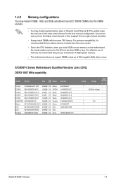
...Hynix 9HF22D9KPT J1108EDSE-DJ-F J5308BASE-AC-E J5308BASE-AC-E J5308BASE-AC-E D1288JEKAPGA7U 9HF22D9KPT N2CB1G80CN-BE H5TQ1G83AFP G7C Timing 7 7 7 - AT3IONT-I Series 1-4 For effective use of 256 megabits (Mb) chips or less. Voltage DIMM support A* B* - •• ...;• - •• 1.5V •• - •• - •• - •• - •• ASUS AT3IONT-I Series Motherboard Qualified Vendors Lists (QVL) DDR3-1067 MHz capability Vendor Part No. 1.4.2 Memory configurations You may install 512MB, 1GB, and 2GB unbuffered...
...Hynix 9HF22D9KPT J1108EDSE-DJ-F J5308BASE-AC-E J5308BASE-AC-E J5308BASE-AC-E D1288JEKAPGA7U 9HF22D9KPT N2CB1G80CN-BE H5TQ1G83AFP G7C Timing 7 7 7 - AT3IONT-I Series 1-4 For effective use of 256 megabits (Mb) chips or less. Voltage DIMM support A* B* - •• ...;• - •• 1.5V •• - •• - •• - •• - •• ASUS AT3IONT-I Series Motherboard Qualified Vendors Lists (QVL) DDR3-1067 MHz capability Vendor Part No. 1.4.2 Memory configurations You may install 512MB, 1GB, and 2GB unbuffered...
AT3IONT-I Series user's manual
Page 15
ASUS AT3IONT-I Series motherboards. SS: Single-sided / DS: Double-sided DIMM support: • A*: Supports one module inserted into either slot as the single-channel memory... 2048MB 2048MB 2048MB Kingtiger PATRIOT PATRIOT PATRIOT KTG2G1333PG3 PSD31G13332H PSD31G13332 PSD32G13332H 2048MB 1024MB 1024MB 2048MB SS/ DS Brand Chip No. Voltage - Visit the ASUS website at 1066MHz on AT3IONT-I Series 1-6 J1108BASE-DJ-E J1108BASE-DJ-E 8FD22D9JNM 8DD22D9JNM SEC 904 HCH9 K4B1G0846D PM64M8D38U-15 - DIMM support A* B - - •• 9 - •• - - ••...
ASUS AT3IONT-I Series motherboards. SS: Single-sided / DS: Double-sided DIMM support: • A*: Supports one module inserted into either slot as the single-channel memory... 2048MB 2048MB 2048MB Kingtiger PATRIOT PATRIOT PATRIOT KTG2G1333PG3 PSD31G13332H PSD31G13332 PSD32G13332H 2048MB 1024MB 1024MB 2048MB SS/ DS Brand Chip No. Voltage - Visit the ASUS website at 1066MHz on AT3IONT-I Series 1-6 J1108BASE-DJ-E J1108BASE-DJ-E 8FD22D9JNM 8DD22D9JNM SEC 904 HCH9 K4B1G0846D PM64M8D38U-15 - DIMM support A* B - - •• 9 - •• - - ••...
AT3IONT-I Series user's manual
Page 17
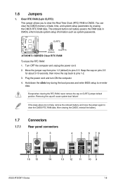
... failure! After clearing the CMOS, reinstall the battery. 1.7 Connectors 1.7.1 Rear panel connectors 1 2 3 4 5 6 78 16 15 14 13 12 11 10 9 ASUS AT3IONT-I SERIES Clear RTC RAM To erase the RTC RAM: 1. You can clear the CMOS memory of date, time, and system setup parameters by erasing the... CMOS RTC RAM data. Turn OFF the computer and unplug the power cord. 2. AT3IONT-I DELUXE 12 23 CLRTC Normal (Default) Clear RTC AT3IONT-I Series 1-8 Except when clearing the RTC RAM, never remove the cap on pins 2-3 for about 5-10 seconds, then...
... failure! After clearing the CMOS, reinstall the battery. 1.7 Connectors 1.7.1 Rear panel connectors 1 2 3 4 5 6 78 16 15 14 13 12 11 10 9 ASUS AT3IONT-I SERIES Clear RTC RAM To erase the RTC RAM: 1. You can clear the CMOS memory of date, time, and system setup parameters by erasing the... CMOS RTC RAM data. Turn OFF the computer and unplug the power cord. 2. AT3IONT-I DELUXE 12 23 CLRTC Normal (Default) Clear RTC AT3IONT-I Series 1-8 Except when clearing the RTC RAM, never remove the cap on pins 2-3 for about 5-10 seconds, then...
AT3IONT-I Series user's manual
Page 19
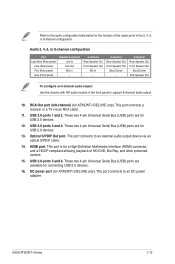
... audio output device via an RCA cable. 11. ASUS AT3IONT-I DELUXE only). These two 4-pin Universal Serial Bus (USB) ports are for connecting USB 2.0 devices. 16. These two 4-pin Universal Serial Bus (USB) ports are for AT3IONT-I Series 1-10 HDMI port. DC power port ...(for a High-Definition Multimedia Interface (HDMI) connector, and is for AT3IONT-I DELUXE only). Optical S/PDIF Out port. USB 2.0 ports 5 and 6. USB 2.0 ports ...
... audio output device via an RCA cable. 11. ASUS AT3IONT-I DELUXE only). These two 4-pin Universal Serial Bus (USB) ports are for connecting USB 2.0 devices. 16. These two 4-pin Universal Serial Bus (USB) ports are for AT3IONT-I Series 1-10 HDMI port. DC power port ...(for a High-Definition Multimedia Interface (HDMI) connector, and is for AT3IONT-I DELUXE only). Optical S/PDIF Out port. USB 2.0 ports 5 and 6. USB 2.0 ports ...
AT3IONT-I Series user's manual
Page 21
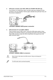
...+ GND USB+5V USB_P10USB_P10+ GND NC PIN 1 USB+5V USB_P7USB_P7+ GND USB+5V USB_P8USB_P8+ GND NC AT3IONT-I DELUXE only) This connector is for USB 2.0 ports. AT3IONT-I DELUXE AT3IONT-I Series 1-12 USB connectors (10-1 pin USB78, USB910) These connectors are for SATA power cable. These... The USB module cable is designed to a slot opening at the back of the system chassis. ASUS AT3IONT-I SERIES SATA power connector 3. SATA power connector (4-pin SATA_PWR1) (for AT3IONT-I SERIES USB2.0 connectors Never connect a 1394 cable to 480 Mbps connection speed. 2. Connect the ...
...+ GND USB+5V USB_P10USB_P10+ GND NC PIN 1 USB+5V USB_P7USB_P7+ GND USB+5V USB_P8USB_P8+ GND NC AT3IONT-I DELUXE only) This connector is for USB 2.0 ports. AT3IONT-I DELUXE AT3IONT-I Series 1-12 USB connectors (10-1 pin USB78, USB910) These connectors are for SATA power cable. These... The USB module cable is designed to a slot opening at the back of the system chassis. ASUS AT3IONT-I SERIES SATA power connector 3. SATA power connector (4-pin SATA_PWR1) (for AT3IONT-I SERIES USB2.0 connectors Never connect a 1394 cable to 480 Mbps connection speed. 2. Connect the ...
AT3IONT-I Series user's manual
Page 23
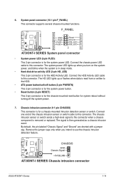
... PWR LED PWR BTN PIN 1 HD_LED RESET GND PWR PLEDPLED+ Reset Ground IDE_LEDIDE_LED+ AT3IONT-I Series 1-14 The system power LED lights up or flashes when data is removed or replaced. By default, the pin labeled "Chassis Signal" ...sensor or switch cable to this connector. The chassis intrusion sensor or switch sends a high-level signal to this connector. AT3IONT-I DELUXE CHASSIS GND Chassis Signal +5VSB_MB AT3IONT-I SERIES Chassis intrusion connector ASUS AT3IONT-I SERIES System panel connector • System power LED (2-pin PLED) This 2-pin connector is for a chassis-mounted ...
... PWR LED PWR BTN PIN 1 HD_LED RESET GND PWR PLEDPLED+ Reset Ground IDE_LEDIDE_LED+ AT3IONT-I Series 1-14 The system power LED lights up or flashes when data is removed or replaced. By default, the pin labeled "Chassis Signal" ...sensor or switch cable to this connector. The chassis intrusion sensor or switch sends a high-level signal to this connector. AT3IONT-I DELUXE CHASSIS GND Chassis Signal +5VSB_MB AT3IONT-I SERIES Chassis intrusion connector ASUS AT3IONT-I SERIES System panel connector • System power LED (2-pin PLED) This 2-pin connector is for a chassis-mounted ...
AT3IONT-I Series user's manual
Page 25
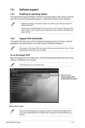
Visit the ASUS website at any time without notice. The following screen is NOT enabled in your OS documentation for detailed information. • Ensure that you install Windows&#... Support DVD Place the Support DVD to install If Autorun is for updates. The contents of the Support DVD to change at www.asus.com for reference only. ASUS AT3IONT-I Series 1-16 Always install the latest OS version and corresponding updates to maximize the features of your computer, browse the contents of the...
Visit the ASUS website at any time without notice. The following screen is NOT enabled in your OS documentation for detailed information. • Ensure that you install Windows&#... Support DVD Place the Support DVD to install If Autorun is for updates. The contents of the Support DVD to change at www.asus.com for reference only. ASUS AT3IONT-I Series 1-16 Always install the latest OS version and corresponding updates to maximize the features of your computer, browse the contents of the...
AT3IONT-I Series user's manual
Page 27
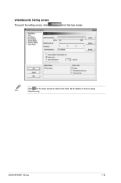
VideoSecurity Setting screen To launch the setting screen, click from the main screen. ASUS AT3IONT-I Series 1-18 Click for the main screen to refer to the Help file for details on how to setup VideoSecurity.
VideoSecurity Setting screen To launch the setting screen, click from the main screen. ASUS AT3IONT-I Series 1-18 Click for the main screen to refer to the Help file for details on how to setup VideoSecurity.

AT3IONT-I Series user's manual
Page 29
...;it�t�h�e��A�S��U�S���w�e�b��s�it�e��a�t http://support.asus.com/download/download. aspx?SLanguage=en-us for the latest supported type. • Due to Window® XP limitation, you have to install the UDF...
...;it�t�h�e��A�S��U�S���w�e�b��s�it�e��a�t http://support.asus.com/download/download. aspx?SLanguage=en-us for the latest supported type. • Due to Window® XP limitation, you have to install the UDF...
AT3IONT-I Series user's manual
Page 31
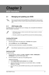
... in the support DVD that you wish to download then click Next. Select Update BIOS from the Internet a. Select the ASUS FTP site nearest you to complete the installation. Chapter 2 BIOS information 2.1 Managing and updating your BIOS Save a copy ... Click the Utilities tab, then click ASUS Update. 3. Place the support DVD in the future. b. From the Windows® desktop, click Start > Programs > ASUS > ASUSUpdate > ASUSUpdate to launch the ASUS Update utility. 2. Installing ASUS Update To install ASUS Update: 1. The Drivers menu appears. 2. ASUS AT3IONT-I Series 2-1
... in the support DVD that you wish to download then click Next. Select Update BIOS from the Internet a. Select the ASUS FTP site nearest you to complete the installation. Chapter 2 BIOS information 2.1 Managing and updating your BIOS Save a copy ... Click the Utilities tab, then click ASUS Update. 3. Place the support DVD in the future. b. From the Windows® desktop, click Start > Programs > ASUS > ASUSUpdate > ASUSUpdate to launch the ASUS Update utility. 2. Installing ASUS Update To install ASUS Update: 1. The Drivers menu appears. 2. ASUS AT3IONT-I Series 2-1

AT3IONT-I Series user's manual
Page 33
...the support DVD may not be the latest version. Ensure to load the BIOS default settings to the floppy disk drive, if supported. 3. ASUS AT3IONT-I Series 2-3 • This function supports USB flash disks with motherboard models. Turn off the system after the utility completes the updating process and...file. 4. Select the Load Setup Defaults item under the Exit menu. Download the latest BIOS file from the ASUS website at www.asus.com. • The removable device that ASUS CrashFree BIOS support vary with FAT 32/16 format and single partition only. • DO NOT shut down ...
...the support DVD may not be the latest version. Ensure to load the BIOS default settings to the floppy disk drive, if supported. 3. ASUS AT3IONT-I Series 2-3 • This function supports USB flash disks with motherboard models. Turn off the system after the utility completes the updating process and...file. 4. Select the Load Setup Defaults item under the Exit menu. Download the latest BIOS file from the ASUS website at www.asus.com. • The removable device that ASUS CrashFree BIOS support vary with FAT 32/16 format and single partition only. • DO NOT shut down ...
AT3IONT-I Series user's manual
Page 35
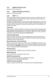
...] [ARMD] LBA/Large Mode [Auto] Enables or disables the LBA mode. Configuration options: [Auto] [0] [1] [2] [3] [4] DMA Mode [Auto] Selects the DMA mode. Configuration options: [Disabled] [Enabled] ASUS AT3IONT-I Series 2-5 The BIOS automatically detects the values opposite the dimmed items (Device, Vendor, Size, LBA Mode, Block Mode, PIO Mode, Async DMA, Ultra DMA, and...
...] [ARMD] LBA/Large Mode [Auto] Enables or disables the LBA mode. Configuration options: [Auto] [0] [1] [2] [3] [4] DMA Mode [Auto] Selects the DMA mode. Configuration options: [Disabled] [Enabled] ASUS AT3IONT-I Series 2-5 The BIOS automatically detects the values opposite the dimmed items (Device, Vendor, Size, LBA Mode, Block Mode, PIO Mode, Async DMA, Ultra DMA, and...

AT3IONT-I Series user's manual
Page 37
... to [Manual]. set the iGPU OverClock Mode item to enable or disable the Intel® Hyper Threading technology. Configuration options: [Auto] [Min.=1.21000V] [Max.=2.47000V] ASUS AT3IONT-I Series 2-7 Configuration options: [Disabled] [Enabled] Hyper Threading Technology [Enabled] Allows you to determine whether to select the system clock mode. iGPU OverClock [450] Allows you...
... to [Manual]. set the iGPU OverClock Mode item to enable or disable the Intel® Hyper Threading technology. Configuration options: [Auto] [Min.=1.21000V] [Max.=2.47000V] ASUS AT3IONT-I Series 2-7 Configuration options: [Disabled] [Enabled] Hyper Threading Technology [Enabled] Allows you to determine whether to select the system clock mode. iGPU OverClock [450] Allows you...
AT3IONT-I Series user's manual
Page 39
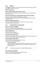
... [Auto] Allows you to disable the iGPU frame buffer detect or set to Enabled. Configuration options: [Disabled] [Enabled] The following two items appear only on AT3IONT-I Series 2-9 Select an item then press to enable or disable the onboard LAN controller. If High Definition Audio Front Panel used, please set the Azalia... [Enabled] Allows you to display. MCP7A Configuration Primary Graphics Adapter [PCIE VGA Card First] Allows you to display the sub-menu. Configuration options: [Enabled] [Disabled] ASUS AT3IONT-I DELUXE motherboard.
... [Auto] Allows you to disable the iGPU frame buffer detect or set to Enabled. Configuration options: [Disabled] [Enabled] The following two items appear only on AT3IONT-I Series 2-9 Select an item then press to enable or disable the onboard LAN controller. If High Definition Audio Front Panel used, please set the Azalia... [Enabled] Allows you to display. MCP7A Configuration Primary Graphics Adapter [PCIE VGA Card First] Allows you to display the sub-menu. Configuration options: [Enabled] [Disabled] ASUS AT3IONT-I DELUXE motherboard.
AT3IONT-I Series user's manual
Page 41
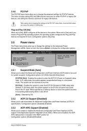
.... When signaled by OS. 2.5.2 ACPI 2.0 Support [Disabled] Allows you to add more tables for Advanced Configuration and Power Interface (ACPI) 2.0 specifications. Configuration options: [Disabled] [Enabled] ASUS AT3IONT-I Series 2-11 Configuration options: [No] [Yes] 2.5 Power menu The Power menu items allow you to change the settings for the Advanced Power Management (APM). Detected...
.... When signaled by OS. 2.5.2 ACPI 2.0 Support [Disabled] Allows you to add more tables for Advanced Configuration and Power Interface (ACPI) 2.0 specifications. Configuration options: [Disabled] [Enabled] ASUS AT3IONT-I Series 2-11 Configuration options: [No] [Yes] 2.5 Power menu The Power menu items allow you to change the settings for the Advanced Power Management (APM). Detected...
AT3IONT-I Series user's manual
Page 43
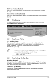
...some power on self tests (POST) while booting to decrease the time needed to change the system boot options. Configuration options: [Disabled] [Enabled] ASUS AT3IONT-I Series 2-13 Configuration options: [Disabled] [Enabled] 2.6 Boot menu The Boot menu items allow you to boot the system. Configuration options: [Removable... Dev.] [Hard Drive] [ATAPI CD-ROM] [Disabled] • To select the boot device during system startup, press when ASUS Logo appears. • To access Windows® OS in the system. Select an item then press to enable or disable the Chassis Q-Fan...
...some power on self tests (POST) while booting to decrease the time needed to change the system boot options. Configuration options: [Disabled] [Enabled] ASUS AT3IONT-I Series 2-13 Configuration options: [Disabled] [Enabled] 2.6 Boot menu The Boot menu items allow you to boot the system. Configuration options: [Removable... Dev.] [Hard Drive] [ATAPI CD-ROM] [Disabled] • To select the boot device during system startup, press when ASUS Logo appears. • To access Windows® OS in the system. Select an item then press to enable or disable the Chassis Q-Fan...
AT3IONT-I Series user's manual
Page 45
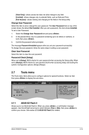
... set to select and update BIOS. Clear User Password Select this item shows Installed. Main Advanced Power BIOS SETUP UTILITY Boot Tools Exit ASUS EZ Flash 2 Express Gate Enter OS Timer Reset User Data AI NET2 [Auto] [10 Seconds] [No] Press ENTER to configure ... message appears. Select the Change User Password item and press . 2. Password Check [Setup] When set or change to any field. [Limited] - ASUS AT3IONT-I Series 2-15 To set your choice. The message Password Installed appears after you to run the utility to [Setup], BIOS checks for details. When set...
... set to select and update BIOS. Clear User Password Select this item shows Installed. Main Advanced Power BIOS SETUP UTILITY Boot Tools Exit ASUS EZ Flash 2 Express Gate Enter OS Timer Reset User Data AI NET2 [Auto] [10 Seconds] [No] Press ENTER to configure ... message appears. Select the Change User Password item and press . 2. Password Check [Setup] When set or change to any field. [Limited] - ASUS AT3IONT-I Series 2-15 To set your choice. The message Password Installed appears after you to run the utility to [Setup], BIOS checks for details. When set...


