AP110 User Manual
Page 3
Contents Disclaimer/Copyrights 2 ASUS Contact Information 6 FCC/CDC Statements 7 Safety Precautions 8 Introduction: About This Manual 9 Audience 10 Contents 10 Conventions 11 References 11 System Package Contents 12 Chapter 1: System ... Panel 20 Remove the Screws 20 Remove the Panel 20 2.2 Remove the Chassis Cover 21 Remove the Screws 21 Remove the Cover 21 2.3 Motherboard Placement 22 Placement Direction 22 Motherboard Screws 22 2.4 Install a CPU 23 CPU Socket Location 23 CPU Orientation 23 Unlock the CPU Socket 24 Insert the CPU 24 Secure...
Contents Disclaimer/Copyrights 2 ASUS Contact Information 6 FCC/CDC Statements 7 Safety Precautions 8 Introduction: About This Manual 9 Audience 10 Contents 10 Conventions 11 References 11 System Package Contents 12 Chapter 1: System ... Panel 20 Remove the Screws 20 Remove the Panel 20 2.2 Remove the Chassis Cover 21 Remove the Screws 21 Remove the Cover 21 2.3 Motherboard Placement 22 Placement Direction 22 Motherboard Screws 22 2.4 Install a CPU 23 CPU Socket Location 23 CPU Orientation 23 Unlock the CPU Socket 24 Insert the CPU 24 Secure...

AP110 User Manual
Page 11
... Refer to the following symbols used throughout this manual. NOTE: Tips and information to complete a task. AP110 Server User's Manual 11 The ASUS websites are not part of the following sources for additional information and for product and software updates. 1.... Information to prevent damage to the components when trying to complete a task. ASUS CUV-2LSV Series Motherboard User's Manual This manual contains detailed information about the CUV-2LV motherboard. 2. ASUS Websites The ASUS websites worldwide provide updated information on page 6. 3. NOTE: These documents are ...
... Refer to the following symbols used throughout this manual. NOTE: Tips and information to complete a task. AP110 Server User's Manual 11 The ASUS websites are not part of the following sources for additional information and for product and software updates. 1.... Information to prevent damage to the components when trying to complete a task. ASUS CUV-2LSV Series Motherboard User's Manual This manual contains detailed information about the CUV-2LV motherboard. 2. ASUS Websites The ASUS websites worldwide provide updated information on page 6. 3. NOTE: These documents are ...
AP110 User Manual
Page 12
System Package Contents The following checklist enumerates the components included in the standard system package. 1) ASUS AS-15 Chassis 2) ASUS CUV-2LV Motherboard 3) 250W ATX Power Supply 4) 50X CD-ROM Drive 5) 1.44MB Floppy Disk Drive 6) Support CD with Drivers and Utilities 7) User's Manuals (for system and motherboard) 8) ASUS System Management Agent (ASMA) Support CD If any of the above items is missing, contact your dealer. 12 Introduction: About This Manual
System Package Contents The following checklist enumerates the components included in the standard system package. 1) ASUS AS-15 Chassis 2) ASUS CUV-2LV Motherboard 3) 250W ATX Power Supply 4) 50X CD-ROM Drive 5) 1.44MB Floppy Disk Drive 6) Support CD with Drivers and Utilities 7) User's Manuals (for system and motherboard) 8) ASUS System Management Agent (ASMA) Support CD If any of the above items is missing, contact your dealer. 12 Introduction: About This Manual
AP110 User Manual
Page 14
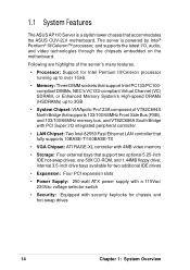
...133/100/66MHz memory bus, and VT82C686A South Bridge with PCI Super I /O, audio, and video technologies through the chipsets embedded on the motherboard. The server is a stylish tower chassis that support two optional 5.25-inch IDE hot-swap drives, one 50X CD-ROM, and 1....composed of the server's many features. • Processor: Support for chassis and hot-swap drives 14 Chapter 1: System Overview 1.1 System Features The ASUS AP110 Server is powered by Intel® Pentium® III/Celeron™ processor, and supports the latest I /O integrated peripheral controller • LAN ...
...133/100/66MHz memory bus, and VT82C686A South Bridge with PCI Super I /O, audio, and video technologies through the chipsets embedded on the motherboard. The server is a stylish tower chassis that support two optional 5.25-inch IDE hot-swap drives, one 50X CD-ROM, and 1....composed of the server's many features. • Processor: Support for chassis and hot-swap drives 14 Chapter 1: System Overview 1.1 System Features The ASUS AP110 Server is powered by Intel® Pentium® III/Celeron™ processor, and supports the latest I /O integrated peripheral controller • LAN ...
AP110 User Manual
Page 17
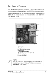
... with all models. If your server includes a RAID kit, it comes already pre-installed in the chassis. 1.4 Internal Features The standard components inside the AP110 server include the motherboard, power supply, floppy and CD-ROM drives, and cables. Hot-swap Drive Trays (optional) 4. CD-ROM Drive 5. 3.5-inch Internal Device Bays 6. The picture...
... with all models. If your server includes a RAID kit, it comes already pre-installed in the chassis. 1.4 Internal Features The standard components inside the AP110 server include the motherboard, power supply, floppy and CD-ROM drives, and cables. Hot-swap Drive Trays (optional) 4. CD-ROM Drive 5. 3.5-inch Internal Device Bays 6. The picture...
AP110 User Manual
Page 22
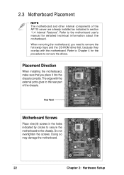
...trays and the CD-ROM drive first, because they overlap with the external ports goes to the motherboard user's manual for the procedure to the chassis. Refer to the rear part of the AP110 server are already installed as indicated in the holes indicated by circles to secure the... motherboard to remove the drives. When removing the motherboard, you place it into the chassis correctly. Doing so may damage the motherboard. 22 Chapter 2: Hardware Setup
...trays and the CD-ROM drive first, because they overlap with the external ports goes to the motherboard user's manual for the procedure to the chassis. Refer to the rear part of the AP110 server are already installed as indicated in the holes indicated by circles to secure the... motherboard to remove the drives. When removing the motherboard, you place it into the chassis correctly. Doing so may damage the motherboard. 22 Chapter 2: Hardware Setup
AP110 User Manual
Page 23
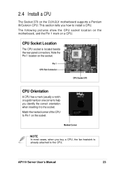
The following pictures show the CPU socket location on the motherboard, and the Pin 1 mark on the socket. Match the marked corner of the CPU to the socket. Pin 1 CPU Fan Connector CPU Socket 370 CPU .... This section tells you buy a CPU, the fan heatsink is located beside the rear panel connectors. 2.4 Install a CPU The Socket 370 on the CUV-2LV motherboard supports a Pentium III/Celeron CPU. AP110 Server User's Manual 23
The following pictures show the CPU socket location on the motherboard, and the Pin 1 mark on the socket. Match the marked corner of the CPU to the socket. Pin 1 CPU Fan Connector CPU Socket 370 CPU .... This section tells you buy a CPU, the fan heatsink is located beside the rear panel connectors. 2.4 Install a CPU The Socket 370 on the CUV-2LV motherboard supports a Pentium III/Celeron CPU. AP110 Server User's Manual 23

AP110 User Manual
Page 25
The lever clicks in place indicating that the socket is for more information. Connect the Fan Cable Connect the CPU fan cable to the socket. Fan Cable CPU_FAN Connector AP110 Server User's Manual 25 NOTE The fan heatsink picture above is locked. 2.4 Install a CPU Secure the CPU Push down the lever to secure the CPU to the 3-pin CPU_FAN connector on the motherboard. The fan heatsink that comes with the CPU for reference only. Refer to the documentation that you purchased may not look exactly the same as shown.
The lever clicks in place indicating that the socket is for more information. Connect the Fan Cable Connect the CPU fan cable to the socket. Fan Cable CPU_FAN Connector AP110 Server User's Manual 25 NOTE The fan heatsink picture above is locked. 2.4 Install a CPU Secure the CPU Push down the lever to secure the CPU to the 3-pin CPU_FAN connector on the motherboard. The fan heatsink that comes with the CPU for reference only. Refer to the documentation that you purchased may not look exactly the same as shown.
AP110 User Manual
Page 26
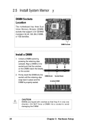
... into the socket until the retaining clips snap back in 32, 64, 128, 256, 512MB, or 1GB densities. 2.5 Install System Memor y DIMM Sockets Location The motherboard has three Dual Inline Memory Module (DIMM) sockets that they fit in only one direction. DIMM Notch Socket Break Installed DIMM CAUTION DIMMs are keyed...
... into the socket until the retaining clips snap back in 32, 64, 128, 256, 512MB, or 1GB densities. 2.5 Install System Memor y DIMM Sockets Location The motherboard has three Dual Inline Memory Module (DIMM) sockets that they fit in only one direction. DIMM Notch Socket Break Installed DIMM CAUTION DIMMs are keyed...

AP110 User Manual
Page 29
... the IDE connector at the back of the drive, matching the red stripe on the cable with Pin 1 on the motherboard. 2.6 Install a Hard Disk Drive Connect the Cables 1. IDE Cable 3. AP110 Server User's Manual 29 Connect one end of the IDE cable to the power connector at the back of the drive...
... the IDE connector at the back of the drive, matching the red stripe on the cable with Pin 1 on the motherboard. 2.6 Install a Hard Disk Drive Connect the Cables 1. IDE Cable 3. AP110 Server User's Manual 29 Connect one end of the IDE cable to the power connector at the back of the drive...

AP110 User Manual
Page 41
... remove the CD-ROM drive for the purpose of removing the motherboard, you can access the motherboard. 4.5 CD-ROM Drive The server comes with the motherboard. Carefully pull the drive out of the Motherboard Hot-swap HHD Trays and CD-ROM Drive Pulled Out AP110 Server User's Manual 41 The CD-ROM drive overlaps with...-install the CD-ROM drive. Power and IDE Cables CD-ROM Screws NOTE If you are doing the above procedure for either one of the motherboard, so you do not have to completely remove the drive from the drive. 2. This section tells how to the chassis. 3.
... remove the CD-ROM drive for the purpose of removing the motherboard, you can access the motherboard. 4.5 CD-ROM Drive The server comes with the motherboard. Carefully pull the drive out of the Motherboard Hot-swap HHD Trays and CD-ROM Drive Pulled Out AP110 Server User's Manual 41 The CD-ROM drive overlaps with...-install the CD-ROM drive. Power and IDE Cables CD-ROM Screws NOTE If you are doing the above procedure for either one of the motherboard, so you do not have to completely remove the drive from the drive. 2. This section tells how to the chassis. 3.

AP110 User Manual
Page 44
The picture below shows the specific device assignments for the plugs. Internal HDD P4. Internal HDD P5. CD-ROM Drive P3. Hot-swap HDD P6. Floppy Disk Drive 44 Appendix A: Power Supply P2 P4 P3 P1 P5 P6 P7 P1. Motherboard ATX Power P2. The power supply has an internal cooling fan. The power supply has seven plugs labeled P1 to P7. A.1 General Description The server comes with a 250W ATX power supply with universal AC input that includes PFC and ATX-compliant output cables and connectors. Hot-swap HDD P7.
The picture below shows the specific device assignments for the plugs. Internal HDD P4. Internal HDD P5. CD-ROM Drive P3. Hot-swap HDD P6. Floppy Disk Drive 44 Appendix A: Power Supply P2 P4 P3 P1 P5 P6 P7 P1. Motherboard ATX Power P2. The power supply has an internal cooling fan. The power supply has seven plugs labeled P1 to P7. A.1 General Description The server comes with a 250W ATX power supply with universal AC input that includes PFC and ATX-compliant output cables and connectors. Hot-swap HDD P7.
AP110 User Manual
Page 49
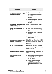
... detect HDDs Press F6 and load the PCI-IDE RAID driver when booting from the motherboard support CD. Make sure the network cable is connector the RJ-45 port on The message "...Non-system disk or disk error" appears 1. AP110 Server User's Manual 49 Run FDISK utility to solve the problem. RAID HDD shows incorrect ...unstable Network connection not available Install the VIA utility drivers from DOS/Win9x floppy disk. 2. Boot from the ASUS support CD. 1. Reboot the system and run FDISK /MBR. Make sure that you installed the DIMMs ...
... detect HDDs Press F6 and load the PCI-IDE RAID driver when booting from the motherboard support CD. Make sure the network cable is connector the RJ-45 port on The message "...Non-system disk or disk error" appears 1. AP110 Server User's Manual 49 Run FDISK utility to solve the problem. RAID HDD shows incorrect ...unstable Network connection not available Install the VIA utility drivers from DOS/Win9x floppy disk. 2. Boot from the ASUS support CD. 1. Reboot the system and run FDISK /MBR. Make sure that you installed the DIMMs ...

