
A8V-XE User Manual for English Edition
Page 1
A8V-XE Motherboard
A8V-XE Motherboard

A8V-XE User Manual for English Edition
Page 3
... contents Notices vi Safety information vii Operation Safety vii About this guide viii A8V-XE specifications summary x Chapter 1: Hardware information 1.1 Welcome 1-2 1.2 Package contents 1-2 1.3 Special features 1-3 1.3.1 Product highlights 1-3 1.3.2 Innovative ASUS features 1-4 1.4 Before you proceed 1-5 1.5 Motherboard Overview 1-6 1.5.1 Placement direction 1-6 1.5.2 Screw holes 1-6 1.5.3 Motherboard layout 1-7 1.6 Central Processing Unit (CPU 1-8 1.6.1 Overview 1-8 1.6.2 Installing the CPU 1-8 1.6.3 Installing the CPU heatsink...
... contents Notices vi Safety information vii Operation Safety vii About this guide viii A8V-XE specifications summary x Chapter 1: Hardware information 1.1 Welcome 1-2 1.2 Package contents 1-2 1.3 Special features 1-3 1.3.1 Product highlights 1-3 1.3.2 Innovative ASUS features 1-4 1.4 Before you proceed 1-5 1.5 Motherboard Overview 1-6 1.5.1 Placement direction 1-6 1.5.2 Screw holes 1-6 1.5.3 Motherboard layout 1-7 1.6 Central Processing Unit (CPU 1-8 1.6.1 Overview 1-8 1.6.2 Installing the CPU 1-8 1.6.3 Installing the CPU heatsink...

A8V-XE User Manual for English Edition
Page 7
Operation safety • Before installing the motherboard and adding devices on it may become wet. • Place the product on a stable surface. • If you are connected. Do not place the product ... the power cables are not sure about the voltage of electronic products. If you add a device. • Before connecting or removing signal cables from the motherboard, ensure that all power cables from the existing system before you detect any area where it , carefully read all the manuals that your retailer. vii...
Operation safety • Before installing the motherboard and adding devices on it may become wet. • Place the product on a stable surface. • If you are connected. Do not place the product ... the power cables are not sure about the voltage of electronic products. If you add a device. • Before connecting or removing signal cables from the motherboard, ensure that all power cables from the existing system before you detect any area where it , carefully read all the manuals that your retailer. vii...

A8V-XE User Manual for English Edition
Page 8
...8226; Chapter 1: Product introduction This chapter describes the features of the jumpers and connectors on ASUS hardware and software products. It includes description of the motherboard and the new technology it supports. How this guide This user guide contains the information ... viii Refer to change system settings through the BIOS Setup menus. ASUS websites The ASUS website provides updated information on the motherboard. • Chapter 2: BIOS setup This chapter tells how to the ASUS contact information. 2. Optional documentation Your product package may include optional ...
...8226; Chapter 1: Product introduction This chapter describes the features of the jumpers and connectors on ASUS hardware and software products. It includes description of the motherboard and the new technology it supports. How this guide This user guide contains the information ... viii Refer to change system settings through the BIOS Setup menus. ASUS websites The ASUS website provides updated information on the motherboard. • Chapter 2: BIOS setup This chapter tells how to the ASUS contact information. 2. Optional documentation Your product package may include optional ...

A8V-XE User Manual for English Edition
Page 13
This chapter describes the motherboard features and the new technologies it supports. 1Product introduction
This chapter describes the motherboard features and the new technologies it supports. 1Product introduction
A8V-XE User Manual for English Edition
Page 14
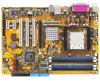
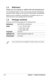
Before you for the following items. Motherboard ASUS A8V-XE motherboard Cables Accessories 1 x 2 in your package with the list below. 1.2 Package contents Check your retailer. 1-2 Chapter 1: Product introduction Thank you start installing the motherboard, and hardware devices on it another standout in the long line of new features and latest technologies, making it , check the items in...
Before you for the following items. Motherboard ASUS A8V-XE motherboard Cables Accessories 1 x 2 in your package with the list below. 1.2 Package contents Check your retailer. 1-2 Chapter 1: Product introduction Thank you start installing the motherboard, and hardware devices on it another standout in the long line of new features and latest technologies, making it , check the items in...

A8V-XE User Manual for English Edition
Page 15
... for details. See pages 1-21 and 1-22 for details. AMD Cool ʻnʼ Quiet!™ Technology The motherboard supports the AMD Cool ʻnʼ Quiet!™ Technology that dynamically and automatically changes the CPU speed, voltage and ..., performance, investment protection, and reduced total cost of inappropriate connection. Serial ATA 3Gb/s technology The motherboard supports the Serial ATA 3 Gb/s technology through the Serial ATA interfaces. ASUS A8V-XE 1-3 ADI SoundMAX High-Definition audio The onboard 6-channel AD1986A High Definition audio CODEC enables...
... for details. See pages 1-21 and 1-22 for details. AMD Cool ʻnʼ Quiet!™ Technology The motherboard supports the AMD Cool ʻnʼ Quiet!™ Technology that dynamically and automatically changes the CPU speed, voltage and ..., performance, investment protection, and reduced total cost of inappropriate connection. Serial ATA 3Gb/s technology The motherboard supports the Serial ATA 3 Gb/s technology through the Serial ATA interfaces. ASUS A8V-XE 1-3 ADI SoundMAX High-Definition audio The onboard 6-channel AD1986A High Definition audio CODEC enables...

A8V-XE User Manual for English Edition
Page 16
...2-6 for details. feature of the motherboard BIOS allows automatic re-setting to the BIOS default settings in the motherboard allows you can easily update the system BIOS even before loading the operating system. ASUS EZ Flash BIOS With the ASUS EZ Flash, you to personalize and...out on USB 2.0. PCI Express™ interface The motherboard fully supports PCI Express, the latest I /O Port This motherboard provides convenient connectivity to external home theater audio systems via an S/PDIF-out (SONY-PHILIPS Digital Interface) jack. ASUS MyLogo™ This new feature present in case the...
...2-6 for details. feature of the motherboard BIOS allows automatic re-setting to the BIOS default settings in the motherboard allows you can easily update the system BIOS even before loading the operating system. ASUS EZ Flash BIOS With the ASUS EZ Flash, you to personalize and...out on USB 2.0. PCI Express™ interface The motherboard fully supports PCI Express, the latest I /O Port This motherboard provides convenient connectivity to external home theater audio systems via an S/PDIF-out (SONY-PHILIPS Digital Interface) jack. ASUS MyLogo™ This new feature present in case the...

A8V-XE User Manual for English Edition
Page 17
Failure to do so may cause severe damage to indicate that came with a green standby power LED. Onboard LED The motherboard comes with the component. • Before you install or remove any component, ensure that the ATX power supply is switched off... a grounded antistatic pad or in softoff mode, and not powered OFF. This LED lights up to the motherboard, peripherals, and/or components. A8V-XE R A8V-XE Onboard LED SB_PWR ON Standby Power OFF Powered Off ASUS A8V-XE 1-5 1.4 Before you proceed Take note of the following precautions before you install components into the system. &#...
Failure to do so may cause severe damage to indicate that came with a green standby power LED. Onboard LED The motherboard comes with the component. • Before you install or remove any component, ensure that the ATX power supply is switched off... a grounded antistatic pad or in softoff mode, and not powered OFF. This LED lights up to the motherboard, peripherals, and/or components. A8V-XE R A8V-XE Onboard LED SB_PWR ON Standby Power OFF Powered Off ASUS A8V-XE 1-5 1.4 Before you proceed Take note of the following precautions before you install components into the system. &#...

A8V-XE User Manual for English Edition
Page 18
... configuration of your chassis to unplug the power cord before installing or removing the motherboard. Failure to do so can damage the motherboard. Place this side towards the rear of the chassis as indicated in the correct orientation. ... physical injury and damage motherboard components. 1.5.1 Placement direction When installing the motherboard, make sure that the motherboard fits into the holes indicated by circles to secure the motherboard to the rear part of the chassis A8V-XE R 1-6 Chapter 1: Product introduction 1.5 Motherboard overview Before you place ...
... configuration of your chassis to unplug the power cord before installing or removing the motherboard. Failure to do so can damage the motherboard. Place this side towards the rear of the chassis as indicated in the correct orientation. ... physical injury and damage motherboard components. 1.5.1 Placement direction When installing the motherboard, make sure that the motherboard fits into the holes indicated by circles to secure the motherboard to the rear part of the chassis A8V-XE R 1-6 Chapter 1: Product introduction 1.5 Motherboard overview Before you place ...

A8V-XE User Manual for English Edition
Page 20
...A8V-XE R A8V-XE CPU Socket 939 Before installing the CPU, make sure that the socket box is facing towards you and the load lever is on the socket to ensure correct installation. Take note of these processors can run applications faster than processors with gold triangle) on the motherboard...64257;c corner on your left. 1-8 Chapter 1: Product introduction Locate the CPU socket on the CPU. 1.6 Central Processing Unit (CPU) 1.6.1 Overview The motherboard comes with a surface mount 939-pin Zero Insertion Force (ZIF) socket designed for the AMD Athlon™ 64FX, AMD Athlon 64™ ,AMD ...
...A8V-XE R A8V-XE CPU Socket 939 Before installing the CPU, make sure that the socket box is facing towards you and the load lever is on the socket to ensure correct installation. Take note of these processors can run applications faster than processors with gold triangle) on the motherboard...64257;c corner on your left. 1-8 Chapter 1: Product introduction Locate the CPU socket on the CPU. 1.6 Central Processing Unit (CPU) 1.6.1 Overview The motherboard comes with a surface mount 939-pin Zero Insertion Force (ZIF) socket designed for the AMD Athlon™ 64FX, AMD Athlon 64™ ,AMD ...

A8V-XE User Manual for English Edition
Page 22
... the CPU heatsink or CPU before you purchased a separate CPU heatsink and fan assembly, make sure that a Thermal Interface Material is already installed on the motherboard upon purchase. • You do not match the CPU documentation, follow the latter. 1-10 Chapter 1: Product introduction 1.6.3 Installing the heatsink and fan The AMD Athlon... the retention module base. • The retention module base is properly applied to remove the retention module base when installing the CPU or installing other motherboard components. • If you install the heatsink and fan assembly.
... the CPU heatsink or CPU before you purchased a separate CPU heatsink and fan assembly, make sure that a Thermal Interface Material is already installed on the motherboard upon purchase. • You do not match the CPU documentation, follow the latter. 1-10 Chapter 1: Product introduction 1.6.3 Installing the heatsink and fan The AMD Athlon... the retention module base. • The retention module base is properly applied to remove the retention module base when installing the CPU or installing other motherboard components. • If you install the heatsink and fan assembly.

A8V-XE User Manual for English Edition
Page 23
... end of the retention bracket to the retention module base. 1 2 3 4 5 3. Make sure that the retention bracket is in place. CPU_FAN Rotation +12V GND A8V-XE R A8V-XE CPU Fan Connector ASUS A8V-XE Do not forget to the retention module base. Hardware monitoring errors can occur if you cannot snap the retention bracket in place. 4. A clicking sound... one end of the retention bracket (near the retention bracket lock) to connect the CPU fan connector! Push down the retention bracket lock on the motherboard labeled CPU_FAN.
... end of the retention bracket to the retention module base. 1 2 3 4 5 3. Make sure that the retention bracket is in place. CPU_FAN Rotation +12V GND A8V-XE R A8V-XE CPU Fan Connector ASUS A8V-XE Do not forget to the retention module base. Hardware monitoring errors can occur if you cannot snap the retention bracket in place. 4. A clicking sound... one end of the retention bracket (near the retention bracket lock) to connect the CPU fan connector! Push down the retention bracket lock on the motherboard labeled CPU_FAN.

A8V-XE User Manual for English Edition
Page 24
... (DDR) Dual Inline Memory Module (DIMM) sockets. The following figure illustrates the location of the sockets: 104 Pins DIMM_A1 DIMM_A2 DIMM_B1 DIMM_B2 80 Pins A8V-XE R A8V-XE 184-pin DDR DIMM Sockets Channel Channel A Channel B Sockets DIMM_A1 and DIMM_A2 DIMM_B1 and DIMM_B2 1.7.2 Memory configurations You may install 64MB, 128 MB, 256 MB... recommend that you installed four 1 GB DDR memory modules, the system may detect not more than 3GB of address space allocation. 1.7 System memory 1.7.1 Overview The motherboard comes with the same CAS latency.
... (DDR) Dual Inline Memory Module (DIMM) sockets. The following figure illustrates the location of the sockets: 104 Pins DIMM_A1 DIMM_A2 DIMM_B1 DIMM_B2 80 Pins A8V-XE R A8V-XE 184-pin DDR DIMM Sockets Channel Channel A Channel B Sockets DIMM_A1 and DIMM_A2 DIMM_B1 and DIMM_B2 1.7.2 Memory configurations You may install 64MB, 128 MB, 256 MB... recommend that you installed four 1 GB DDR memory modules, the system may detect not more than 3GB of address space allocation. 1.7 System memory 1.7.1 Overview The motherboard comes with the same CAS latency.
A8V-XE User Manual for English Edition
Page 27
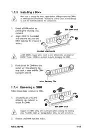
... the retaining clips outward. 2. Simultaneously press the retaining clips outward to remove a DIMM. 2 1. ASUS A8V-XE 1-15 1.7.3 Installing a DIMM Make sure to unplug the power supply before adding or removing DIMMs or other system components. Remove the DIMM from the socket. Firmly insert the DIMM into a socket to both the motherboard and the components. 1.
... the retaining clips outward. 2. Simultaneously press the retaining clips outward to remove a DIMM. 2 1. ASUS A8V-XE 1-15 1.7.3 Installing a DIMM Make sure to unplug the power supply before adding or removing DIMMs or other system components. Remove the DIMM from the socket. Firmly insert the DIMM into a socket to both the motherboard and the components. 1.
A8V-XE User Manual for English Edition
Page 28
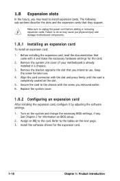
...with the slot and press firmly until the card is already installed in a chassis). 3. Remove the system unit cover (if your motherboard is completely seated on BIOS setup. 2. Align the card connector with the screw you removed earlier. 6. Remove the bracket opposite the slot ... came with it by adjusting the software settings. 1. 1.8 Expansion slots In the future, you may cause you physical injury and damage motherboard components. 1.8.1 Installing an expansion card To install an expansion card: 1. The following sub-sections describe the slots and the expansion cards that ...
...with the slot and press firmly until the card is already installed in a chassis). 3. Remove the system unit cover (if your motherboard is completely seated on BIOS setup. 2. Align the card connector with the screw you removed earlier. 6. Remove the bracket opposite the slot ... came with it by adjusting the software settings. 1. 1.8 Expansion slots In the future, you may cause you physical injury and damage motherboard components. 1.8.1 Installing an expansion card To install an expansion card: 1. The following sub-sections describe the slots and the expansion cards that ...
A8V-XE User Manual for English Edition
Page 29
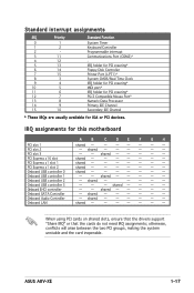
...shared - - - - - - - shared - - - - - - - shared - - - - - - IRQ assignments for ISA or PCI devices. shared - - - - - - ASUS A8V-XE 1-17 shared - - - - - - - - shared - - - - - - - When using PCI cards on shared slots, ensure that the drivers support "Share IRQ" or that the ...PCI steering* PS/2 Compatible Mouse Port* Numeric Data Processor Primary IDE Channel Secondary IDE Channel * These IRQs are usually available for this motherboard PCI slot 1 PCI slot 2 PCI slot 3 PCI Express x16 slot PCI Express x1 slot 1 PCI Express x1 slot 2 Onboard USB...
...shared - - - - - - - shared - - - - - - - shared - - - - - - IRQ assignments for ISA or PCI devices. shared - - - - - - ASUS A8V-XE 1-17 shared - - - - - - - - shared - - - - - - - When using PCI cards on shared slots, ensure that the drivers support "Share IRQ" or that the ...PCI steering* PS/2 Compatible Mouse Port* Numeric Data Processor Primary IDE Channel Secondary IDE Channel * These IRQs are usually available for this motherboard PCI slot 1 PCI slot 2 PCI slot 3 PCI Express x16 slot PCI Express x1 slot 1 PCI Express x1 slot 2 Onboard USB...

A8V-XE User Manual for English Edition
Page 30
... Before using a PCI VGA card, make sure to set the Graphics Adapter Priority to PCI/Int-VGA in the BIOS. 1.8.5 PCI Express x16 slot This motherboard supports PCI Express x16 graphic cards that comply with the PCI Express specifications. 1.8.3 PCI Express x1 slot This...
... Before using a PCI VGA card, make sure to set the Graphics Adapter Priority to PCI/Int-VGA in the BIOS. 1.8.5 PCI Express x16 slot This motherboard supports PCI Express x16 graphic cards that comply with the PCI Express specifications. 1.8.3 PCI Express x1 slot This...

A8V-XE User Manual for English Edition
Page 35
PRI_IDE SEC_IDE A8V-XE R A8V-XE IDE Connectors ASUS A8V-XE 1-23 IDE connectors (40-1 pin PRI_IDE, SEC_IDE) These connectors are for the jumper settings. • Pin 20 on the IDE connector is removed to match ... for an Ultra DMA 133/100/66/33 IDE master device (hard disk drive). PIN1 PIN1 NOTE: Orient the red markings (usually zigzag) on the motherboard, a black connector for an Ultra DMA 133/100/66/33 IDE slave device (optical drive/hard disk drive), and a gray connector for Ultra DMA 133...
PRI_IDE SEC_IDE A8V-XE R A8V-XE IDE Connectors ASUS A8V-XE 1-23 IDE connectors (40-1 pin PRI_IDE, SEC_IDE) These connectors are for the jumper settings. • Pin 20 on the IDE connector is removed to match ... for an Ultra DMA 133/100/66/33 IDE master device (hard disk drive). PIN1 PIN1 NOTE: Orient the red markings (usually zigzag) on the motherboard, a black connector for an Ultra DMA 133/100/66/33 IDE slave device (optical drive/hard disk drive), and a gray connector for Ultra DMA 133...

A8V-XE User Manual for English Edition
Page 37
Insufficient air flow inside the system may damage the motherboard components. CPU_FAN A8V-XE R CHA_FAN A8V-XE Fan Connectors Rotation +12V GND Rotation +12V GND ASUS A8V-XE 1-25 Connect the fan cables to the fan connectors. These are not jumpers! Do not forget to connect the fan cables to the fan connectors ...) The fan connectors support cooling fans of 350 mA~740 mA (8.88 W max.) or a total of the connector. Do not place jumper caps on the motherboard, making sure that the black wire of each cable matches the ground pin of 1 A~2.22 A (26.64 W max.) at +12V.
Insufficient air flow inside the system may damage the motherboard components. CPU_FAN A8V-XE R CHA_FAN A8V-XE Fan Connectors Rotation +12V GND Rotation +12V GND ASUS A8V-XE 1-25 Connect the fan cables to the fan connectors. These are not jumpers! Do not forget to connect the fan cables to the fan connectors ...) The fan connectors support cooling fans of 350 mA~740 mA (8.88 W max.) or a total of the connector. Do not place jumper caps on the motherboard, making sure that the black wire of each cable matches the ground pin of 1 A~2.22 A (26.64 W max.) at +12V.


