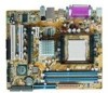
A8V-VM User's Manual for English Edition
Page 3
Table of contents Notices vi Safety information vii A8V-VM specifications summary viii Chapter 1: Product introduction 1.1 Welcome 1-2 1.2 Package contents 1-2 1.3 Special features 1-3 1.3.1 Product highlights 1-3 1.3.2 Innovative ASUS features 1-4 1.4 Before you proceed 1-5 1.5 Motherboard overview 1-6 1.5.1 Motherboard layout 1-6 1.5.2 Placement direction 1-6 1.5.3 Screw holes 1-7 1.6 Central Processing Unit (CPU 1-8 1.6.1 Overview 1-8 1.6.2 Installing the CPU 1-8 1.6.3 Installing the heatsink and fan 1-10 1.7 System memory 1-12 1.7.1 Overview 1-12...
A8V-VM User's Manual for English Edition
Page 7
...staples away from connectors, slots, sockets and circuitry. • Avoid dust, humidity, and temperature extremes. Operation safety • Before installing the motherboard and adding devices on a stable surface. • If you are not damaged. Do not place the product in any damage, contact your ..., make sure all power cables are connected. If you add a device. • Before connecting or removing signal cables from the motherboard, ensure that all cables are correctly connected and the power cables are using an adapter or extension cord. vii If possible, disconnect all...
A8V-VM User's Manual for English Edition
Page 8
...for product and software updates. 1. It also lists the hardware setup procedures that you need when installing and configuring the motherboard. Refer to the following parts: • Chapter 1: Product introduction This chapter describes the features of the standard package.... Refer to the ASUS contact information. 2. These documents are also provided. • Chapter 3: Software support This chapter describes the contents of the jumpers and connectors on ASUS hardware and software products. ASUS websites The ASUS website provides updated information on the motherboard. • Chapter...
A8V-VM User's Manual for English Edition
Page 13
This chapter describes the motherboard features and the new technologies it supports. 1Product introduction
A8V-VM User's Manual for English Edition
Page 14
Before you for the following items. Motherboard ASUS A8V-VM motherboard Cables Accessories 1 x floppy disk drive cable 1 x Ultral DMA 133/100/66 cable 1 x SATA power cable 1 x SATA signal cable I/O shield Application CDs ASUS motherboard support CD Documentation User guide If any of ASUS quality motherboards! 1.1 Welcome! The motherboard delivers a host of new features and latest technologies, making it , check the items...
A8V-VM User's Manual for English Edition
Page 15
...;g��e�1��-�8��f�o�r�d��e�t�a�il�s�. ASUS A8V-VM 1- 1.3 Special features 1.3.1 Product highlights AMD Dual-Core Architecture The motherboard supports AMD dual-core processors containing two physical CPU cores with Yamaha DLSbyXG sound set, 5.1 Virtual TheaterTM and ...state-of the industry's first x86-64 technology. Dual-channel DDR400 memory support Employing the Double Date Rate (DDR) memory technology, the motherboard supports up to meet demands for details.
A8V-VM User's Manual for English Edition
Page 16
.... AMD Cool 'n' Quiet!™ Technology The motherboard supports the AMD Cool 'n' Quiet!™ Technology that dynamically and automatically changes the CPU speed, voltage and amount of power depending on the task the CPU performs. 1.3.2 Innovative ASUS features CrashFree BIOS 2 This feature allows you to... of the current Serial ATA products with lower pin count, reduced voltage requirement. See page 2-6 for details. ASUS MyLogo™ This new feature present in the motherboard allows you can easily update the system BIOS even before loading the operating system. The Serial ATA 3 Gb/s...
A8V-VM User's Manual for English Edition
Page 17
A8V-VM R A8V-VM Onboard LED SB_PWR ON Standby Power OFF Powered Off ASUS A8V-VM 1- Onboard LED The motherboard comes with the component. • Before you install or remove any system component. Unplug the power cable from the power supply. This LED lights up ...; Use a grounded wrist strap or touch a safely grounded object or a metal object, such as the power supply case, before installing any component, ensure that the ATX power supply is switched off or the power cord is detached from the power outlet and make sure that the standby power LED is ON...
A8V-VM User's Manual for English Edition
Page 18
... you physical injury and damage motherboard components. 1.5.1 Placement direction When installing the motherboard, make sure that the motherboard fits into the holes indicated by circles to secure the motherboard to unplug the power cord before installing or removing the motherboard. The edge with external ports... to the chassis. Do not overtighten the screws! Failure to do so can damage the motherboard. Place this side towards the rear of your chassis to ensure that you install the motherboard, study the configuration of the chassis A8V-VM R 1- Chapter 1: Product introduction
A8V-VM User's Manual for English Edition
Page 20
... a CPU: 1. Locate the CPU socket on your left. 1- Chapter 1: Product introduction Gold Arrow A8V-VM R A8V-VM CPU Socket 939 Before installing the CPU, make sure that the socket box is facing towards you and the load lever is on the motherboard. The 128-bit-wide data paths of the marked corner (with gold triangle...
A8V-VM User's Manual for English Edition
Page 22
Place the heatsink on top of the installed CPU, making sure that a Thermal Interface Material is already installed on the motherboard upon purchase. • You do not match the CPU documentation, follow the latter. 1-10 Chapter 1: Product introduction If the instructions ...module base. • The retention module base is properly applied to remove the retention module base when installing the CPU or installing other motherboard components. • If you install the heatsink and fan assembly. CPU Fan CPU Heatsink Retention bracket Retention Module Base Retention bracket lock Your...
A8V-VM User's Manual for English Edition
Page 23
...the retention mechanism to secure the heatsink and fan to the retention module base. Push down the retention bracket lock on the motherboard labeled CPU_FAN. Align the other end of the retention bracket to connect the CPU fan connector! Make sure that the retention ... plug this connector. 1-11 Hardware monitoring errors can occur if you cannot snap the retention bracket in place. 4. CPU_FAN GND +12V Rotation A8V-VM R A8V-VM CPU Fan Connector ASUS A8V-VM Do not forget to the retention module base. 1 2 3 4 5 3. Attach one end of the retention bracket (near the retention bracket...
A8V-VM User's Manual for English Edition
Page 24
... you install four 1 GB memory modules, the system may detect less than 3 GB of the total memory because of the sockets: DIMM_A1 DIMM_A2 DIMM_B1 DIMM_B2 A8V-VM R A8V-VM 184-pin DDR DIMM Sockets Dual-channel mode Pair 1 Pair 2 Sockets DIMM_A1 and DIMM_B1 DIMM_A2 and DIMM_B2 1.7.2 Memory configurations You may install 128 MB, 256... and DIMM_B1 slots. • Always install DIMMs with four 184-pin Double Data Rate (DDR) Dual Inline Memory Module (DIMM) sockets. 1.7 System memory 1.7.1 Overview The motherboard comes with the same CAS latency.
A8V-VM User's Manual for English Edition
Page 27
... motherboard and the components. 1. The DIMM might get damaged when it fits in place and the DIMM is keyed with a notch so that it flips out with your fingers when pressing the retaining clips. Remove the DIMM from the socket. Simultaneously press the retaining clips outward to avoid damaging the DIMM. 3. ASUS A8V-VM...
A8V-VM User's Manual for English Edition
Page 28
...bracket opposite the slot that you intend to unplug the power cord before adding or removing expansion cards. Remove the system unit cover (if your motherboard is completely seated on the next page. 3. Make sure to use . 4. Keep the screw for the expansion card. 1-16 Chapter 1:... do so may need to the tables on the slot. 5. 1.8 Expansion slots In the future, you may cause you physical injury and damage motherboard components. 1.8.1 Installing an expansion card To install an expansion card: 1. Secure the card to the card. Replace the system cover. 1.8.2 Configuring an...
A8V-VM User's Manual for English Edition
Page 29
... Processor Primary IDE Channel Secondary IDE Channel * These IRQs are usually available for this motherboard A B C D E F G H PCI slot 1 shared - - - - - - - Onboard USB controller 1 - - Onboard SATA Controller - Onboard Audio Controller - When using PCI cards on shared slots, ensure that the drivers support "Share IRQ" or that the cards do not need IRQ assignments; ASUS A8V-VM 1-17
A8V-VM User's Manual for English Edition
Page 30
... PCI Express x16 graphic cards that comply with the PCI Express specifications. 1.8.3 PCI Express x1 slot This motherboard supports PCI Express x1 network cards, SCSI cards and other cards that comply with the PCI Express specifications. The figure shows a LAN card installed on ...
A8V-VM User's Manual for English Edition
Page 37
... fan connectors on the fan connectors! GND +12V Rotation CPU_FAN GND +12V Rotation A8V-VM R A8V-VM Fan Connectors CHA_FAN ASUS A8V-VM 1-25 4. Insufficient air flow inside the system may damage the motherboard components. Connect the fan cables to the fan connectors. Do not place jumper caps... on the motherboard, making sure that the black wire of each cable matches the ground pin of 1 A~2.22 ...