
User Guide
Page 5
Chapter 3: NVIDIA® SLI™ technology support 3 . 1 Overview 3 - 2 3.1.1 Requirements 3 - 2 3.1.2 ASUS Certified SLI Graphics cards 3 - 2 3 . 2 Dual graphics card setup 3 - 4 3.2.1 Setting the ASUS EZ selector card 3 - 4 3.2.2 Installing SLI-ready graphics cards 3 - 6 3.2.3 Installing the device drivers 3 - 1 0 3.2.4 Enabling the multi-GPU feature in Windows 3 - 1 0 v
Chapter 3: NVIDIA® SLI™ technology support 3 . 1 Overview 3 - 2 3.1.1 Requirements 3 - 2 3.1.2 ASUS Certified SLI Graphics cards 3 - 2 3 . 2 Dual graphics card setup 3 - 4 3.2.1 Setting the ASUS EZ selector card 3 - 4 3.2.2 Installing SLI-ready graphics cards 3 - 6 3.2.3 Installing the device drivers 3 - 1 0 3.2.4 Enabling the multi-GPU feature in Windows 3 - 1 0 v

User Guide
Page 8
... up to 2 GB system memory 2 x PCI Express™ x16 slot for discrete graphics cards* 2 x PCI Express™ x1 slots 3 x PCI slots NVIDIA® nForce™4 SLI chipset supports: - 4 x Ultra DMA 133/100/66/33 hard disk drives - 4 x Serial ATA drives with RAID 0, RAID 1, and RAID 0+1 configurations Realtek® ALC850 8-channel CODEC 1 x Coaxial S/PDIF out port 1 x Optical S/PDIF out port Marvell® 88E81111 PCI Express™ Gigabit LAN controller T1 1394a controller supports: - 2 x IEEE 1394a ports Supports up to 10 USB 2.0 ports 4 Mb Flash ROM, Phoenix-Award BIOS, LPC, Green, PnP...
... up to 2 GB system memory 2 x PCI Express™ x16 slot for discrete graphics cards* 2 x PCI Express™ x1 slots 3 x PCI slots NVIDIA® nForce™4 SLI chipset supports: - 4 x Ultra DMA 133/100/66/33 hard disk drives - 4 x Serial ATA drives with RAID 0, RAID 1, and RAID 0+1 configurations Realtek® ALC850 8-channel CODEC 1 x Coaxial S/PDIF out port 1 x Optical S/PDIF out port Marvell® 88E81111 PCI Express™ Gigabit LAN controller T1 1394a controller supports: - 2 x IEEE 1394a ports Supports up to 10 USB 2.0 ports 4 Mb Flash ROM, Phoenix-Award BIOS, LPC, Green, PnP...
User Guide
Page 21
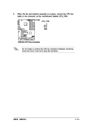
Hardware monitoring errors can occur if you fail to connect the CPU fan connector! CPU_FAN A8N-SLI ® A8N-SLI CPU fan connector Do not forget to plug this connector. When the fan and heatsink assembly is in place, connect the CPU fan cable to the connector on the motherboard labeled CPU_FAN. ASUS A8N-SLI 1-11 GND +12V Rotation 5 .
Hardware monitoring errors can occur if you fail to connect the CPU fan connector! CPU_FAN A8N-SLI ® A8N-SLI CPU fan connector Do not forget to plug this connector. When the fan and heatsink assembly is in place, connect the CPU fan cable to the connector on the motherboard labeled CPU_FAN. ASUS A8N-SLI 1-11 GND +12V Rotation 5 .
User Guide
Page 24
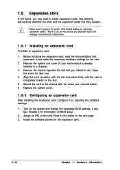
... and change the necessary BIOS settings, if any. Keep the screw for the card. 2 . Make sure to the card. Before installing the expansion card, read the documentation that you removed earlier. 6 . Remove the bracket opposite the slot that came with it by adjusting the software settings. 1 . Replace the system cover. 1 . 5 . 2 Configuring an expansion card After installing the expansion card, configure it and make the necessary hardware settings for later use . Turn...
... and change the necessary BIOS settings, if any. Keep the screw for the card. 2 . Make sure to the card. Before installing the expansion card, read the documentation that you removed earlier. 6 . Remove the bracket opposite the slot that came with it by adjusting the software settings. 1 . Replace the system cover. 1 . 5 . 2 Configuring an expansion card After installing the expansion card, configure it and make the necessary hardware settings for later use . Turn...

User Guide
Page 26
...PCI Express x1 slot This motherboard supports PCI Express x1 network cards, SCSI cards and other cards that comply with the PCI Express specifications. 1 . 5 . 3 PCI slots The PCI slots support cards such as a LAN card, SCSI card, USB card, and other cards that comply with the PCI Express specifications. Single card mode (default) supports: - 1 x PCI Express™ x16 graphics card on a PCI slot. 1 . 5 . 4 PCI Express x16 slot This motherboard supports PCI Express x16 graphic cards that comply with PCI specifications. This motherboard supports the Scalable Link Interface™ (SLI...
...PCI Express x1 slot This motherboard supports PCI Express x1 network cards, SCSI cards and other cards that comply with the PCI Express specifications. 1 . 5 . 3 PCI slots The PCI slots support cards such as a LAN card, SCSI card, USB card, and other cards that comply with the PCI Express specifications. Single card mode (default) supports: - 1 x PCI Express™ x16 graphics card on a PCI slot. 1 . 5 . 4 PCI Express x16 slot This motherboard supports PCI Express x16 graphic cards that comply with PCI specifications. This motherboard supports the Scalable Link Interface™ (SLI...
User Guide
Page 27
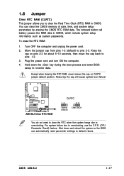
... power cord. 2 . Plug the power cord and turn ON the computer. 4 . Shut down the key during the boot process and enter BIOS setup to re-enter data. You can automatically reset parameter settings to default values. Move the jumper cap from pins 1-2 (default) to pins 1-2. 3 . Keep the cap on CLRTC jumper default position. Removing the cap will cause system boot failure! 1.6 Jumper Clear RTC RAM (CLRTC) This jumper allows you to clear the Real Time Clock (RTC) RAM in CMOS...
... power cord. 2 . Plug the power cord and turn ON the computer. 4 . Shut down the key during the boot process and enter BIOS setup to re-enter data. You can automatically reset parameter settings to default values. Move the jumper cap from pins 1-2 (default) to pins 1-2. 3 . Keep the cap on CLRTC jumper default position. Removing the cap will cause system boot failure! 1.6 Jumper Clear RTC RAM (CLRTC) This jumper allows you to clear the Real Time Clock (RTC) RAM in CMOS...

User Guide
Page 31
... IDE master device (hard disk drive). Refer to PIN 1. This prevents incorrect insertion when you must configure the second drive as a slave device by setting its jumper accordingly. If you install two hard disk drives, you connect the IDE cable. • Use the 80-conductor IDE cable for Ultra DMA 133/100/66 signal cables. SEC_IDE PRI_IDE A8N-SLI ® A8N-SLI IDE connectors PIN 1 NOTE: Orient the red markings (usually zigzag) on the Ultra DMA cable connector. ASUS A8N-SLI 1-21 IDE connectors...
... IDE master device (hard disk drive). Refer to PIN 1. This prevents incorrect insertion when you must configure the second drive as a slave device by setting its jumper accordingly. If you install two hard disk drives, you connect the IDE cable. • Use the 80-conductor IDE cable for Ultra DMA 133/100/66 signal cables. SEC_IDE PRI_IDE A8N-SLI ® A8N-SLI IDE connectors PIN 1 NOTE: Orient the red markings (usually zigzag) on the Ultra DMA cable connector. ASUS A8N-SLI 1-21 IDE connectors...

User Guide
Page 32
... cables for details. In SATA mode, you can connect Serial ATA boot or data hard disk drives to SATA by the NVIDIA® nForce™4 SLI chipset, these connectors, enable the RAID function of each port from the NVRAID Configuration sub-menu item in the BIOS. Serial ATA Master/Slave connectors Connector Color Setting SATA1, SATA2 Black Master SATA3, SATA4 Black Slave Use Boot Disk Data Disk 1-22 Chapter 1: Hardware information If you intend to create a Serial ATA RAID set using these connectors are set...
... cables for details. In SATA mode, you can connect Serial ATA boot or data hard disk drives to SATA by the NVIDIA® nForce™4 SLI chipset, these connectors, enable the RAID function of each port from the NVRAID Configuration sub-menu item in the BIOS. Serial ATA Master/Slave connectors Connector Color Setting SATA1, SATA2 Black Master SATA3, SATA4 Black Slave Use Boot Disk Data Disk 1-22 Chapter 1: Hardware information If you intend to create a Serial ATA RAID set using these connectors are set...

User Guide
Page 35
...; Use of a PSU with more power-consuming devices. See the table below for ATX power supply plugs. Find the proper orientation and push down firmly until the connectors completely fit. • Do not forget to fit these connectors in only one orientation. The power supply plugs are for details. Power supply requirements Components/Peripherals AMD® K8 939-pin CPU type PCIe™ x16 graphics cards DDR DIMMs HDD Optical drive (DVD/CD-RW) PCIe™ x 1 card PCI cards...
...; Use of a PSU with more power-consuming devices. See the table below for ATX power supply plugs. Find the proper orientation and push down firmly until the connectors completely fit. • Do not forget to fit these connectors in only one orientation. The power supply plugs are for details. Power supply requirements Components/Peripherals AMD® K8 939-pin CPU type PCIe™ x16 graphics cards DDR DIMMs HDD Optical drive (DVD/CD-RW) PCIe™ x 1 card PCI cards...

User Guide
Page 38
... the chassis-mounted reset button for system reboot without turning off button (2-pin PWRSW) This connector is for the system power LED. Connect the HDD Activity LED cable to the HDD. • Power/Soft-off the system power. 1-28 Chapter 1: Hardware information Pressing the power button turns the system ON or puts the system in sleep mode. • Hard disk drive activity (2-pin IDE_LED) This 2-pin connector is for the system power button. 1 2 . Ground Reset NC ® IDE_LED RESET * Requires an ATX power supply...
... the chassis-mounted reset button for system reboot without turning off button (2-pin PWRSW) This connector is for the system power LED. Connect the HDD Activity LED cable to the HDD. • Power/Soft-off the system power. 1-28 Chapter 1: Hardware information Pressing the power button turns the system ON or puts the system in sleep mode. • Hard disk drive activity (2-pin IDE_LED) This 2-pin connector is for the system power button. 1 2 . Ground Reset NC ® IDE_LED RESET * Requires an ATX power supply...

User Guide
Page 41
... the updated BIOS file in Flash Memory Writer utility or using the bootable floppy disk you created earlier. 2 . Boot the system in DOS mode using a bootable floppy disk with the latest BIOS file. 3 . d. Press , then follow screen instructions to the optical drive. Copy the original or the latest motherboard BIOS file to the bootable floppy disk. 2 . 1 . 2 AwardBIOS Flash Utility The Basic Input/Output System (BIOS) can be updated using the built-in the floppy disk to avoid loading a wrong BIOS file. Updating the BIOS file 1 . Insert a formatted, high...
... the updated BIOS file in Flash Memory Writer utility or using the bootable floppy disk you created earlier. 2 . Boot the system in DOS mode using a bootable floppy disk with the latest BIOS file. 3 . d. Press , then follow screen instructions to the optical drive. Copy the original or the latest motherboard BIOS file to the bootable floppy disk. 2 . 1 . 2 AwardBIOS Flash Utility The Basic Input/Output System (BIOS) can be updated using the built-in the floppy disk to avoid loading a wrong BIOS file. Updating the BIOS file 1 . Insert a formatted, high...

User Guide
Page 47
... current menu or to its Setup Defaults Saves changes and exits Setup ASUS A8N-SLI 2-9 To access the menu bar items, press the right or left or right Moves the highlight up a selection menu for the highlighted field Scrolls forward through the various setup menus. POWER Use this menu to configure the default system device used to configure and enable Power Management features. BOOT Use this menu to locate and load the Operating System. The keys in...
... current menu or to its Setup Defaults Saves changes and exits Setup ASUS A8N-SLI 2-9 To access the menu bar items, press the right or left or right Moves the highlight up a selection menu for the highlighted field Scrolls forward through the various setup menus. POWER Use this menu to configure the default system device used to configure and enable Power Management features. BOOT Use this menu to locate and load the Operating System. The keys in...

User Guide
Page 50
... manually enter the IDE hard disk drive parameters. Select [Manual] to configure a hard disk drive, make sure you set the IDE Primary Master/Slave to automatically detect an IDE hard disk drive. If automatic detection is installed in the correct values for this sub-menu. 2 . 3 . 5 Primary and Secondary IDE Master/Slave Primary IDE Master x Auto Acoustic Management Disabled Primary IDE Master [Auto] Access Mode [Auto] Select Menu Item Specific Help Press [Enter] to recognize the installed hard disk. 2-12 Chapter 2: BIOS setup These values are not user-configurable...
... manually enter the IDE hard disk drive parameters. Select [Manual] to configure a hard disk drive, make sure you set the IDE Primary Master/Slave to automatically detect an IDE hard disk drive. If automatic detection is installed in the correct values for this sub-menu. 2 . 3 . 5 Primary and Secondary IDE Master/Slave Primary IDE Master x Auto Acoustic Management Disabled Primary IDE Master [Auto] Access Mode [Auto] Select Menu Item Specific Help Press [Enter] to recognize the installed hard disk. 2-12 Chapter 2: BIOS setup These values are not user-configurable...
User Guide
Page 56
... the chipset configuration settings. DRAM Configuration Timing Mode [Auto] x Memclock index value (Mhz) x CAS# Latency (Tcl) 2.5 x Min RAS# active time (Tras) x RAS# to CAS# delay (Trcd) x Row precharge time (Trp) 2T x 1/T/2T Memory Timing 2T Bottom of 32-bit [31:24] IO DRAM Over 4G Remapping [Disabled] MTRR mapping mode [Continuous] 200Mhz 8T 4T [E0] Select Menu Item Specific Help to select DRAM configuration. [Auto] is recommended. [Manual...
... the chipset configuration settings. DRAM Configuration Timing Mode [Auto] x Memclock index value (Mhz) x CAS# Latency (Tcl) 2.5 x Min RAS# active time (Tras) x RAS# to CAS# delay (Trcd) x Row precharge time (Trp) 2T x 1/T/2T Memory Timing 2T Bottom of 32-bit [31:24] IO DRAM Over 4G Remapping [Disabled] MTRR mapping mode [Continuous] 200Mhz 8T 4T [E0] Select Menu Item Specific Help to select DRAM configuration. [Auto] is recommended. [Manual...
User Guide
Page 59
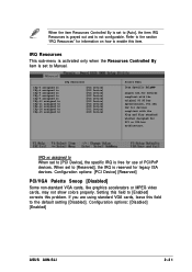
... [Enabled] corrects this field to the default setting [Disabled]. Refer to the section "IRQ Resources" for PCI or ISA bus architecture. Configuration options: [Disabled] [Enabled] ASUS A8N-SLI 2-21 Configuration options: [PCI Device] [Reserved] PCI/VGA Palette Snoop [Disabled] Some non-standard VGA cards, like graphics accelerators or MPEG video cards, may not show colors properly. When the item Resources Controlled By is set to [Auto], the item IRQ Resources is grayed out and is reserved for legacy...
... [Enabled] corrects this field to the default setting [Disabled]. Refer to the section "IRQ Resources" for PCI or ISA bus architecture. Configuration options: [Disabled] [Enabled] ASUS A8N-SLI 2-21 Configuration options: [PCI Device] [Reserved] PCI/VGA Palette Snoop [Disabled] Some non-standard VGA cards, like graphics accelerators or MPEG video cards, may not show colors properly. When the item Resources Controlled By is set to [Auto], the item IRQ Resources is grayed out and is reserved for legacy...

User Guide
Page 60
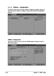
Select an item then press to display a pop-up menu with the configuration options. Onboard Device Configuration IDE Function Setup NVRAID Configuration USB Configuration Onboard LAN Onboard LAN Boot ROM AC97 Audio [Enabled] [Disabled] [Enabled] PCI IEEE 1394a Serial Port 1 Address Parallel Port Address Parallel Port Mode ECP Mode Use DMA [Enabled] [3F8/IRQ4] [378/IRQ7] [ECP+EPP] 3 Select Menu Item Specific Help 2-22 Chapter 2: BIOS setup 2 . 4 . 4 Onboard device configuration The items in this menu show the onboard device configuration settings.
Select an item then press to display a pop-up menu with the configuration options. Onboard Device Configuration IDE Function Setup NVRAID Configuration USB Configuration Onboard LAN Onboard LAN Boot ROM AC97 Audio [Enabled] [Disabled] [Enabled] PCI IEEE 1394a Serial Port 1 Address Parallel Port Address Parallel Port Mode ECP Mode Use DMA [Enabled] [3F8/IRQ4] [378/IRQ7] [ECP+EPP] 3 Select Menu Item Specific Help 2-22 Chapter 2: BIOS setup 2 . 4 . 4 Onboard device configuration The items in this menu show the onboard device configuration settings.

User Guide
Page 64
... you to enable or disable the onboard AC`97 Audio controller. Configuration options: [SPP] [EPP] [ECP] [ECP+EPP] ECP Mode Use DMA [3] Allows you wish to use the onboard LAN feature. Configuration options: [1] [3] 2-26 Chapter 2: BIOS setup Keep the default [Enabled] if you to select the ECP Mode. Configuration options: [Disabled] [Enabled] Serial Port1 Address [3F8/IRQ4] Allows you to enable or disable the onboard IEEE 1394a device support. Configuration options: [Disabled] [Enabled] PCI IEEE 1394a [Enabled] Allows you to set the addresses for the onboard serial port connector. This...
... you to enable or disable the onboard AC`97 Audio controller. Configuration options: [SPP] [EPP] [ECP] [ECP+EPP] ECP Mode Use DMA [3] Allows you wish to use the onboard LAN feature. Configuration options: [1] [3] 2-26 Chapter 2: BIOS setup Keep the default [Enabled] if you to select the ECP Mode. Configuration options: [Disabled] [Enabled] Serial Port1 Address [3F8/IRQ4] Allows you to enable or disable the onboard IEEE 1394a device support. Configuration options: [Disabled] [Enabled] PCI IEEE 1394a [Enabled] Allows you to set the addresses for the onboard serial port connector. This...

User Guide
Page 67
.... Configuration options: [Disabled] [Enabled] ASUS A8N-SLI 2-29 Restore on AC Power Loss [Enabled] PWR Button < 4 secs [Instant-Off] WOL (PME#) From Soft-Off [Enabled] WOR (RI#) From Soft-Off [Enabled] Power-On by Alarm [Disabled] x Date (of Month) 0 x Time (hh:mm:ss) Alarm 0 : 0 : 0 Power Up By PS2 Keyboard [Disabled] Power Up By PS2 Mouse [Disabled] Select Menu Item Specific Help Press [Enter] to select whether or not to display a pop-up menu with...
.... Configuration options: [Disabled] [Enabled] ASUS A8N-SLI 2-29 Restore on AC Power Loss [Enabled] PWR Button < 4 secs [Instant-Off] WOL (PME#) From Soft-Off [Enabled] WOR (RI#) From Soft-Off [Enabled] Power-On by Alarm [Disabled] x Date (of Month) 0 x Time (hh:mm:ss) Alarm 0 : 0 : 0 Power Up By PS2 Keyboard [Disabled] Power Up By PS2 Mouse [Disabled] Select Menu Item Specific Help Press [Enter] to select whether or not to display a pop-up menu with...

User Guide
Page 78
... PowerPack! See "8. 3.1 Overview The motherboard supports the NVIDIA® SLI™ (Scalable Link Interface) technology that allows you to ensure optimum peformance. ATX power connectors" on page 2-25 for details. • The NVIDIA SLI technology supports Windows® XP™ operating system only. • Visit the NVIDIA website for the supported 3D applications and the latest graphics card drivers. 3 . 1 . 2 ASUS Certified SLI Graphics cards Use only ASUS certified PCI Express x16 SLI graphics cards to install two identical PCI Express™ x16 graphics cards.
... PowerPack! See "8. 3.1 Overview The motherboard supports the NVIDIA® SLI™ (Scalable Link Interface) technology that allows you to ensure optimum peformance. ATX power connectors" on page 2-25 for details. • The NVIDIA SLI technology supports Windows® XP™ operating system only. • Visit the NVIDIA website for the supported 3D applications and the latest graphics card drivers. 3 . 1 . 2 ASUS Certified SLI Graphics cards Use only ASUS certified PCI Express x16 SLI graphics cards to install two identical PCI Express™ x16 graphics cards.
User Guide
Page 86
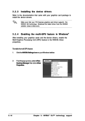
... graphics cards and the device drivers, enable the Multi-Graphics Processing Unit (GPU) feature in Windows® After installing your PCI Express graphics card driver supports the NVIDIA SLI technology. 3 . 2 . 3 Installing the device drivers Refer to install the device drivers. From the pop-up menu, select nView Desktop Manager then click nView Properties. 3-10 Chapter 3: NVIDIA® SLI™ technology support Make sure that came with your Windows taskbar. 2. To enable the multi-GPU feature: 1. Download the latest driver from the NVIDIA website (www.nvidia...
... graphics cards and the device drivers, enable the Multi-Graphics Processing Unit (GPU) feature in Windows® After installing your PCI Express graphics card driver supports the NVIDIA SLI technology. 3 . 2 . 3 Installing the device drivers Refer to install the device drivers. From the pop-up menu, select nView Desktop Manager then click nView Properties. 3-10 Chapter 3: NVIDIA® SLI™ technology support Make sure that came with your Windows taskbar. 2. To enable the multi-GPU feature: 1. Download the latest driver from the NVIDIA website (www.nvidia...


