
User Manual
Page 6
...; Technology 5-41 5.7.1 Enabling Cool 'n' Quiet!™ Technology 5-41 5.7.2 Launching the Cool 'n' Quiet!™ software 5-42 Chapter 6: SLI™ technology support 6.1 Overview 6-1 6.2 Dual graphics card setup 6-2 6.2.1 Setting the ASUS EZ selector card 6-2 6.2.2 Installing SLI-ready graphics cards 6-4 6.2.3 Setting the SLI mode in BIOS 6-8 6.2.4 Installing the device drivers 6-8 6.2.5 Enabling the multi-GPU feature in Windows 6-8 Appendix A.1 Using the SATA extension module A-1 A.1.1 Installing the 2-port SATA extension module ......... A-1 A.1.1 Installing SATA hard drives...
...; Technology 5-41 5.7.1 Enabling Cool 'n' Quiet!™ Technology 5-41 5.7.2 Launching the Cool 'n' Quiet!™ software 5-42 Chapter 6: SLI™ technology support 6.1 Overview 6-1 6.2 Dual graphics card setup 6-2 6.2.1 Setting the ASUS EZ selector card 6-2 6.2.2 Installing SLI-ready graphics cards 6-4 6.2.3 Setting the SLI mode in BIOS 6-8 6.2.4 Installing the device drivers 6-8 6.2.5 Enabling the multi-GPU feature in Windows 6-8 Appendix A.1 Using the SATA extension module A-1 A.1.1 Installing the 2-port SATA extension module ......... A-1 A.1.1 Installing SATA hard drives...

User Manual
Page 9
... this guide is organized This manual contains the following parts: • Chapter 1: Product introduction This chapter describes the features of the motherboard and the new technology it supports. • Chapter 2: Hardware information This chapter lists the hardware setup procedures that comes with the motherboard package. • Chapter 6: NVIDIA® SLI™ technology support This chapter tells how to install SLI-ready PCI Express graphics cards. • Appendix: Installation options This...
... this guide is organized This manual contains the following parts: • Chapter 1: Product introduction This chapter describes the features of the motherboard and the new technology it supports. • Chapter 2: Hardware information This chapter lists the hardware setup procedures that comes with the motherboard package. • Chapter 6: NVIDIA® SLI™ technology support This chapter tells how to install SLI-ready PCI Express graphics cards. • Appendix: Installation options This...

User Manual
Page 19
... of system memory using IDE or Serial ATA devices. Dual RAID solution Onboard RAID controllers provide the motherboard with dual-RAID functionality that speeds up the PCI bus. ASUS A8N-SLI Deluxe 1-3 See pages 2-21, 2-22 and 5-18 for four SATA and two PATA connectors. PCI Express features point-to-point serial interconnections between integrated circuits in packets. The NVIDIA® nForce4® SLI™ allows RAID 0, RAID 1, RAID 1+0 and JBOD configuration for details. This high speed interface is a high-speed, low latency...
... of system memory using IDE or Serial ATA devices. Dual RAID solution Onboard RAID controllers provide the motherboard with dual-RAID functionality that speeds up the PCI bus. ASUS A8N-SLI Deluxe 1-3 See pages 2-21, 2-22 and 5-18 for four SATA and two PATA connectors. PCI Express features point-to-point serial interconnections between integrated circuits in packets. The NVIDIA® nForce4® SLI™ allows RAID 0, RAID 1, RAID 1+0 and JBOD configuration for details. This high speed interface is a high-speed, low latency...

User Manual
Page 22
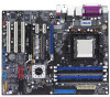
... the overall system temperature. ASUS Q-Fan technology The ASUS Q-Fan technology smartly adjusts the fan speeds according to the system loading to buy a replacement ROM chip. CrashFree BIOS 2 This feature allows you of the system boot status and causes of boot errors, if any. ASUS Two-slot thermal design The motherboard is designed with two PCI Express x1 slots placed between the PCI Express x16 slots allowing an increase in airflow between SLI mode (Dual Video Cards) and Normal mode (Single card). This promotes...
... the overall system temperature. ASUS Q-Fan technology The ASUS Q-Fan technology smartly adjusts the fan speeds according to the system loading to buy a replacement ROM chip. CrashFree BIOS 2 This feature allows you of the system boot status and causes of boot errors, if any. ASUS Two-slot thermal design The motherboard is designed with two PCI Express x1 slots placed between the PCI Express x16 slots allowing an increase in airflow between SLI mode (Dual Video Cards) and Normal mode (Single card). This promotes...

User Manual
Page 40
... the screw for the card. 2. Turn on BIOS setup. 2. Align the card connector with the screw you intend to the chassis with the slot and press firmly until the card is already installed in a chassis). 3. Assign an IRQ to the tables on the slot. 5. Install the software drivers for information on the system and change the necessary BIOS settings, if any. Refer to the card. See Chapter 4 for the...
... the screw for the card. 2. Turn on BIOS setup. 2. Align the card connector with the screw you intend to the chassis with the slot and press firmly until the card is already installed in a chassis). 3. Assign an IRQ to the tables on the slot. 5. Install the software drivers for information on the system and change the necessary BIOS settings, if any. Refer to the card. See Chapter 4 for the...
User Manual
Page 61
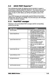
... boot status. 3.3 ASUS POST Reporter™ This motherboard includes the Winbond speech controller to one of the PCI slots, or a PCI Express AGP card into the PCI Express x16 slot. • Make sure that your graphics card is not defective. • Check your CPU overclocking settings in the BIOS setup and restore the default CPU parameters. • Check if your keyboard is a list of the problem. In case of a boot failure, you will hear the specific cause of the default POST...
... boot status. 3.3 ASUS POST Reporter™ This motherboard includes the Winbond speech controller to one of the PCI slots, or a PCI Express AGP card into the PCI Express x16 slot. • Make sure that your graphics card is not defective. • Check your CPU overclocking settings in the BIOS setup and restore the default CPU parameters. • Check if your keyboard is a list of the problem. In case of a boot failure, you will hear the specific cause of the default POST...

User Manual
Page 70
... be updated using the AwardBIOS Flash Utility. Follow these instructions to a floppy disk. Download the latest BIOS file from the Software folder of the support CD to continue. 2. From the Open field, type D:\bootdisk\makeboot a: assuming that D: is your optical drive. Boot the system in the floppy disk to A 8 N - When the A : > appears, replace the bootable floppy disk with the latest BIOS file. 3. c. d. The Award AwardBIOS Flash Utility for ASUS V1.01 (C) Phoenix Technologies Ltd. All Rights Reserved BIOS Flash Utility screen...
... be updated using the AwardBIOS Flash Utility. Follow these instructions to a floppy disk. Download the latest BIOS file from the Software folder of the support CD to continue. 2. From the Open field, type D:\bootdisk\makeboot a: assuming that D: is your optical drive. Boot the system in the floppy disk to A 8 N - When the A : > appears, replace the bootable floppy disk with the latest BIOS file. 3. c. d. The Award AwardBIOS Flash Utility for ASUS V1.01 (C) Phoenix Technologies Ltd. All Rights Reserved BIOS Flash Utility screen...
User Manual
Page 75
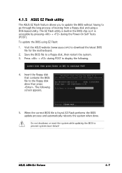
... BIOS file is accessible by pressing + during POST to continue POST 4. Press + during the Power-On Self Tests (POST). To update the BIOS using a DOS-based utility. 4.1.5 ASUS EZ Flash utility The ASUS EZ Flash feature allows you to update the BIOS without having to go through the long process of booting from a floppy disk and using EZ Flash: 1. Insert Disk then press Enter or ESC to display the following screen appears. The EZ Flash utility is built-in the BIOS chip...
... BIOS file is accessible by pressing + during POST to continue POST 4. Press + during the Power-On Self Tests (POST). To update the BIOS using a DOS-based utility. 4.1.5 ASUS EZ Flash utility The ASUS EZ Flash feature allows you to update the BIOS without having to go through the long process of booting from a floppy disk and using EZ Flash: 1. Insert Disk then press Enter or ESC to display the following screen appears. The EZ Flash utility is built-in the BIOS chip...

User Manual
Page 76
... motherboard package. Place the support CD in Windows® environment. The D r i v e r s menu appears. 2. X X . See page 5-3 for the U t i l i t i e s screen menu. 3. Quit all Windows® applications before you to your system. Click the U t i l i t i e s tab, then click I n s t a l l A S U S U p d a t e V X . ASUS Update requires an Internet connection either through a network or an Internet Service Provider (ISP). X X. Installing ASUS Update To install ASUS Update: 1. The ASUS Update utility allows you update the BIOS using this utility. 4-8 Chapter 4: BIOS setup...
... motherboard package. Place the support CD in Windows® environment. The D r i v e r s menu appears. 2. X X . See page 5-3 for the U t i l i t i e s screen menu. 3. Quit all Windows® applications before you to your system. Click the U t i l i t i e s tab, then click I n s t a l l A S U S U p d a t e V X . ASUS Update requires an Internet connection either through a network or an Internet Service Provider (ISP). X X. Installing ASUS Update To install ASUS Update: 1. The ASUS Update utility allows you update the BIOS using this utility. 4-8 Chapter 4: BIOS setup...

User Manual
Page 82
...[.None] ..... [ ] Fourth SATA Slave [None] HDD SMART Monitoring ↑↓ :Move [Disabled] ENTER:Accept ESC:Abort Installed Memory 256MB Select Menu Item Specific Help Specifies the capacity and physical size of the selected item. 4-14 Chapter 4: BIOS setup F1:Help ESC: Exit ↑↓ : Select Item →←: Select Menu -/+: Change Value Enter: Select Sub-menu F5: Setup Defaults F10: Save and Exit Pop-up window with the configuration options for that...
...[.None] ..... [ ] Fourth SATA Slave [None] HDD SMART Monitoring ↑↓ :Move [Disabled] ENTER:Accept ESC:Abort Installed Memory 256MB Select Menu Item Specific Help Specifies the capacity and physical size of the selected item. 4-14 Chapter 4: BIOS setup F1:Help ESC: Exit ↑↓ : Select Item →←: Select Menu -/+: Change Value Enter: Select Sub-menu F5: Setup Defaults F10: Save and Exit Pop-up window with the configuration options for that...

User Manual
Page 92
Configuration options: [Disabled] [Enabled] 4.4.3 Onboard Devices Configuration Advanced Phoenix-Award BIOS CMOS Setup Utility Onboard Device Configuration Select Menu IDE Function Setup NVRAID Configuration USB Configuration Onboard NV LAN Onboard LAN Boot ROM Onboard Marvell LAN Onboard LAN2 Boot ROM AC97 Audio PCI IEEE 1394a Silicon SATA Controller Serial Port1 Address Parallel Port Address Parallel Port Mode ECP MOde Use DMA Game Port Address Midi Port Address x Midi Port IRQ F1:Help ESC: Exit ↑↓ : Select Item →←: Select Menu Item Specific Help [Enabled] [...
Configuration options: [Disabled] [Enabled] 4.4.3 Onboard Devices Configuration Advanced Phoenix-Award BIOS CMOS Setup Utility Onboard Device Configuration Select Menu IDE Function Setup NVRAID Configuration USB Configuration Onboard NV LAN Onboard LAN Boot ROM Onboard Marvell LAN Onboard LAN2 Boot ROM AC97 Audio PCI IEEE 1394a Silicon SATA Controller Serial Port1 Address Parallel Port Address Parallel Port Mode ECP MOde Use DMA Game Port Address Midi Port Address x Midi Port IRQ F1:Help ESC: Exit ↑↓ : Select Item →←: Select Menu Item Specific Help [Enabled] [...

User Manual
Page 93
... disable the SATA 3 and 4 ports. Configuration options: [Disabled] [Enabled] ASUS A8N-SLI Deluxe 4-25 Configuration options: [Disabled] [Enabled] Serial Port 3, 4 [Enabled] Allows you to enable or disable the onchip IDE channel 0 controller . IDE Function Setup This sub-menu contains IDE function-related items. Select an item then press to enable or disable the onchip IDE channel 1 controller . Configuration options: [Disabled] [Enabled] Serial Port 1, 2 [Enabled] Allows you to enable or disable the SATA DMA transfer access. Advanced Phoenix-Award BIOS CMOS Setup Utility Onboard...
... disable the SATA 3 and 4 ports. Configuration options: [Disabled] [Enabled] ASUS A8N-SLI Deluxe 4-25 Configuration options: [Disabled] [Enabled] Serial Port 3, 4 [Enabled] Allows you to enable or disable the onchip IDE channel 0 controller . IDE Function Setup This sub-menu contains IDE function-related items. Select an item then press to enable or disable the onchip IDE channel 1 controller . Configuration options: [Disabled] [Enabled] Serial Port 1, 2 [Enabled] Allows you to enable or disable the SATA DMA transfer access. Advanced Phoenix-Award BIOS CMOS Setup Utility Onboard...

User Manual
Page 103
... to change the settings for System Suspend. When set to enable or disable the Advanced Configuration and Power Interface (ACPI) support in the RSDT pointer list. F1:Help ESC: Exit ↑↓ : Select Item →←: Select Menu -/+: Change Value Enter: Select Sub-menu F5: Setup Defaults F10: Save and Exit 4.5.1 ACPI Suspend Type [S1&S3] Allows you to select the Advanced Configuration and Power Interface (ACPI) state to display the configuration options. Configuration options: [Disabled] [Enabled] ASUS A8N SLI Deluxe...
... to change the settings for System Suspend. When set to enable or disable the Advanced Configuration and Power Interface (ACPI) support in the RSDT pointer list. F1:Help ESC: Exit ↑↓ : Select Item →←: Select Menu -/+: Change Value Enter: Select Sub-menu F5: Setup Defaults F10: Save and Exit 4.5.1 ACPI Suspend Type [S1&S3] Allows you to select the Advanced Configuration and Power Interface (ACPI) state to display the configuration options. Configuration options: [Disabled] [Enabled] ASUS A8N SLI Deluxe...

User Manual
Page 106
... and displays the Chassis, CPU, and Chip fan speeds in this sub-menu displays the hardware monitor values automatically detected by the BIOS. These items are not user-configurable. If the fan is not connected to enable or disable the Q-Fan controller. These items are not user-configurable. CPU Temperature, M/B Temperature The onboard hardware monitor automatically detects and displays the motherboard and CPU temperatures. 4.5.4 Hardware Monitor The items in rotations per minute (RPM). Phoenix-Award BIOS CMOS Setup Utility Power Q-Fan Controller Vcore Voltage 3.3V Voltage 5V...
... and displays the Chassis, CPU, and Chip fan speeds in this sub-menu displays the hardware monitor values automatically detected by the BIOS. These items are not user-configurable. If the fan is not connected to enable or disable the Q-Fan controller. These items are not user-configurable. CPU Temperature, M/B Temperature The onboard hardware monitor automatically detects and displays the motherboard and CPU temperatures. 4.5.4 Hardware Monitor The items in rotations per minute (RPM). Phoenix-Award BIOS CMOS Setup Utility Power Q-Fan Controller Vcore Voltage 3.3V Voltage 5V...

User Manual
Page 108
... screen depends on the number of devices installed in the system. Configuration options: [Removable] [Hard Disk] [CDROM] [Legacy LAN] [Disabled] 4-40 Chapter 4: BIOS setup Phoenix-Award BIOS CMOS Setup Utility Main Advanced Power Boot Exit Boot Device Priority Removable Drives Hard Disk Drives CDROM Drives Boot Settings Configuration Security Select Menu Item Specific Help F1:Help ESC: Exit ↑↓ : Select Item →←: Select Menu -/+: Change Value Enter: Select Sub-menu F5: Setup Defaults F10: Save and Exit 4.6.1 Boot Device Priority Phoenix-Award BIOS CMOS Setup...
... screen depends on the number of devices installed in the system. Configuration options: [Removable] [Hard Disk] [CDROM] [Legacy LAN] [Disabled] 4-40 Chapter 4: BIOS setup Phoenix-Award BIOS CMOS Setup Utility Main Advanced Power Boot Exit Boot Device Priority Removable Drives Hard Disk Drives CDROM Drives Boot Settings Configuration Security Select Menu Item Specific Help F1:Help ESC: Exit ↑↓ : Select Item →←: Select Menu -/+: Change Value Enter: Select Sub-menu F5: Setup Defaults F10: Save and Exit 4.6.1 Boot Device Priority Phoenix-Award BIOS CMOS Setup...

User Manual
Page 110
... Menu -/+: Change Value Enter: Select Sub-menu F5: Setup Defaults F10: Save and Exit Case Open Warning [Enabled] Enables or disables the chassis open status. Configuration options: [Disabled] [Enabled] Quick Boot [Enabled] Allows you to assign optical drives attached to the system. 4.6.5 Boot Settings Configuration Phoenix-Award BIOS CMOS Setup Utility Boot Boot Settings Configuration Case Open Warning Quick Boot Boot Up Floppy Seek Bootup Num-Lock Typematic Rate Setting x Typematic Rate (Chars/Sec) x Typematic Delay (Msec) OS Select For DRAM > 64MB Full Screen LOGO Halt On [Enabled...
... Menu -/+: Change Value Enter: Select Sub-menu F5: Setup Defaults F10: Save and Exit Case Open Warning [Enabled] Enables or disables the chassis open status. Configuration options: [Disabled] [Enabled] Quick Boot [Enabled] Allows you to assign optical drives attached to the system. 4.6.5 Boot Settings Configuration Phoenix-Award BIOS CMOS Setup Utility Boot Boot Settings Configuration Case Open Warning Quick Boot Boot Up Floppy Seek Bootup Num-Lock Typematic Rate Setting x Typematic Rate (Chars/Sec) x Typematic Delay (Msec) OS Select For DRAM > 64MB Full Screen LOGO Halt On [Enabled...

User Manual
Page 114
... 4: BIOS setup Select one of the options from the Exit menu to ensure the values you made changes to fields other than System Date, System Time, and Password, the BIOS asks for the BIOS items, and save or discard your changes to the BIOS items. Phoenix-Award BIOS CMOS Setup Utility Main Advanced Power Boot Exit Exit & Save Changes Exit & Discard Changes Load Setup Default Discard Changes Select Menu Item Specific Help This option save the changes that...
... 4: BIOS setup Select one of the options from the Exit menu to ensure the values you made changes to fields other than System Date, System Time, and Password, the BIOS asks for the BIOS items, and save or discard your changes to the BIOS items. Phoenix-Award BIOS CMOS Setup Utility Main Advanced Power Boot Exit Exit & Save Changes Exit & Discard Changes Load Setup Default Discard Changes Select Menu Item Specific Help This option save the changes that...

User Manual
Page 120
...audio controller and application. Nvidia Chipset Driver Program Installs the NVIDIA® Chipset drivers for Serial ATA and RAID features. Make NVIDIA RAID Driver Disk Creates the NVIDIA® driver disk for the NVIDIA® nForce™ 4 SLI chipset. Install the necessary drivers to activate the devices. Silicon Image RAID Driver Displays the README file of the Silicon Image SATA Link™ Sil 3114 driver driver installation. 5.2.2 Drivers menu The drivers menu shows the available device drivers if the system detects installed devices. Make Silicon SATA RAID Driver Disk...
...audio controller and application. Nvidia Chipset Driver Program Installs the NVIDIA® Chipset drivers for Serial ATA and RAID features. Make NVIDIA RAID Driver Disk Creates the NVIDIA® driver disk for the NVIDIA® nForce™ 4 SLI chipset. Install the necessary drivers to activate the devices. Silicon Image RAID Driver Displays the README file of the Silicon Image SATA Link™ Sil 3114 driver driver installation. 5.2.2 Drivers menu The drivers menu shows the available device drivers if the system detects installed devices. Make Silicon SATA RAID Driver Disk...

User Manual
Page 158
...create an NVIDIA® RAID driver disk. • Click M a k e S i l i c o n S A T A R A I N X P _ 2 K \ D r i v e r _ D i s k for the Silicon Image RAID driver disk utility. Press then insert the floppy disk with the RAID driver is required when installing Windows® 2000/XP operating system on a hard disk drive that is included in a RAID set. Follow the succeeding screen instructions to complete process. 6. 5.6 Creating a RAID driver disk A floppy disk with RAID driver into the CD-ROM drive. 2. Place the motherboard support CD into the floppy disk drive. 3. Follow succeeding...
...create an NVIDIA® RAID driver disk. • Click M a k e S i l i c o n S A T A R A I N X P _ 2 K \ D r i v e r _ D i s k for the Silicon Image RAID driver disk utility. Press then insert the floppy disk with the RAID driver is required when installing Windows® 2000/XP operating system on a hard disk drive that is included in a RAID set. Follow the succeeding screen instructions to complete process. 6. 5.6 Creating a RAID driver disk A floppy disk with RAID driver into the CD-ROM drive. 2. Place the motherboard support CD into the floppy disk drive. 3. Follow succeeding...

User Manual
Page 170
... PCI Express graphics card driver supports the NVIDIA SLI technology. Click the N V I D I ™ t e c h n o l o g y s u p p o r t Make sure that came with your graphics cards and the device drivers, enable the Multi-Graphics Processing Unit (GPU) feature in the NVIDIA nView properties. From the pop-up menu, select nView Desktop Manager then click n V i e w P r o p e r t i e s. This allows the BIOS to automatically detect the SLI selector card setting on the motherboard. • We recommend that you keep the SLI mode...
... PCI Express graphics card driver supports the NVIDIA SLI technology. Click the N V I D I ™ t e c h n o l o g y s u p p o r t Make sure that came with your graphics cards and the device drivers, enable the Multi-Graphics Processing Unit (GPU) feature in the NVIDIA nView properties. From the pop-up menu, select nView Desktop Manager then click n V i e w P r o p e r t i e s. This allows the BIOS to automatically detect the SLI selector card setting on the motherboard. • We recommend that you keep the SLI mode...


