A7V8X-X User Manual
Page 9
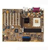
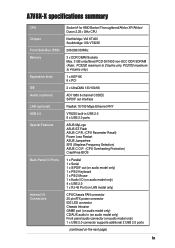
PC2700 maximum to 2 banks only. A7V8X-X specifications summary CPU Chipset Front Side Bus (FSB) Memory Expansion slots IDE Audio (optional) LAN (optional) USB 2.0 Special Features Back Panel I/O Ports Internal I/O Connectors Socket A for AMD Barton/Thoroughbred/Athlon XP/...PDIF out interface Realtek 10/100 Mbps Ethernet PHY VT8235 built-in USB 2.0 6 x USB 2.0 ports ASUS MyLogo ASUS EZ Flash ASUS C.P.R. (CPU Parameter Recall) Power Loss Restart ASUS Jumperfree SFS (Stepless Frequency Selection) ASUS C.O.P. (CPU Overheating Protection) CrashFree BIOS 1 x Parallel 1 x Serial 1 x S/PDIF out (on...
PC2700 maximum to 2 banks only. A7V8X-X specifications summary CPU Chipset Front Side Bus (FSB) Memory Expansion slots IDE Audio (optional) LAN (optional) USB 2.0 Special Features Back Panel I/O Ports Internal I/O Connectors Socket A for AMD Barton/Thoroughbred/Athlon XP/...PDIF out interface Realtek 10/100 Mbps Ethernet PHY VT8235 built-in USB 2.0 6 x USB 2.0 ports ASUS MyLogo ASUS EZ Flash ASUS C.P.R. (CPU Parameter Recall) Power Loss Restart ASUS Jumperfree SFS (Stepless Frequency Selection) ASUS C.O.P. (CPU Overheating Protection) CrashFree BIOS 1 x Parallel 1 x Serial 1 x S/PDIF out (on...
A7V8X-X User Manual
Page 17
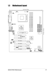
... Chipset Accelerated Graphics Port (AGP) 01 23 45 PCI Slot 1 A7V8X-X PCI Slot 2 PCI Slot 3 PCI Slot 4 PCI Slot 5 ® PCI Slot 6 VIA VT8235 Chipset CR2032 3V Lithium Cell CMOS Power CLRTC Super I/O GAME USBPW56 USB56 IDE_LED SB_PWR 2Mbit Firmware Hub CHASSIS CHA_FAN PANEL PRI_IDE SEC_IDE FLOPPY 30.5cm (12.0in) ASUS A7V8X-X Motherboard 1-7
... Chipset Accelerated Graphics Port (AGP) 01 23 45 PCI Slot 1 A7V8X-X PCI Slot 2 PCI Slot 3 PCI Slot 4 PCI Slot 5 ® PCI Slot 6 VIA VT8235 Chipset CR2032 3V Lithium Cell CMOS Power CLRTC Super I/O GAME USBPW56 USB56 IDE_LED SB_PWR 2Mbit Firmware Hub CHASSIS CHA_FAN PANEL PRI_IDE SEC_IDE FLOPPY 30.5cm (12.0in) ASUS A7V8X-X Motherboard 1-7

A7V8X-X User Manual
Page 25
... describes and illustrates the connectors on the back panel are inadequate, two USB headers (blue headers) are designed to fit these connectors in the package. ATXPWR A7V8X-X ® +3.3VDC -12.0VDC COM PS_ON# COM COM COM -5.0VDC +5.0VDC +5.0VDC A7V8X-X ATX Power Connectors +3.3VDC +3.3VDC COM +5.0VDC... COM +5.0VDC COM PWR_OK +5VSB +12.0VDC If you will need to an ATX 12V power supply. ASUS A7V8X-X Motherboard 1-15 ATX power connectors (20-pin ATXPWR) These connectors connect to replace the power supply in the chassis. USB headers (10...
... describes and illustrates the connectors on the back panel are inadequate, two USB headers (blue headers) are designed to fit these connectors in the package. ATXPWR A7V8X-X ® +3.3VDC -12.0VDC COM PS_ON# COM COM COM -5.0VDC +5.0VDC +5.0VDC A7V8X-X ATX Power Connectors +3.3VDC +3.3VDC COM +5.0VDC... COM +5.0VDC COM PWR_OK +5VSB +12.0VDC If you will need to an ATX 12V power supply. ASUS A7V8X-X Motherboard 1-15 ATX power connectors (20-pin ATXPWR) These connectors connect to replace the power supply in the chassis. USB headers (10...
A7V8X-X User Manual
Page 28
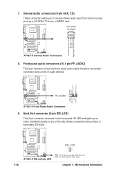
... connectors (10-1 pin FP_AUDIO) This is an interface for the Intel front panel audio cable that allow you to the primary or secondary IDE slots. Chapter 1: Motherboard Information AUX (White) CD (Black) A7V8X-X ® A7V8X-X Internal Audio Connectors 8. A7V8X-X IDE_LED 1-18 ® A7V8X-X IDE Activity LED TIP: If the case-mounted LED does not light...
... connectors (10-1 pin FP_AUDIO) This is an interface for the Intel front panel audio cable that allow you to the primary or secondary IDE slots. Chapter 1: Motherboard Information AUX (White) CD (Black) A7V8X-X ® A7V8X-X Internal Audio Connectors 8. A7V8X-X IDE_LED 1-18 ® A7V8X-X IDE Activity LED TIP: If the case-mounted LED does not light...
A7V8X-X User Manual
Page 30
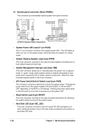
...ON and SOFT OFF, depending on the system power, and blinks when the system is instantly decreased to save power and to the front panel HD LED and lights up when you turn on the BIOS or OS settings. Attach the casemounted suspend switch to the system power LED. ...ExtSMI# Ground PWR Ground Reset Ground A7V8X-X ® A7V8X-X System Panel Connectors IDE_LED SMI Lead Reset SW ATX Power Switch* * Requires an ATX power supply. • System Power LED Lead (3-1 pin PLED) This ...
...ON and SOFT OFF, depending on the system power, and blinks when the system is instantly decreased to save power and to the front panel HD LED and lights up when you turn on the BIOS or OS settings. Attach the casemounted suspend switch to the system power LED. ...ExtSMI# Ground PWR Ground Reset Ground A7V8X-X ® A7V8X-X System Panel Connectors IDE_LED SMI Lead Reset SW ATX Power Switch* * Requires an ATX power supply. • System Power LED Lead (3-1 pin PLED) This ...

A7V8X-X User Manual
Page 52
...] [V/H SYNC+Blank] [DPMS Standby] [DPMS Suspend] [DPMS OFF] [DPMS Reduce ON] HDD Power Down [Disabled] Shuts down any IDE hard disk drives in the Control Panel. Video Off Option [Suspend -> Off ] This field determines when to activate or deactivate the automatic power saving features. Even if installed, your screen saver does...
...] [V/H SYNC+Blank] [DPMS Standby] [DPMS Suspend] [DPMS OFF] [DPMS Reduce ON] HDD Power Down [Disabled] Shuts down any IDE hard disk drives in the Control Panel. Video Off Option [Suspend -> Off ] This field determines when to activate or deactivate the automatic power saving features. Even if installed, your screen saver does...

A7V8X-X User Manual
Page 63
...MIDI Music Synthesizer screen allows you to set to a 6channel speaker system, click the arrow under Select Audio Test Path to display the SoundMAX Control Panel. Choose your setting by clicking the Play Test Noise button. Click the Close button when done. 10. Click the arrow under Speaker Setup to... the Test Listening Environment window. 7. From the taskbar, double-click on the screen indicating the audio path. Click the Apply button. 6. Audio path indicator ASUS A7V8X-X Motherboard 3-5 1. The Listening Environment screen allows you to display a list of options.
...MIDI Music Synthesizer screen allows you to set to a 6channel speaker system, click the arrow under Select Audio Test Path to display the SoundMAX Control Panel. Choose your setting by clicking the Play Test Noise button. Click the Close button when done. 10. Click the arrow under Speaker Setup to... the Test Listening Environment window. 7. From the taskbar, double-click on the screen indicating the audio path. Click the Apply button. 6. Audio path indicator ASUS A7V8X-X Motherboard 3-5 1. The Listening Environment screen allows you to display a list of options.

A7V8X-X User Manual
Page 64
... the Volume Control Advanced button from the Volume Control panel. Check the box opposite Mic2 Select to enable the front panel microphone, if you enable the front panel microphone. 11. The rear panel microphone is automatically disabled when you installed a front panel audio device such as the ASUS iPanel. 3. If you installed an S/PDIF module, click...
... the Volume Control Advanced button from the Volume Control panel. Check the box opposite Mic2 Select to enable the front panel microphone, if you enable the front panel microphone. 11. The rear panel microphone is automatically disabled when you installed a front panel audio device such as the ASUS iPanel. 3. If you installed an S/PDIF module, click...


