
Motherboard DIY Troubleshooting Guide
Page 1
Motherboard A7V400-MX User Guide
Motherboard A7V400-MX User Guide

Motherboard DIY Troubleshooting Guide
Page 3
Features Contents Notices v Safety information vi About this guide vii A7V400-MX specifications summary viii Chapter 1: Product introduction 1.1 Welcome 1-2 1.2 Package contents 1-2 1.3 Special features 1-2 1.3.1 Product highlights 1-2 1.3.2 ASUS unique features 1-3 1.4 Before you proceed 1-4 1.5 Motherboard overview 1-5 1.5.1 Motherboard layout 1-5 1.5.2 Placement direction 1-6 1.5.3 Screw holes 1-6 1.6 Central Processing Unit (CPU 1-7 1.6.1 Overview 1-7 1.6.2 Installing the CPU 1-7 1.7 System memory 1-8 1.7.1 Overview 1-8 1.7.2 Memory configurations 1-8 1.7.3 Installing ...
Features Contents Notices v Safety information vi About this guide vii A7V400-MX specifications summary viii Chapter 1: Product introduction 1.1 Welcome 1-2 1.2 Package contents 1-2 1.3 Special features 1-2 1.3.1 Product highlights 1-2 1.3.2 ASUS unique features 1-3 1.4 Before you proceed 1-4 1.5 Motherboard overview 1-5 1.5.1 Motherboard layout 1-5 1.5.2 Placement direction 1-6 1.5.3 Screw holes 1-6 1.6 Central Processing Unit (CPU 1-7 1.6.1 Overview 1-7 1.6.2 Installing the CPU 1-7 1.7 System memory 1-8 1.7.1 Overview 1-8 1.7.2 Memory configurations 1-8 1.7.3 Installing ...

Motherboard DIY Troubleshooting Guide
Page 6
... sure about the voltage of the electrical outlet you add a device. • Before connecting or removing signal cables from the motherboard, ensure that all the manuals that came with the product, contact a qualified service technician or your retailer. Contact a qualified ...service technician or your retailer. vi Operation safety • Before installing the motherboard and adding devices on a stable surface. • If you detect any damage, contact your area. Safety information Electrical safety •...
... sure about the voltage of the electrical outlet you add a device. • Before connecting or removing signal cables from the motherboard, ensure that all the manuals that came with the product, contact a qualified service technician or your retailer. Contact a qualified ...service technician or your retailer. vi Operation safety • Before installing the motherboard and adding devices on a stable surface. • If you detect any damage, contact your area. Safety information Electrical safety •...

Motherboard DIY Troubleshooting Guide
Page 11
It includes brief descriptions of the motherboard components, and illustrations of the motherboard. Product introduction Chapter 1 This chapter describes the features of the layout, jumper settings, and connectors.
It includes brief descriptions of the motherboard components, and illustrations of the motherboard. Product introduction Chapter 1 This chapter describes the features of the layout, jumper settings, and connectors.

Motherboard DIY Troubleshooting Guide
Page 12
...Socket A processors. Before you for system reconfiguration or future upgrades. Thank you start installing the motherboard and hardware devices on it, check the items in ) ASUS A7V400-MX support CD 40-pin 80-conductor ribbon cable for UltraATA133 IDE drives Ribbon cable for a ... Special features 1.3.1 Product highlights 400MHz FSB support for Athlon™ XP processors The motherboard supports 400MHz front side bus frequency for DVD video. 1-2 Chapter 1: Product introduction The following items. ASUS A7V400-MX motherboard.(Micro-ATX form factor: 9.6 in x 9.6 in your retailer if any of ...
...Socket A processors. Before you for system reconfiguration or future upgrades. Thank you start installing the motherboard and hardware devices on it, check the items in ) ASUS A7V400-MX support CD 40-pin 80-conductor ribbon cable for UltraATA133 IDE drives Ribbon cable for a ... Special features 1.3.1 Product highlights 400MHz FSB support for Athlon™ XP processors The motherboard supports 400MHz front side bus frequency for DVD video. 1-2 Chapter 1: Product introduction The following items. ASUS A7V400-MX motherboard.(Micro-ATX form factor: 9.6 in x 9.6 in your retailer if any of ...
Motherboard DIY Troubleshooting Guide
Page 13
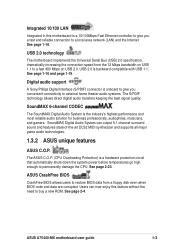
... are corrupted. Users can output 5.1 channel surround sound and features state-of-the-art DLS2 MIDI synthesizer and supports all major game audio technologies. 1.3.2 ASUS unique features ASUS C.O.P. ASUS A7V400-MX motherboard user guide 1-3 See page 1-16. Digital audio support A Sony/Philips Digital Interface (S/PDIF) connector is a hardware protection circuit that automatically shuts down the system...
... are corrupted. Users can output 5.1 channel surround sound and features state-of-the-art DLS2 MIDI synthesizer and supports all major game audio technologies. 1.3.2 ASUS unique features ASUS C.O.P. ASUS A7V400-MX motherboard user guide 1-3 See page 1-16. Digital audio support A Sony/Philips Digital Interface (S/PDIF) connector is a hardware protection circuit that automatically shuts down the system...

Motherboard DIY Troubleshooting Guide
Page 14
...bag that came with a standby power LED. 1.4 Before you proceed Take note of the following precautions before you install motherboard components or change any motherboard settings. • Unplug the power cord from the power supply. Failure to do so may cause severe damage to...components to avoid damaging them due to the motherboard, peripherals, and/or components. When lit, this green LED (SB_PWR) indicates that you uninstall any component, place it on a grounded antistatic pad or in any motherboard component. ® A7V400-MX A7V400-MX Onboard LED SB_PWR ON Standby Power OFF ...
...bag that came with a standby power LED. 1.4 Before you proceed Take note of the following precautions before you install motherboard components or change any motherboard settings. • Unplug the power cord from the power supply. Failure to do so may cause severe damage to...components to avoid damaging them due to the motherboard, peripherals, and/or components. When lit, this green LED (SB_PWR) indicates that you uninstall any component, place it on a grounded antistatic pad or in any motherboard component. ® A7V400-MX A7V400-MX Onboard LED SB_PWR ON Standby Power OFF ...
Motherboard DIY Troubleshooting Guide
Page 15
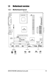
ATX Power Connector PRI_IDE SEC_IDE 24.5cm (9.6in) 1.5 Motherboard overview 1.5.1 Motherboard layout 24.5cm (9.6in) PS/2KBMS T: Mouse B: Keyboard COM1 Socket 462 CPU_FAN DSW FLOPPY DDR DIMM1 (64 bit,184-pin module) DDR ... ® PCI1 A7V400-MX PCI2 CR2032 3V Lithium Cell CMOS Power VIA VT8235CE PCI3 USBPWR56 CLRTC SB_PWR AUX1 CD1 USB56 COM2 Super I/O CHA_FAN1 CHASSIS GAME PANEL 2Mbit Low Pin Count USBPWR12 USBPWR34 2 1 +5V 3 2 +5VSB (Default) USBPWR56 12 23 +5V (Default) +5VSB CLRTC 12 23 Clear CMOS Normal (Default) ASUS A7V400-MX motherboard user guide 1-5
ATX Power Connector PRI_IDE SEC_IDE 24.5cm (9.6in) 1.5 Motherboard overview 1.5.1 Motherboard layout 24.5cm (9.6in) PS/2KBMS T: Mouse B: Keyboard COM1 Socket 462 CPU_FAN DSW FLOPPY DDR DIMM1 (64 bit,184-pin module) DDR ... ® PCI1 A7V400-MX PCI2 CR2032 3V Lithium Cell CMOS Power VIA VT8235CE PCI3 USBPWR56 CLRTC SB_PWR AUX1 CD1 USB56 COM2 Super I/O CHA_FAN1 CHASSIS GAME PANEL 2Mbit Low Pin Count USBPWR12 USBPWR34 2 1 +5V 3 2 +5VSB (Default) USBPWR56 12 23 +5V (Default) +5VSB CLRTC 12 23 Clear CMOS Normal (Default) ASUS A7V400-MX motherboard user guide 1-5

Motherboard DIY Troubleshooting Guide
Page 16
...Place eight (8) screws into the holes indicated by circles to secure the motherboard to do so may cause you physical injury and damage Motherboard components. 1-6 Chapter 1: Product introduction 1.5.2 Placement direction When installing the motherboard to the chassis, make sure to place it in the image below.... Doing so may be more convenient to install major cables, the CPU and modular components before installing the motherboard. It may damage the motherboard. Place this side towards the rear of the chassis as indicated in the correct orientation. Failure to the chassis...
...Place eight (8) screws into the holes indicated by circles to secure the motherboard to do so may cause you physical injury and damage Motherboard components. 1-6 Chapter 1: Product introduction 1.5.2 Placement direction When installing the motherboard to the chassis, make sure to place it in the image below.... Doing so may be more convenient to install major cables, the CPU and modular components before installing the motherboard. It may damage the motherboard. Place this side towards the rear of the chassis as indicated in the correct orientation. Failure to the chassis...

Motherboard DIY Troubleshooting Guide
Page 17
... the lever upwards. If the CPU does not fit, check its alignment and look for CPU installation. ASUS A7V400-MX motherboard user guide 1-7 1.6 Central Processing Unit (CPU) 1.6.1 Overview The motherboard provides a Socket A for bent pins. This corner is usually indicated with the correct orientation. CPU NOTCH... TO INNER CORNER ® A7V400-MX A7V400-MX Socket 462 AMD™ CPU 1.6.2 Installing the CPU Follow these steps to this indicator while orienting the CPU. This motherboard does not support AMD processors with less than 1GHz core speed...
... the lever upwards. If the CPU does not fit, check its alignment and look for CPU installation. ASUS A7V400-MX motherboard user guide 1-7 1.6 Central Processing Unit (CPU) 1.6.1 Overview The motherboard provides a Socket A for bent pins. This corner is usually indicated with the correct orientation. CPU NOTCH... TO INNER CORNER ® A7V400-MX A7V400-MX Socket 462 AMD™ CPU 1.6.2 Installing the CPU Follow these steps to this indicator while orienting the CPU. This motherboard does not support AMD processors with less than 1GHz core speed...

Motherboard DIY Troubleshooting Guide
Page 18
...motherboard has two Double Data Rate (DDR) DIMM sockets that support up to 2GB unbuffered non-ECC PC2700/2100/1600 DDR SDRAM DIMMs. Each DIMM socket is recommended that you obtain memory modules from qualified vendors. For optimum compatibility, it is double-sided. ® A7V400-MX A7V400-MX... 184-Pin DDR DIMM Sockets 1.7.2 Memory configurations You may install single or double-sided 64MB, 128MB, 256MB, 512MB, and 1GB DDR DIMMs to the sockets. DIMM1 DIMM2 1-8 Chapter 1: Product introduction Visit the ASUS website for an updated list of ...
...motherboard has two Double Data Rate (DDR) DIMM sockets that support up to 2GB unbuffered non-ECC PC2700/2100/1600 DDR SDRAM DIMMs. Each DIMM socket is recommended that you obtain memory modules from qualified vendors. For optimum compatibility, it is double-sided. ® A7V400-MX A7V400-MX... 184-Pin DDR DIMM Sockets 1.7.2 Memory configurations You may install single or double-sided 64MB, 128MB, 256MB, 512MB, and 1GB DDR DIMMs to the sockets. DIMM1 DIMM2 1-8 Chapter 1: Product introduction Visit the ASUS website for an updated list of ...
Motherboard DIY Troubleshooting Guide
Page 19
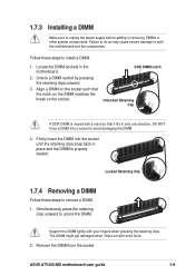
... one direction. 1.7.3 Installing a DIMM Make sure to remove a DIMM. 1. Align a DIMM on the socket. Support the DIMM lightly with extra force. 2. ASUS A7V400-MX motherboard user guide 1-9 Locked Retaining Clip 1.7.4 Removing a DIMM Follow these steps to avoid damaging the DIMM. 4. Firmly insert the DIMM into a socket to install a... system components. DO NOT force a DIMM into the socket until the retaining clips snap back in the motherboard. 2. DDR DIMM notch Unlocked Retaining Clip A DDR DIMM is properly seated. Simultaneously press the retaining clips outward to both the...
... one direction. 1.7.3 Installing a DIMM Make sure to remove a DIMM. 1. Align a DIMM on the socket. Support the DIMM lightly with extra force. 2. ASUS A7V400-MX motherboard user guide 1-9 Locked Retaining Clip 1.7.4 Removing a DIMM Follow these steps to avoid damaging the DIMM. 4. Firmly insert the DIMM into a socket to install a... system components. DO NOT force a DIMM into the socket until the retaining clips snap back in the motherboard. 2. DDR DIMM notch Unlocked Retaining Clip A DDR DIMM is properly seated. Simultaneously press the retaining clips outward to both the...
Motherboard DIY Troubleshooting Guide
Page 20
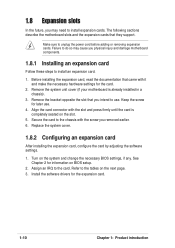
...if any. Refer to the card. Failure to do so may need to install an expansion card. 1. The following sections describe the motherboard slots and the expansion cards that came with the screw you removed earlier. 6. Before installing the expansion card, read the documentation that ...they support. See Chapter 2 for later use . 1.8 Expansion slots In the future, you may cause you physical injury and damage motherboard components. 1.8.1 Installing an expansion card Follow these steps to install expansion cards. Make sure to the chassis with it and make the necessary ...
...if any. Refer to the card. Failure to do so may need to install an expansion card. 1. The following sections describe the motherboard slots and the expansion cards that came with the screw you removed earlier. 6. Before installing the expansion card, read the documentation that ...they support. See Chapter 2 for later use . 1.8 Expansion slots In the future, you may cause you physical injury and damage motherboard components. 1.8.1 Installing an expansion card Follow these steps to install expansion cards. Make sure to the chassis with it and make the necessary ...

Motherboard DIY Troubleshooting Guide
Page 21
IRQ assignments for ISA or PCI devices. shared -- -- -- ASUS A7V400-MX motherboard user guide 1-11 shared -- Standard Interrupt Assignments IRQ Standard Function 0 System Timer 1 Keyboard Controller 2 Programmable Interrupt Controller 3* USB Universal Host Controller 4* Communications Port (...Compatible Mouse Port 13 Numeric Data Processor 14* Ultra ATA Controller 15* Secondary Ultra ATA Controller * These IRQs are usually available for this motherboard PCI slot 1 PCI slot 2 PCI slot 3 AGP slot A B C D shared -- -- -- -- shared -- -- -- --
IRQ assignments for ISA or PCI devices. shared -- -- -- ASUS A7V400-MX motherboard user guide 1-11 shared -- Standard Interrupt Assignments IRQ Standard Function 0 System Timer 1 Keyboard Controller 2 Programmable Interrupt Controller 3* USB Universal Host Controller 4* Communications Port (...Compatible Mouse Port 13 Numeric Data Processor 14* Ultra ATA Controller 15* Secondary Ultra ATA Controller * These IRQs are usually available for this motherboard PCI slot 1 PCI slot 2 PCI slot 3 AGP slot A B C D shared -- -- -- -- shared -- -- -- --

Motherboard DIY Troubleshooting Guide
Page 22
... card, USB card, and other cards that they fit the AGP slot on the card golden fingers to ensure that comply with PCI specifications. This motherboard does not support 3.3V AGP cards. ® A7V400-MX Keyed for 1.5v A7V400-MX Accelerated Graphics Port (AGP) 1.8.4 PCI slots Three 32-bit PCI slots are available on this...
... card, USB card, and other cards that they fit the AGP slot on the card golden fingers to ensure that comply with PCI specifications. This motherboard does not support 3.3V AGP cards. ® A7V400-MX Keyed for 1.5v A7V400-MX Accelerated Graphics Port (AGP) 1.8.4 PCI slots Three 32-bit PCI slots are available on this...
Motherboard DIY Troubleshooting Guide
Page 23
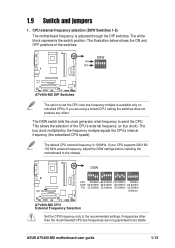
...DIP switches. If your CPU supports 200/166/ 133 MHz external frequency, adjust the DSW settings before installing the motherboard to the chassis. ® A7V400-MX DSW ON ON ON ON CPU AGP PCI 12345 12345 12345 200MHz 166.67MHz 133.33MHz 66.67MHz 66.67MHz... set the CPU core bus frequency multiple is available only on unlocked CPUs. ON OFF DSW ON 12345 A7V400-MX A7V400-MX DIP Switches The option to the recommended settings. ASUS A7V400-MX motherboard user guide 1-13 The white block represents the switch position. Frequencies other than the recommended CPU bus frequencies...
...DIP switches. If your CPU supports 200/166/ 133 MHz external frequency, adjust the DSW settings before installing the motherboard to the chassis. ® A7V400-MX DSW ON ON ON ON CPU AGP PCI 12345 12345 12345 200MHz 166.67MHz 133.33MHz 66.67MHz 66.67MHz... set the CPU core bus frequency multiple is available only on unlocked CPUs. ON OFF DSW ON 12345 A7V400-MX A7V400-MX DIP Switches The option to the recommended settings. ASUS A7V400-MX motherboard user guide 1-13 The white block represents the switch position. Frequencies other than the recommended CPU bus frequencies...
Motherboard DIY Troubleshooting Guide
Page 25
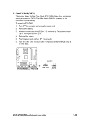
... Clock (RTC) RAM of date, time and system setup parameters in CMOS is powered by the onboard button cell battery. To erase the RTC RAM: 1. A7V400-MX A7V400-MX Clear RTC RAM CLRTC 12 23 Clear CMOS Normal (Default) ASUS A7V400-MX motherboard user guide 1-15 3. Re-install the battery. 5.
... Clock (RTC) RAM of date, time and system setup parameters in CMOS is powered by the onboard button cell battery. To erase the RTC RAM: 1. A7V400-MX A7V400-MX Clear RTC RAM CLRTC 12 23 Clear CMOS Normal (Default) ASUS A7V400-MX motherboard user guide 1-15 3. Re-install the battery. 5.

Motherboard DIY Troubleshooting Guide
Page 26
... (USB) ports are available for connecting USB 2.0 devices. 8. Serial port. 1.10 Connectors This section describes and illustrates the rear panel and internal connectors on the motherboard. 1.10.1 Rear panel connectors 1 2 3 4 5 6 11 10 9 8 7 1. PS/2 mouse port. This green 6-pin connector is for a PS/2 mouse. 2. PS/2 keyboard port. This Line In (light blue...
... (USB) ports are available for connecting USB 2.0 devices. 8. Serial port. 1.10 Connectors This section describes and illustrates the rear panel and internal connectors on the motherboard. 1.10.1 Rear panel connectors 1 2 3 4 5 6 11 10 9 8 7 1. PS/2 mouse port. This green 6-pin connector is for a PS/2 mouse. 2. PS/2 keyboard port. This Line In (light blue...
Motherboard DIY Troubleshooting Guide
Page 27
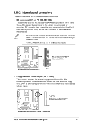
... IDE connector is removed to prevent incorrect insertion when using ribbon cables with pin 5 plug.) ® A7V400-MX FLOPPY NOTE: Orient the red markings on the floppy ribbon cable to PIN 1. PIN 1 A7V400-MX Floppy Disk Drive Connector ASUS A7V400-MX motherboard user guide 1-17 This prevents incorrect orientation when you connect the cables. • For UltraATA133 IDE...
... IDE connector is removed to prevent incorrect insertion when using ribbon cables with pin 5 plug.) ® A7V400-MX FLOPPY NOTE: Orient the red markings on the floppy ribbon cable to PIN 1. PIN 1 A7V400-MX Floppy Disk Drive Connector ASUS A7V400-MX motherboard user guide 1-17 This prevents incorrect orientation when you connect the cables. • For UltraATA133 IDE...
Motherboard DIY Troubleshooting Guide
Page 29
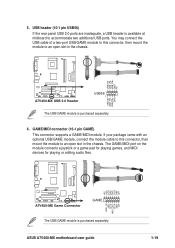
USB+5V USB_P6USB_P6+ GND NC USB+5V USB_P5USB_P5+ GND ® A7V400-MX A7V400-MX USB 2.0 Header USB56 1 The USB/GAME module is available at midboard to accommodate two additional USB ports. GAME/MIDI connector (16-1 pin GAME) This connector ... may connect the USB cable of a two-port USB/GAME module to this connector, then mount the module to an open slot in the chassis. ASUS A7V400-MX motherboard user guide MIDI_IN J2B2 J2CY MIDI_OUT J2CX J2B1 +5V +5V J1B2 J1CY GND GND J1CX J1B1 +5V 1-19 If your package came with an optional...
USB+5V USB_P6USB_P6+ GND NC USB+5V USB_P5USB_P5+ GND ® A7V400-MX A7V400-MX USB 2.0 Header USB56 1 The USB/GAME module is available at midboard to accommodate two additional USB ports. GAME/MIDI connector (16-1 pin GAME) This connector ... may connect the USB cable of a two-port USB/GAME module to this connector, then mount the module to an open slot in the chassis. ASUS A7V400-MX motherboard user guide MIDI_IN J2B2 J2CY MIDI_OUT J2CX J2B1 +5V +5V J1B2 J1CY GND GND J1CX J1B1 +5V 1-19 If your package came with an optional...


