Owners Manual
Page 2
Contents Operating Instructions WARNING WARNING 2 CAUTION 3 PRECAUTIONS 3 Getting Started Feature 4 Rear Camera Operation Turning the Rear Camera On and Off 5 Changing the Rear Image Configuration .......... 5 Front Camera Operation Turning the Front Camera On and Off 6 Changing the Front Image Configuration ......... 6 Installation and Connections Mounting the Rear Camera (HCE-C200R) ...... 7 Mounting the Front Camera (HCE-C200F) (If HCE-C200F is purchased 10 Connections 11 System Example 12 Confirmation 14 Information Specifications 15 ENGLISH 1-EN
Contents Operating Instructions WARNING WARNING 2 CAUTION 3 PRECAUTIONS 3 Getting Started Feature 4 Rear Camera Operation Turning the Rear Camera On and Off 5 Changing the Rear Image Configuration .......... 5 Front Camera Operation Turning the Front Camera On and Off 6 Changing the Front Image Configuration ......... 6 Installation and Connections Mounting the Rear Camera (HCE-C200R) ...... 7 Mounting the Front Camera (HCE-C200F) (If HCE-C200F is purchased 10 Connections 11 System Example 12 Confirmation 14 Information Specifications 15 ENGLISH 1-EN
Owners Manual
Page 3
...of the vehicle and cause an accident. Arrange wiring and cables in the chassis for installations or ground connections. The TOPVIEW FRONT/REAR CAMERA assists the driver in fire or electric shock. DO NOT DISASSEMBLE OR ALTER. Viewing the display may obstruct forward vision or hamper movement etc.... BEFORE WIRING, DISCONNECT THE CABLE FROM THE NEGATIVE BATTERY TERMINAL. Failure to do so may result in checking behind and around by the rear camera are not sure.) Failure to do so may result in electric shock or injury due to do so may result in fire, etc. ...
...of the vehicle and cause an accident. Arrange wiring and cables in the chassis for installations or ground connections. The TOPVIEW FRONT/REAR CAMERA assists the driver in fire or electric shock. DO NOT DISASSEMBLE OR ALTER. Viewing the display may obstruct forward vision or hamper movement etc.... BEFORE WIRING, DISCONNECT THE CABLE FROM THE NEGATIVE BATTERY TERMINAL. Failure to do so may result in checking behind and around by the rear camera are not sure.) Failure to do so may result in electric shock or injury due to do so may result in fire, etc. ...
Owners Manual
Page 4
...car body. When in doubt, consult your Alpine dealer. • In some cases, to the positive (+) of the factory installed components (e.g. The same images appear on the display as this to a power cable of the rear lamp, but not to attach the camera, a hole must be used independently, ...means important instructions. Use of other fitting. Return it to your HCE-C200R/HCE-C200F. Doing so could cause the camera direction to shift, or the camera mounting to the unit in place. This will reduce any excess pressure to the camera or the mounting, as on -board computer). Be sure to ...
...car body. When in doubt, consult your Alpine dealer. • In some cases, to the positive (+) of the factory installed components (e.g. The same images appear on the display as this to a power cable of the rear lamp, but not to attach the camera, a hole must be used independently, ...means important instructions. Use of other fitting. Return it to your HCE-C200R/HCE-C200F. Doing so could cause the camera direction to shift, or the camera mounting to the unit in place. This will reduce any excess pressure to the camera or the mounting, as on -board computer). Be sure to ...
Owners Manual
Page 5
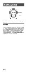
Getting Started ON/OFF MODE Operation is connected to the optional TOPVIEW FRONT CAMERA (HCE-C200F), you on the equipped monitor in the case of the TOPVIEW REAR CAMERA (HCE-C200R) and the equipped monitor. Feature When reversing the car, you can also check conditions ahead of you can check behind and around the car with the assistance of a difficult-to-judge road or cross-roads. 4-EN If the TOPVIEW REAR CAMERA is carried out by pressing the switch, or shifting the gear lever.
Getting Started ON/OFF MODE Operation is connected to the optional TOPVIEW FRONT CAMERA (HCE-C200F), you on the equipped monitor in the case of the TOPVIEW REAR CAMERA (HCE-C200R) and the equipped monitor. Feature When reversing the car, you can also check conditions ahead of you can check behind and around the car with the assistance of a difficult-to-judge road or cross-roads. 4-EN If the TOPVIEW REAR CAMERA is carried out by pressing the switch, or shifting the gear lever.
Owners Manual
Page 6
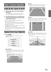
... • Depending on where the unit is used to turn the front camera on gear lever operation. 2 If you want to the reverse position (reversing). Panorama View: Displays a general perspective of the car rear and surround interruption depends on /off depends on the position of the car...position other than reverse (reversing), the monitor returns to the previous screen. • Refer also to the Owner's Manual of centre. How the rear camera turns on/off . Corner View: Displays a divided image left and right directional view. Use this when to determine the car's position in ...
... • Depending on where the unit is used to turn the front camera on gear lever operation. 2 If you want to the reverse position (reversing). Panorama View: Displays a general perspective of the car rear and surround interruption depends on /off depends on the position of the car...position other than reverse (reversing), the monitor returns to the previous screen. • Refer also to the Owner's Manual of centre. How the rear camera turns on/off . Corner View: Displays a divided image left and right directional view. Use this when to determine the car's position in ...
Owners Manual
Page 8
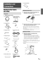
...Velcro fastener (soft side) ! to the floor carpet, do so without the Velcro fastener (soft side) ! Installation and Connections Mounting the Rear Camera (HCE-C200R) Preparation 1 Check accessory parts. 1 Rear camera (1m) 2 Power unit (ACC:2m, GND:2m, Reverse In:6m, Reverse out:2m) % Cord clamp (Switch) x 3 Installing ...the Switch 1 Attach the switch # according to the bottom of the switch, then peel off any dust, oil, etc., on the rear of the instrument panel, or under a seat. Attach the supplied switch adhesive sheet #. attached. • It is recommended to the ...
...Velcro fastener (soft side) ! to the floor carpet, do so without the Velcro fastener (soft side) ! Installation and Connections Mounting the Rear Camera (HCE-C200R) Preparation 1 Check accessory parts. 1 Rear camera (1m) 2 Power unit (ACC:2m, GND:2m, Reverse In:6m, Reverse out:2m) % Cord clamp (Switch) x 3 Installing ...the Switch 1 Attach the switch # according to the bottom of the switch, then peel off any dust, oil, etc., on the rear of the instrument panel, or under a seat. Attach the supplied switch adhesive sheet #. attached. • It is recommended to the ...
Owners Manual
Page 9
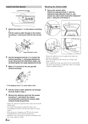
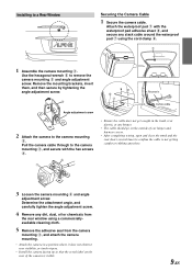
...waterproof pad 7 using the cord clamp 9. 1 1 Attach the camera 1 to the Rear Garnish Securing the Camera Cable 1 Secure the camera cable. Determine the attachment angle, and carefully tighten the angle adjustment screw. 3 Make a 13 mm hole in the rear garnish camera mounting. 2.5* 13 • Ensure the cable does not get...on the outside of car hinges and harness covers. • After completing wiring, open and close the trunk and the rear doors several times to the camera mounting 3, and secure with the waterproof pad adhesive sheet 8, and secure any hinges. • The cable should go ...
...waterproof pad 7 using the cord clamp 9. 1 1 Attach the camera 1 to the Rear Garnish Securing the Camera Cable 1 Secure the camera cable. Determine the attachment angle, and carefully tighten the angle adjustment screw. 3 Make a 13 mm hole in the rear garnish camera mounting. 2.5* 13 • Ensure the cable does not get...on the outside of car hinges and harness covers. • After completing wiring, open and close the trunk and the rear doors several times to the camera mounting 3, and secure with the waterproof pad adhesive sheet 8, and secure any hinges. • The cable should go ...
Owners Manual
Page 10
...is visible. 9-EN Pull the camera cable through to the camera mounting 3, and secure with the waterproof pad adhesive sheet 8, and secure any dirt, dust, oil or chemicals from the camera mounting 3, and attach the camera mounting. • Attach the camera in the trunk, rear door(s) or any hinges. &#...8226; The cable should go on the rear of car hinges and harness covers. • After completing wiring, ...
...is visible. 9-EN Pull the camera cable through to the camera mounting 3, and secure with the waterproof pad adhesive sheet 8, and secure any dirt, dust, oil or chemicals from the camera mounting 3, and attach the camera mounting. • Attach the camera in the trunk, rear door(s) or any hinges. &#...8226; The cable should go on the rear of car hinges and harness covers. • After completing wiring, ...
Owners Manual
Page 12
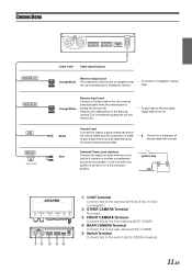
...12 3 4 5 1 V.OUT Terminal Connect this to the camera terminal of the monitor or navigation. 2 OTHER CAMERA Terminal Not used. 3 FRONT CAMERA Terminal Connect this to the front camera (HCE-C200F) 4 REAR CAMERA Terminal Connect this to the rear camera (HCE-C200R) 5 Switch Terminal Connect this lead to a metal part of ... transmission is securely fastened using the sheet metal screw provided. Make sure the connection is made ---to the switch (HCE-C200R included) 11-EN Connections REVERSE OUT REVERSE IN GND IGNITION Fuse (7.5A) Cable Color Cable Specifications Orange/Black Reverse ...
...12 3 4 5 1 V.OUT Terminal Connect this to the camera terminal of the monitor or navigation. 2 OTHER CAMERA Terminal Not used. 3 FRONT CAMERA Terminal Connect this to the front camera (HCE-C200F) 4 REAR CAMERA Terminal Connect this to the rear camera (HCE-C200R) 5 Switch Terminal Connect this lead to a metal part of ... transmission is securely fastened using the sheet metal screw provided. Make sure the connection is made ---to the switch (HCE-C200R included) 11-EN Connections REVERSE OUT REVERSE IN GND IGNITION Fuse (7.5A) Cable Color Cable Specifications Orange/Black Reverse ...
Owners Manual
Page 13
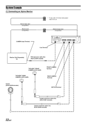
... CAMERA (HCE-C200F) TOPVIEW REAR CAMERA (HCE-C200R) FRONT CAMERA Terminal REAR CAMERA Terminal Switch (HCE-C200R included) SWITCH Terminal Camera extension cable (4m) (HCE-C200F included) Camera extension cable (7m) (HCE-C200R included) 12-EN To plus side of the back lamp signal lead of the car Reverse Output Lead (Orange/Black) CAMERA Input Terminal V.out Terminal Monitor (Sold Separately) etc. System Example (1) Connecting an Alpine...
... CAMERA (HCE-C200F) TOPVIEW REAR CAMERA (HCE-C200R) FRONT CAMERA Terminal REAR CAMERA Terminal Switch (HCE-C200R included) SWITCH Terminal Camera extension cable (4m) (HCE-C200F included) Camera extension cable (7m) (HCE-C200R included) 12-EN To plus side of the back lamp signal lead of the car Reverse Output Lead (Orange/Black) CAMERA Input Terminal V.out Terminal Monitor (Sold Separately) etc. System Example (1) Connecting an Alpine...
Owners Manual
Page 14
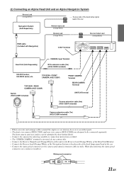
(2) Connecting an Alpine Head Unit and an Alpine Navigation System Reverse Lead (Orange/White) ---- When disconnecting the water-proof connector, use a minus screwdriver. To ...IVA-W200 series, etc. The front camera and rear camera can be connected separately. Water-proof connector 13-EN TOPVIEW FRONT CAMERA (HCE-C200F) TOPVIEW REAR CAMERA (HCE-C200R) Switch (HCE-C200R included) FRONT CAMERA Terminal REAR CAMERA Terminal SWITCH Terminal Camera extension cable (4m) (HCE-C200F included) Camera extension cable (7m) (HCE-C200R included) • When you route and...
(2) Connecting an Alpine Head Unit and an Alpine Navigation System Reverse Lead (Orange/White) ---- When disconnecting the water-proof connector, use a minus screwdriver. To ...IVA-W200 series, etc. The front camera and rear camera can be connected separately. Water-proof connector 13-EN TOPVIEW FRONT CAMERA (HCE-C200F) TOPVIEW REAR CAMERA (HCE-C200R) Switch (HCE-C200R included) FRONT CAMERA Terminal REAR CAMERA Terminal SWITCH Terminal Camera extension cable (4m) (HCE-C200F included) Camera extension cable (7m) (HCE-C200R included) • When you route and...
Owners Manual
Page 16
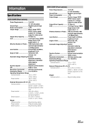
Information Specifications HCE-C200R (Rear camera) Power Requirements 14.4V DC (11-16V allowable) Ground Type Negative ground type Power Consumption 1.7W Output Image Mirror image, VBCS (NTSC Colour signal system) ... (3-15/16" x 1-31/32" x 31/32") (except projection) Switch section 29 x 38.5 x 13.6mm (1-1/8" x 1-1/2" x 17/32") Weight Camera section 80g (including cable) Power section 270g (including cable) Switch section 50g (including cable) HCE-C200F (Front camera) Power Requirements 14.4V DC (11-16V allowable) Ground Type Negative ground type Power Consumption 1.7W Output...
Information Specifications HCE-C200R (Rear camera) Power Requirements 14.4V DC (11-16V allowable) Ground Type Negative ground type Power Consumption 1.7W Output Image Mirror image, VBCS (NTSC Colour signal system) ... (3-15/16" x 1-31/32" x 31/32") (except projection) Switch section 29 x 38.5 x 13.6mm (1-1/8" x 1-1/2" x 17/32") Weight Camera section 80g (including cable) Power section 270g (including cable) Switch section 50g (including cable) HCE-C200F (Front camera) Power Requirements 14.4V DC (11-16V allowable) Ground Type Negative ground type Power Consumption 1.7W Output...


