Aspire X1200 / X3200 Service Guide
Page 7
... Panel 34 Removing the Font Bezel 35 Removing the Heat Sink Fan Assembly 36 Removing the Processor 38 Removing the Optical Drive 40 Removing the Hard Disk Drive 42 Removing the Power Supply 46 Removing the Memory Modules 49 Removing the PCI Card 51 Removing the Front I/O and Card Reader Boards... Block Diagram and Board Layout 69 System Block Diagram 69 Board Layout 70 Mainboard 70 System Jumpers 71 FRU (Field Replaceable Unit) List 73 Aspire ASX1200/ ASX3200 Exploded Diagram 74 Aspire ASX1200/ ASX3200 FRU List (81.3V001.010G) 75 Technical Specifications 83 vii
... Panel 34 Removing the Font Bezel 35 Removing the Heat Sink Fan Assembly 36 Removing the Processor 38 Removing the Optical Drive 40 Removing the Hard Disk Drive 42 Removing the Power Supply 46 Removing the Memory Modules 49 Removing the PCI Card 51 Removing the Front I/O and Card Reader Boards... Block Diagram and Board Layout 69 System Block Diagram 69 Board Layout 70 Mainboard 70 System Jumpers 71 FRU (Field Replaceable Unit) List 73 Aspire ASX1200/ ASX3200 Exploded Diagram 74 Aspire ASX1200/ ASX3200 FRU List (81.3V001.010G) 75 Technical Specifications 83 vii
Aspire X1200 / X3200 Service Guide
Page 9
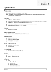
... nForce MCP78 Memory subsystem T Supports up to two DDR2-667 registered ECC modules Media storage T DVD-ROM SATA drive T Super-Multi SATA DVD drive T 160 GB SATA hard disk drive Serial ATA controller T Embedded SATA2 controller T Two SATA ports Networking T One Gigabit Ethernet LAN port (RJ-45) PCI I/O T One PCI Express x16 bus...
... nForce MCP78 Memory subsystem T Supports up to two DDR2-667 registered ECC modules Media storage T DVD-ROM SATA drive T Super-Multi SATA DVD drive T 160 GB SATA hard disk drive Serial ATA controller T Embedded SATA2 controller T Two SATA ports Networking T One Gigabit Ethernet LAN port (RJ-45) PCI I/O T One PCI Express x16 bus...
Aspire X1200 / X3200 Service Guide
Page 20
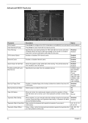
...Option When set to fast, the motherboard chipset controls the operation of Gate A20. Hard Disk Boot Priority Press Enter to boot the system. If enabled, BIOS will decrease the time needed to select hard disk boot device priority. But when set to normal, a pin in Msec, before ... 40 Disabled to determine whether they have pressed continuously. 1000 12 Chapter 2 Virus Warning Specifies the virus warning feature for Num Lock. CDROM, Hard Disk, NVIDIA Boot Age, Floppy, ZIP, USB-FDD, USB-ZIP, USBCDROM, USBHDD, Legacy LAN, Disabled Boot Up Floppy Seek Enables or disables ...
...Option When set to fast, the motherboard chipset controls the operation of Gate A20. Hard Disk Boot Priority Press Enter to boot the system. If enabled, BIOS will decrease the time needed to select hard disk boot device priority. But when set to normal, a pin in Msec, before ... 40 Disabled to determine whether they have pressed continuously. 1000 12 Chapter 2 Virus Warning Specifies the virus warning feature for Num Lock. CDROM, Hard Disk, NVIDIA Boot Age, Floppy, ZIP, USB-FDD, USB-ZIP, USBCDROM, USBHDD, Legacy LAN, Disabled Boot Up Floppy Seek Enables or disables ...
Aspire X1200 / X3200 Service Guide
Page 22
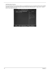
Hard Disk Boot Priority The Hard Disk Boot Priority submenu allows you to move it up or down on the list. Use the up or down arrow key to select a hard drive, then press the key or the key to specify the sequence of loading the OS from the installed hard drives. l 14 Chapter 2
Hard Disk Boot Priority The Hard Disk Boot Priority submenu allows you to move it up or down on the list. Use the up or down arrow key to select a hard drive, then press the key or the key to specify the sequence of loading the OS from the installed hard drives. l 14 Chapter 2
Aspire X1200 / X3200 Service Guide
Page 26
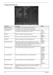
... on the PCI Express slot or PCI slot. Enables or disables the built-in ECP mode. When enabled, the BIOS will automatically detect if your hard disk supports block transfers and set to 64 KB of data can be transferred per interrupt when block transfers are enabled. Select an operating mode for...
... on the PCI Express slot or PCI slot. Enables or disables the built-in ECP mode. When enabled, the BIOS will automatically detect if your hard disk supports block transfers and set to 64 KB of data can be transferred per interrupt when block transfers are enabled. Select an operating mode for...
Aspire X1200 / X3200 Service Guide
Page 27
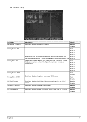
... disables DMA (Direct Memory Access) transfers for faster data recovery and read/write timing that reduces hard disk activity time. Enabled Disabled Chapter 2 19 Mode 0 to prefetch data from the IDE drive. This results in better hard disk performance. Enabled Disabled Enables or disables the IDE controller to 4 provide progressive increase of performance. Enabled...
... disables DMA (Direct Memory Access) transfers for faster data recovery and read/write timing that reduces hard disk activity time. Enabled Disabled Chapter 2 19 Mode 0 to prefetch data from the IDE drive. This results in better hard disk performance. Enabled Disabled Enables or disables the IDE controller to 4 provide progressive increase of performance. Enabled...
Aspire X1200 / X3200 Service Guide
Page 30
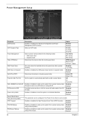
... Enabled Disabled Enabled Disabled Enabled This parameter can be configured if the Power-On by Alarm Day of system power button. Set a time when the hard disk drives will wake system from a power saving mode using a PS2 mouse. Enables or disables to enable. Power Management Setup Parameter ACPI function ACPI Suspend Type...
... Enabled Disabled Enabled Disabled Enabled This parameter can be configured if the Power-On by Alarm Day of system power button. Set a time when the hard disk drives will wake system from a power saving mode using a PS2 mouse. Enables or disables to enable. Power Management Setup Parameter ACPI function ACPI Suspend Type...
Aspire X1200 / X3200 Service Guide
Page 50
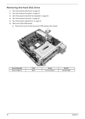
See "Removing the Heat Sink Fan Assembly" on page 38. 5. See "Removing the Processor" on page 36. 4. Screw (Quantity) #6-32 L5 BZN (1) Color Black Torque 5.5 to the chassis. See "Removing the Side Panel" on page 40. 6. a. Remove the screw (A) that secures the HDD bracket to 6.5 kgf-cm Part No. 86.00J07.B60 42 Chapter 3 See "Removing the Optical Drive" on page 34. 2. See "Removing the Font Bezel" on page 35. 3. Removing the Hard Disk Drive 1. Remove the HDD-ODD bracket.
See "Removing the Heat Sink Fan Assembly" on page 38. 5. See "Removing the Processor" on page 36. 4. Screw (Quantity) #6-32 L5 BZN (1) Color Black Torque 5.5 to the chassis. See "Removing the Side Panel" on page 40. 6. a. Remove the screw (A) that secures the HDD bracket to 6.5 kgf-cm Part No. 86.00J07.B60 42 Chapter 3 See "Removing the Optical Drive" on page 34. 2. See "Removing the Font Bezel" on page 35. 3. Removing the Hard Disk Drive 1. Remove the HDD-ODD bracket.
Aspire X1200 / X3200 Service Guide
Page 54
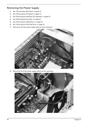
See "Removing the Side Panel" on page 38. 5. See "Removing the Processor" on page 34. 2. See "Removing the Hard Disk Drive" on page 36. 4. Disconnect the 24-pin power supply cable from the mainboard. 8. See "Removing the Heat Sink Fan Assembly" on page 42. 7. Disconnect the 8-pin power supply cable from the mainboard. 46 Chapter 3 See "Removing the Optical Drive" on page 35. 3. See "Removing the Font Bezel" on page 40. 6. Removing the Power Supply 1.
See "Removing the Side Panel" on page 38. 5. See "Removing the Processor" on page 34. 2. See "Removing the Hard Disk Drive" on page 36. 4. Disconnect the 24-pin power supply cable from the mainboard. 8. See "Removing the Heat Sink Fan Assembly" on page 42. 7. Disconnect the 8-pin power supply cable from the mainboard. 46 Chapter 3 See "Removing the Optical Drive" on page 35. 3. See "Removing the Font Bezel" on page 40. 6. Removing the Power Supply 1.
Aspire X1200 / X3200 Service Guide
Page 57
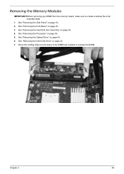
Removing the Memory Modules IMPORTANT:Before removing any DIMM from the memory board, make sure to create a backup file of the DIMM slot outward to release the DIMM. See "Removing the Side Panel" on page 35. 3. Chapter 3 49 See "Removing the Font Bezel" on page 34. 2. See "Removing the Optical Drive" on page 42. 7. See "Removing the Hard Disk Drive" on page 40. 6. See "Removing the Processor" on page 36. 4. Press the holding clips on both sides of all important data. 1. See "Removing the Heat Sink Fan Assembly" on page 38. 5.
Removing the Memory Modules IMPORTANT:Before removing any DIMM from the memory board, make sure to create a backup file of the DIMM slot outward to release the DIMM. See "Removing the Side Panel" on page 35. 3. Chapter 3 49 See "Removing the Font Bezel" on page 34. 2. See "Removing the Optical Drive" on page 42. 7. See "Removing the Hard Disk Drive" on page 40. 6. See "Removing the Processor" on page 36. 4. Press the holding clips on both sides of all important data. 1. See "Removing the Heat Sink Fan Assembly" on page 38. 5.
Aspire X1200 / X3200 Service Guide
Page 59
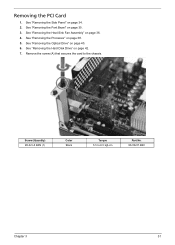
See "Removing the Heat Sink Fan Assembly" on page 38. 5. Remove the screw (A) that secures the card to 6.5 kgf-cm Part No. 86.00J07.B60 Chapter 3 51 See "Removing the Processor" on page 36. 4. Screw (Quantity) #6-32 L5 BZN (1) Color Black Torque 5.5 to the chassis. Removing the PCI Card 1. See "Removing the Optical Drive" on page 35. 3. See "Removing the Font Bezel" on page 40. 6. See "Removing the Hard Disk Drive" on page 34. 2. See "Removing the Side Panel" on page 42. 7.
See "Removing the Heat Sink Fan Assembly" on page 38. 5. Remove the screw (A) that secures the card to 6.5 kgf-cm Part No. 86.00J07.B60 Chapter 3 51 See "Removing the Processor" on page 36. 4. Screw (Quantity) #6-32 L5 BZN (1) Color Black Torque 5.5 to the chassis. Removing the PCI Card 1. See "Removing the Optical Drive" on page 35. 3. See "Removing the Font Bezel" on page 40. 6. See "Removing the Hard Disk Drive" on page 34. 2. See "Removing the Side Panel" on page 42. 7.
Aspire X1200 / X3200 Service Guide
Page 61
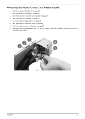
See "Removing the Memory Modules" on page 42. 7. Disconnect one end of the three USB (1, 2, and 4), audio (2), and 1394 (5) cables from the rear of the I /O and Card Reader Boards 1. Removing the Front I /O and card reader boards. See "Removing the Hard Disk Drive" on page 49. 8. Chapter 3 53 See "Removing the Heat Sink Fan Assembly" on page 38. 5. See "Removing the Processor" on page 36. 4. See "Removing the Optical Drive" on page 34. 2. See "Removing the Side Panel" on page 40. 6. See "Removing the Font Bezel" on page 35. 3.
See "Removing the Memory Modules" on page 42. 7. Disconnect one end of the three USB (1, 2, and 4), audio (2), and 1394 (5) cables from the rear of the I /O and Card Reader Boards 1. Removing the Front I /O and card reader boards. See "Removing the Hard Disk Drive" on page 49. 8. Chapter 3 53 See "Removing the Heat Sink Fan Assembly" on page 38. 5. See "Removing the Processor" on page 36. 4. See "Removing the Optical Drive" on page 34. 2. See "Removing the Side Panel" on page 40. 6. See "Removing the Font Bezel" on page 35. 3.
Aspire X1200 / X3200 Service Guide
Page 65
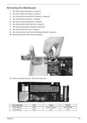
... Card Reader Boards" on page 34. 2. See "Removing the Side Panel" on page 53. 10. See "Removing the Processor" on page 42. 7. See "Removing the Hard Disk Drive" on page 38. 5. Disconnect the LED cable from the rear panel. See "Removing the Heat Sink Fan Assembly" on page 49. 8. Removing the Mainboard...
... Card Reader Boards" on page 34. 2. See "Removing the Side Panel" on page 53. 10. See "Removing the Processor" on page 42. 7. See "Removing the Hard Disk Drive" on page 38. 5. Disconnect the LED cable from the rear panel. See "Removing the Heat Sink Fan Assembly" on page 49. 8. Removing the Mainboard...
Aspire X1200 / X3200 Service Guide
Page 85
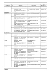
... WD5000AAJS-22A8B0 KH.50008.009 WD WD5000AAJS-22A8B0 LF F/ W:01.03A01 Chapter 6 77 Component Sempron, 45W Optical drive DVD-RW drive Hard disk drive 160 GB 250 GB 320 GB 500 GB QTY Part Name 1 CPU AMD 2.2G SDH1250IAA4DP SEMPRON LE-1250 1 CPU AMD 2.5G G2 SDH1300IAA4DP SEMPRON LE- 1300 Description IC CPU... SEMPRON LE-1250 2.2G IC CPU SEMPRON LE-1300 2.5G G2 Acer Part Number KC.SLE02.125 KC.SLE02.130 1 DVD-RW DRIVE...
... WD5000AAJS-22A8B0 KH.50008.009 WD WD5000AAJS-22A8B0 LF F/ W:01.03A01 Chapter 6 77 Component Sempron, 45W Optical drive DVD-RW drive Hard disk drive 160 GB 250 GB 320 GB 500 GB QTY Part Name 1 CPU AMD 2.2G SDH1250IAA4DP SEMPRON LE-1250 1 CPU AMD 2.5G G2 SDH1300IAA4DP SEMPRON LE- 1300 Description IC CPU... SEMPRON LE-1250 2.2G IC CPU SEMPRON LE-1300 2.5G G2 Acer Part Number KC.SLE02.125 KC.SLE02.130 1 DVD-RW DRIVE...


