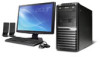
Acer Veriton M430 Desktop Service Guide
Page 7
...Hard Disk Drive 35 Removing the Optical Drive 37 Remove System FAN 39 Removing the Power Supply 40 Removing the OBR Cable and Intrusion Alarm Cable 41 Removing the Card Reader 43 Removing the Internal Speaker 44 Removing the Mainboard 45 Removing Other Side Pannel 47 Removing the Front I/O and USB Assembly 48 Removing the Power Switch and LED Cable Assembly 50 System Troubleshooting 52 Hardware Diagnostic Procedure 52 System Check Procedures 53 Beep Codes 54 Checkpoints 55 BIOS Recovery 58 Jumper and Connector Information 59 M/B Placement 59 Jumper Setting...
...Hard Disk Drive 35 Removing the Optical Drive 37 Remove System FAN 39 Removing the Power Supply 40 Removing the OBR Cable and Intrusion Alarm Cable 41 Removing the Card Reader 43 Removing the Internal Speaker 44 Removing the Mainboard 45 Removing Other Side Pannel 47 Removing the Front I/O and USB Assembly 48 Removing the Power Switch and LED Cable Assembly 50 System Troubleshooting 52 Hardware Diagnostic Procedure 52 System Check Procedures 53 Beep Codes 54 Checkpoints 55 BIOS Recovery 58 Jumper and Connector Information 59 M/B Placement 59 Jumper Setting...
Acer Veriton M430 Desktop Service Guide
Page 9
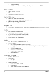
... enabled always when plug-in 2 same memory size DDRIII memory module Hard disk drive • Support up to two SATA ports • 3.5" • Capacity and models are listed on AVLC Optical disk drive • Support one SATA 5.25" standard ODD • Support DVD-ROM, DVD-SuperMulti, BD-combo, BD-rewrite • Maximum ODD depth to 185mm with bezel • Models are listed on AVLC Graphics card • No mechanical retriction to support for double slot, full length graphics cards...
... enabled always when plug-in 2 same memory size DDRIII memory module Hard disk drive • Support up to two SATA ports • 3.5" • Capacity and models are listed on AVLC Optical disk drive • Support one SATA 5.25" standard ODD • Support DVD-ROM, DVD-SuperMulti, BD-combo, BD-rewrite • Maximum ODD depth to 185mm with bezel • Models are listed on AVLC Graphics card • No mechanical retriction to support for double slot, full length graphics cards...
Acer Veriton M430 Desktop Service Guide
Page 10
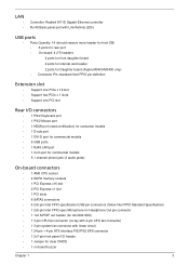
... controller RJ-45 Back panel port with Link/Activity LEDs USB ports • Ports Quantity: 14 (should reserve more header for front DB) • 6 ports for rear port • On-board: 4 2*5 headers 4 ports for front daughter board 2 ports for internal card reader 2 ports for Daughter board (Aspire M5400/M3400 only) • Connector Pin: standard Intel FPIO pin definition Extension slot • Support one PCIe x 16 slot • Support two PCIe x 1 slots • Support one PCI slot Rear I/O connectors • 1 PS/2 Keyboard port • 1 PS/2 Mouse port • 1 HDMI port (need...
... controller RJ-45 Back panel port with Link/Activity LEDs USB ports • Ports Quantity: 14 (should reserve more header for front DB) • 6 ports for rear port • On-board: 4 2*5 headers 4 ports for front daughter board 2 ports for internal card reader 2 ports for Daughter board (Aspire M5400/M3400 only) • Connector Pin: standard Intel FPIO pin definition Extension slot • Support one PCIe x 16 slot • Support two PCIe x 1 slots • Support one PCI slot Rear I/O connectors • 1 PS/2 Keyboard port • 1 PS/2 Mouse port • 1 HDMI port (need...
Acer Veriton M430 Desktop Service Guide
Page 11
• 2 reserved 2-pin GPIO connector • 1 2x4 internal speaker header • 1 2-pin OBR header • 1 2x10-pin TPM module connector • 1 FDD slot • 1 2-pin intrusion alarm header • 1 Serial port header • 1 Parallel port header System BIOS • Size: 8Mbit • AMI Kernel with Acer skin/copyright Power supply • 300W/500W in stable mode (Acer Assign System Power Unit) • Support 82+ PSU for EnergyStar 5.0 complaint • Design for...
• 2 reserved 2-pin GPIO connector • 1 2x4 internal speaker header • 1 2-pin OBR header • 1 2x10-pin TPM module connector • 1 FDD slot • 1 2-pin intrusion alarm header • 1 Serial port header • 1 Parallel port header System BIOS • Size: 8Mbit • AMI Kernel with Acer skin/copyright Power supply • 300W/500W in stable mode (Acer Assign System Power Unit) • Support 82+ PSU for EnergyStar 5.0 complaint • Design for...

Acer Veriton M430 Desktop Service Guide
Page 13
Component No. 1 USB 2.0 ports 11 2 Acer logo 12 3 Optical drive(1) 13 4 ODD activity indicator(1) 14 5 Optical drive(2) 15 6 ODD activity indicator(2) 16 7 Smart Media card reader and XD(XD- 17 Picture) slot 8 CF I/II (CompactFlash Type I/II) slot 18 9 Expansion slot(Internal speaker or 19 FDD) 10 Recover jack 20 Component LAN activity indicator Power button HDD activity indicator MS/MS PRO slot USB 2.0 ports SD/MMC(Secure Digital/ MultiMedia Card)slot Optical drive button(2) Optical drive button(1) Headphone/Speaker-out/line-out...
Component No. 1 USB 2.0 ports 11 2 Acer logo 12 3 Optical drive(1) 13 4 ODD activity indicator(1) 14 5 Optical drive(2) 15 6 ODD activity indicator(2) 16 7 Smart Media card reader and XD(XD- 17 Picture) slot 8 CF I/II (CompactFlash Type I/II) slot 18 9 Expansion slot(Internal speaker or 19 FDD) 10 Recover jack 20 Component LAN activity indicator Power button HDD activity indicator MS/MS PRO slot USB 2.0 ports SD/MMC(Secure Digital/ MultiMedia Card)slot Optical drive button(2) Optical drive button(1) Headphone/Speaker-out/line-out...
Acer Veriton M430 Desktop Service Guide
Page 14
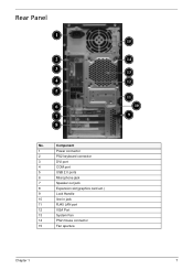
Rear Panel 1 2 3 4 5 6 7 8 No. Component 1 Power connector 2 PS2 keyboard connector 3 DVI port 4 COM port 5 USB 2.0 ports 6 Microphone jack 7 Speaker out jack 8 Expansion slot(graphics card ect.) 9 Lock Handle 10 line-in jack 11 RJ45 LAN port 12 VGA Port 13 System Fan 14 PS2 mouse connector 15 Fan aperture 15 14 13 12 11 10 9 Chapter 1 7
Rear Panel 1 2 3 4 5 6 7 8 No. Component 1 Power connector 2 PS2 keyboard connector 3 DVI port 4 COM port 5 USB 2.0 ports 6 Microphone jack 7 Speaker out jack 8 Expansion slot(graphics card ect.) 9 Lock Handle 10 line-in jack 11 RJ45 LAN port 12 VGA Port 13 System Fan 14 PS2 mouse connector 15 Fan aperture 15 14 13 12 11 10 9 Chapter 1 7
Acer Veriton M430 Desktop Service Guide
Page 15
...Hardware Specifications and Configurations Processor Item Specification Processor Type Support AM3 6-core Thuban CPU (140W) Socket Type AMD Socket AM3 Minimum operating speed 0 MHz (If Stop CPU Clock in Sleep State in BIOS Setup is set to Enabled.) BIOS Item Specification BIOS code programer AMI Kernel with Acer skin BIOS version P01-A0 BIOS ROM type SPI ROM BIOS ROM size 8Mb Support protocol SMBIOS(DMI)2.4/DMI2.0 Device Boot Support Support BBS spec 1st priority: HDD 2nd priority: CD-ROM 3th priority: LAN 4th priority: USB device Support to LS-120 drive YES Support...
...Hardware Specifications and Configurations Processor Item Specification Processor Type Support AM3 6-core Thuban CPU (140W) Socket Type AMD Socket AM3 Minimum operating speed 0 MHz (If Stop CPU Clock in Sleep State in BIOS Setup is set to Enabled.) BIOS Item Specification BIOS code programer AMI Kernel with Acer skin BIOS version P01-A0 BIOS ROM type SPI ROM BIOS ROM size 8Mb Support protocol SMBIOS(DMI)2.4/DMI2.0 Device Boot Support Support BBS spec 1st priority: HDD 2nd priority: CD-ROM 3th priority: LAN 4th priority: USB device Support to LS-120 drive YES Support...
Acer Veriton M430 Desktop Service Guide
Page 16
... Memory Supported 1G~16GB System Memory Item Specification Memory slot number 4 slot Support Memory size per socket 1GB/2GB/4GB Support memory type DDRIII Support memory interface DDRIII 1066/1333MHz Support memory voltage 1.5V Support memory module package 240-pin DDRIII Support to parity check feature Yes Support to error correction code (ECC) feature No Memory module combinations You can install memory modules in any other HDA compatible audio controller. With EAX/Direct Sound 3D/I3DL2/ A3D compatibility, and excellent software utilities...
... Memory Supported 1G~16GB System Memory Item Specification Memory slot number 4 slot Support Memory size per socket 1GB/2GB/4GB Support memory type DDRIII Support memory interface DDRIII 1066/1333MHz Support memory voltage 1.5V Support memory module package 240-pin DDRIII Support to parity check feature Yes Support to error correction code (ECC) feature No Memory module combinations You can install memory modules in any other HDA compatible audio controller. With EAX/Direct Sound 3D/I3DL2/ A3D compatibility, and excellent software utilities...
Acer Veriton M430 Desktop Service Guide
Page 17
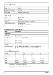
...S3 S4 Power Button V V V USB Keyboard/Mouse V V N/A PME Disabled Disabled Disabled RCT Disabled Disabled Disabled WOR Disabled Disabled Disabled • Devices wake up from S3 should be less than. • Devices wake up from S5 should be less than 10 seconds. SATA Interface Item SATA controller Number of SATA channel Support mode Specification RS880P SATA X 6 RAID/AHCI/IDE mode option USB Port Item Universal HCI USB Class USB Connectors Quantity Specification USB 2.0/1.1 Support legacy keyboard for legacy mode 6 back real ports 4 ports for front daughter board 4 ports...
...S3 S4 Power Button V V V USB Keyboard/Mouse V V N/A PME Disabled Disabled Disabled RCT Disabled Disabled Disabled WOR Disabled Disabled Disabled • Devices wake up from S3 should be less than. • Devices wake up from S5 should be less than 10 seconds. SATA Interface Item SATA controller Number of SATA channel Support mode Specification RS880P SATA X 6 RAID/AHCI/IDE mode option USB Port Item Universal HCI USB Class USB Connectors Quantity Specification USB 2.0/1.1 Support legacy keyboard for legacy mode 6 back real ports 4 ports for front daughter board 4 ports...

Acer Veriton M430 Desktop Service Guide
Page 18
...; CPU asserts STPCLK# and goes into the Stop Grant State. • LED on panel turns amber colour. • Hard disk drive goes into SLEEP mode (for ATA standard interface). • Disable H-sync and V-sync signals to control the VESA DPMS monitor. • Ultra I/O and VGA chip go into power saving mode. • Resume method: Resume to original state by pushing external switch Button,modem ring in,keyboard an mouse for...
...; CPU asserts STPCLK# and goes into the Stop Grant State. • LED on panel turns amber colour. • Hard disk drive goes into SLEEP mode (for ATA standard interface). • Disable H-sync and V-sync signals to control the VESA DPMS monitor. • Ultra I/O and VGA chip go into power saving mode. • Resume method: Resume to original state by pushing external switch Button,modem ring in,keyboard an mouse for...

Acer Veriton M430 Desktop Service Guide
Page 19
... ROM, called CMOS RAM. In this guide display default system values. Chapter 2 12 Before you run the CMOS Setup Utility, make changes to the CMOS setup NOTE: If you are already properly configured and optimized, there is no need to run this guide. Ask a qualified technician for assistance. The system reboots immediately after you have saved all open files. Since most systems are prompted ("Run Setup" message) to the security setup • When a configuration error...
... ROM, called CMOS RAM. In this guide display default system values. Chapter 2 12 Before you run the CMOS Setup Utility, make changes to the CMOS setup NOTE: If you are already properly configured and optimized, there is no need to run this guide. Ask a qualified technician for assistance. The system reboots immediately after you have saved all open files. Since most systems are prompted ("Run Setup" message) to the security setup • When a configuration error...
Acer Veriton M430 Desktop Service Guide
Page 22
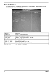
... system. Serial number of the system. Parameter Processor Type Processor Speed System Memory Product Name System Serial Number System BIOS Version BIOS Release Date Asset Tag Number Description Type of the BIOS setup utility. Version number of CPU installed on the system. Speed of system memory installed on the system. Total size of the CPU installed on the system. These entries are for your reference only and are not user-configurable. Date when the BIOS setup utility was released...
... system. Serial number of the system. Parameter Processor Type Processor Speed System Memory Product Name System Serial Number System BIOS Version BIOS Release Date Asset Tag Number Description Type of the BIOS setup utility. Version number of CPU installed on the system. Speed of system memory installed on the system. Total size of the CPU installed on the system. These entries are for your reference only and are not user-configurable. Date when the BIOS setup utility was released...
Acer Veriton M430 Desktop Service Guide
Page 24
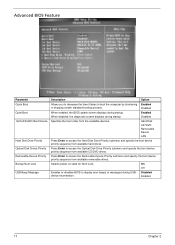
Disabled When enabled, the BIOS splash screen displays during startup. Disabled Enabled 17 Chapter 2 Press Enter to boot the computer by shortening Enabled or skipping certain standard booting process. Advanced BIOS Feature Parameter Quick Boot Quiet Boot 1st/2nd/3rd/4th Boot Device Hard Disk Drive Priority Optical Disk Drives Priority Removable Device Priority Bootup Num-Lock USB Beep Message Description Option Allows you to decrease the time it takes to access the Optical Disk Drive Priority submenu and specify the boot device priority sequence...
Disabled When enabled, the BIOS splash screen displays during startup. Disabled Enabled 17 Chapter 2 Press Enter to boot the computer by shortening Enabled or skipping certain standard booting process. Advanced BIOS Feature Parameter Quick Boot Quiet Boot 1st/2nd/3rd/4th Boot Device Hard Disk Drive Priority Optical Disk Drives Priority Removable Device Priority Bootup Num-Lock USB Beep Message Description Option Allows you to decrease the time it takes to access the Optical Disk Drive Priority submenu and specify the boot device priority sequence...
Acer Veriton M430 Desktop Service Guide
Page 26
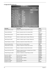
...the onboard graphics Enables or disables the onboard audio controller. Integrated Peripherals Parameter Onboard SATA Controller Onboard SATA Mode Onboard USB Controller Legacy USB Support USB Storage Emulation Onboard Graphics Controller Onboard Graphics Mode Onboard Audio Controller Onboard LAN Controller Onboard LAN Option ROM Onboard Floppy Controller Serial Port1 Address Serial Port1 Mode Serial Port2 Address Serial Port2 Mode Parallel Port Address Parallel Port Mode Description Enables or disables the onboard SATA controller. Select an operating mode for onboard network controller.
...the onboard graphics Enables or disables the onboard audio controller. Integrated Peripherals Parameter Onboard SATA Controller Onboard SATA Mode Onboard USB Controller Legacy USB Support USB Storage Emulation Onboard Graphics Controller Onboard Graphics Mode Onboard Audio Controller Onboard LAN Controller Onboard LAN Option ROM Onboard Floppy Controller Serial Port1 Address Serial Port1 Mode Serial Port2 Address Serial Port2 Mode Parallel Port Address Parallel Port Mode Description Enables or disables the onboard SATA controller. Select an operating mode for onboard network controller.
Acer Veriton M430 Desktop Service Guide
Page 59
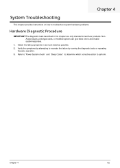
... the symptoms by running the diagnostic tests or repeating thesame operation. 3. Refer to "Power System check" and "Beep Codes" to determine which corrective action to recreate the failure by attempting to perform. Chapter 4 System Troubleshooting This chapter provides instructions on how to troubleshoot system hardware problems. Hardware Diagnostic Procedure IMPORTANT:The diagnostic tests described in as much detail as possible. 2. NonAcerproducts, prototype cards, or modified options can give false...
... the symptoms by running the diagnostic tests or repeating thesame operation. 3. Refer to "Power System check" and "Beep Codes" to determine which corrective action to recreate the failure by attempting to perform. Chapter 4 System Troubleshooting This chapter provides instructions on how to troubleshoot system hardware problems. Hardware Diagnostic Procedure IMPORTANT:The diagnostic tests described in as much detail as possible. 2. NonAcerproducts, prototype cards, or modified options can give false...
Acer Veriton M430 Desktop Service Guide
Page 60
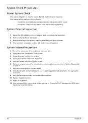
... all peripheral cables from the system. 4. Replace the system covers. 11. Power on a flat, stable surface. 6. Refer to the correct voltage setting. Verify that all the peripherals connected to their appropriate connectors. 9. Place the system unit on the system. 12. If the problem with System Internal Inspection. Make sure that air flow is making contact that components are Acer-qualified and supported. 10...
... all peripheral cables from the system. 4. Replace the system covers. 11. Power on a flat, stable surface. 6. Refer to the correct voltage setting. Verify that all the peripherals connected to their appropriate connectors. 9. Place the system unit on the system. 12. If the problem with System Internal Inspection. Make sure that air flow is making contact that components are Acer-qualified and supported. 10...
Acer Veriton M430 Desktop Service Guide
Page 61
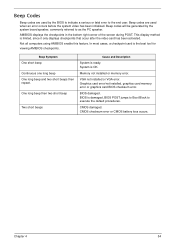
... of the screen during POST. One long beep then two short beep Two short beeps Cause and Description System is the best tool for viewing AMIBIOS checkpoints. BIOS is damaged, BIOS POST jumps to Boot Block to the end user. Graphics card error/not installed, graphics card memory error or graphics card BIOS checksum error. CMOS damaged. Beep codes are used when an error occurs before the system video has been initialized. CMOS checksum error or CMOS battery loss occurs...
... of the screen during POST. One long beep then two short beep Two short beeps Cause and Description System is the best tool for viewing AMIBIOS checkpoints. BIOS is damaged, BIOS POST jumps to Boot Block to the end user. Graphics card error/not installed, graphics card memory error or graphics card BIOS checksum error. CMOS damaged. Beep codes are used when an error occurs before the system video has been initialized. CMOS checksum error or CMOS battery loss occurs...

Acer Veriton M430 Desktop Service Guide
Page 62
... describes the type of checkpoints that flat mode is forced. Serial port is enabled at this point if needed for future use in debugging problems that show the value of the BIOS. If memory sizing module not executed, start memory refresh and do memory sizing in right segments. Re-enable CACHE. Set stack. Copies BIOS from add-in memory. If BIOS recovery is stored in PCI devices. Disable CACHE before system memory is bad...
... describes the type of checkpoints that flat mode is forced. Serial port is enabled at this point if needed for future use in debugging problems that show the value of the BIOS. If memory sizing module not executed, start memory refresh and do memory sizing in right segments. Re-enable CACHE. Set stack. Copies BIOS from add-in memory. If BIOS recovery is stored in PCI devices. Disable CACHE before system memory is bad...

Acer Veriton M430 Desktop Service Guide
Page 64
... the flash part. Make flash write disabled. Restore CPUID value back into register. L1 cache is initialized. Set up floppy controller and data. Read error occurred on system configuration. Recovery file not found flash part size. Disable L1 cache. Check the validity of checkpoints that the found flash part size equals the recovery file size. Enable ATAPI hardware. Bootblock Recovery Code Checkpoints The Bootblock recovery code gets control when the BIOS determines that a BIOS recovery needs to F000 ROM...
... the flash part. Make flash write disabled. Restore CPUID value back into register. L1 cache is initialized. Set up floppy controller and data. Read error occurred on system configuration. Recovery file not found flash part size. Disable L1 cache. Check the validity of checkpoints that the found flash part size equals the recovery file size. Enable ATAPI hardware. Bootblock Recovery Code Checkpoints The Bootblock recovery code gets control when the BIOS determines that a BIOS recovery needs to F000 ROM...
Acer Veriton M430 Desktop Service Guide
Page 68
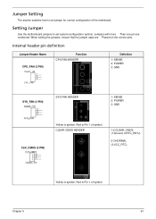
Setting Jumper Use the motherboard jumpers to set system configuration options. Internal header pin definition Jumper/Header Name CPU_FAN (3 PIN) Header_1X3 1 2 3 CPU_FAN Function CPU FAN HEADER Definition 1: SENSE 2: POWER 3: GND SYS_FAN (3 PIN) SYS FAN HEADER 1: SENSE 2: POWER 3: GND CLR_CMOS (3 PIN) Yellow is symbol, Red is Pin 1 of symbol. CLEAR CMOS HEADER 1-2:CLEAR_CMOS (1:Ground, 2:RTC_RSTJ) 2-3:NORMAL (3:VCC_RTC) Yellow is symbol, Red is Pin 1 of symbol. When setting the jumpers, ensure that the jumper caps are numbered. Jumpers with more Than...
Setting Jumper Use the motherboard jumpers to set system configuration options. Internal header pin definition Jumper/Header Name CPU_FAN (3 PIN) Header_1X3 1 2 3 CPU_FAN Function CPU FAN HEADER Definition 1: SENSE 2: POWER 3: GND SYS_FAN (3 PIN) SYS FAN HEADER 1: SENSE 2: POWER 3: GND CLR_CMOS (3 PIN) Yellow is symbol, Red is Pin 1 of symbol. CLEAR CMOS HEADER 1-2:CLEAR_CMOS (1:Ground, 2:RTC_RSTJ) 2-3:NORMAL (3:VCC_RTC) Yellow is symbol, Red is Pin 1 of symbol. When setting the jumpers, ensure that the jumper caps are numbered. Jumpers with more Than...


