Acer Veriton M275 Desktop Series Service Guide
Page 7
... Heat Sink Fan Assembly 31 Removing the Processor 32 Removing the Memory Modules 33 Removing the VGA Card 34 Removing the Hard Disk Drive 35 Removing the Optical Drive 37 Removing the System Fan 39 Removing the Power Supply 40 Removing the OBR and Intrusion Alarm Assembly 41 Removing the Card Reader 43 Removing the Internal Speaker 44 Removing the Mainboard 45 Removing Other Side Panel 47 Removing the Front I/O and USB Assembly 48 Removing the Power Switch and LED Cable Assembly 50 System Troubleshooting 52 Hardware Diagnostic Procedure 52...
... Heat Sink Fan Assembly 31 Removing the Processor 32 Removing the Memory Modules 33 Removing the VGA Card 34 Removing the Hard Disk Drive 35 Removing the Optical Drive 37 Removing the System Fan 39 Removing the Power Supply 40 Removing the OBR and Intrusion Alarm Assembly 41 Removing the Card Reader 43 Removing the Internal Speaker 44 Removing the Mainboard 45 Removing Other Side Panel 47 Removing the Front I/O and USB Assembly 48 Removing the Power Switch and LED Cable Assembly 50 System Troubleshooting 52 Hardware Diagnostic Procedure 52...
Acer Veriton M275 Desktop Series Service Guide
Page 10
...; PCI Express Slot Type: x1 • PCI Express x1 Slot Quantity: 1 • 2 PCI All On-Board Connectors • Rear I/O connectors • 1 D-Sub port • 1COM port (only for commercial vRonnie) • 4 USB ports 2 Chapter 1 Optical disk • Support one SATA 5.25" standard ODD • Support DVD-ROM, DVD-SuperMulti Serial ATA controller • Connector Type: SATA IDE connector. • Connector Quantity: 4 • Storage Type support: • 3.5" SATA/SATAII HDD. • DVD and SuperMulti. • Default AHCI mode in normal BIOS and IDE mode in non-Windows BIOS.
...; PCI Express Slot Type: x1 • PCI Express x1 Slot Quantity: 1 • 2 PCI All On-Board Connectors • Rear I/O connectors • 1 D-Sub port • 1COM port (only for commercial vRonnie) • 4 USB ports 2 Chapter 1 Optical disk • Support one SATA 5.25" standard ODD • Support DVD-ROM, DVD-SuperMulti Serial ATA controller • Connector Type: SATA IDE connector. • Connector Quantity: 4 • Storage Type support: • 3.5" SATA/SATAII HDD. • DVD and SuperMulti. • Default AHCI mode in normal BIOS and IDE mode in non-Windows BIOS.
Acer Veriton M275 Desktop Series Service Guide
Page 11
... Out pin connectors. • One 4 pin CPU Fan connector. • One 24pin ATX interface PS3/PS2 SPS connector. • One 4 pin CPU power connector. • One 2*7 pin front panel IO header. • One Jumper for clear CMOS. • One on board buzzer System BIOS • BIOS Type: AMI with PackedBell skin. • Size:8Mb. Power supply • 300W/250W in stable mode (Acer Assign System Power Unit). • Design for Intel Eaglelake ICH7 series chipset compatible...
... Out pin connectors. • One 4 pin CPU Fan connector. • One 24pin ATX interface PS3/PS2 SPS connector. • One 4 pin CPU power connector. • One 2*7 pin front panel IO header. • One Jumper for clear CMOS. • One on board buzzer System BIOS • BIOS Type: AMI with PackedBell skin. • Size:8Mb. Power supply • 300W/250W in stable mode (Acer Assign System Power Unit). • Design for Intel Eaglelake ICH7 series chipset compatible...

Acer Veriton M275 Desktop Series Service Guide
Page 14
Rear Panel 1 2 3 4 5 6 7 8 16 15 14 13 12 11 10 9 No. Component 1 Power connector 2 PS2 keyboard connector 3 COM port 4 VGA ports 5 USB 2.0 port 6 Microphone/speaker-out/line-in jack 7 Line-out jack 8 Expansion slot(graphics card ect.) 9 Lock Handle 10 Line-in jack 11 COM port 12 Printer port 13 RJ45 LAN port 14 System Fan 15 PS2 mouse connector 16 Fan aperture 6 Chapter 1
Rear Panel 1 2 3 4 5 6 7 8 16 15 14 13 12 11 10 9 No. Component 1 Power connector 2 PS2 keyboard connector 3 COM port 4 VGA ports 5 USB 2.0 port 6 Microphone/speaker-out/line-in jack 7 Line-out jack 8 Expansion slot(graphics card ect.) 9 Lock Handle 10 Line-in jack 11 COM port 12 Printer port 13 RJ45 LAN port 14 System Fan 15 PS2 mouse connector 16 Fan aperture 6 Chapter 1
Acer Veriton M275 Desktop Series Service Guide
Page 15
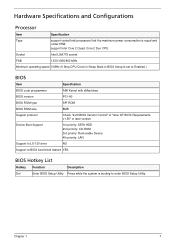
... in Sleep State in BIOS Setup is set to Enabled.) BIOS Item Specification BIOS code programmer AMI Kernel with eMachines BIOS version P01-A0 BIOS ROM type SPI ROM BIOS ROM size 8MB Support protocol Check "2.20 BIOS Version Control" of "Acer DT BIOS Requirements v1.55" or later version Device Boot Support 1st priority: SATA HDD 2nd priority: CD-ROM 3rd priority: Removable Device 4th priority: LAN Support to LS-120 drive NO Support to BIOS boot block feature YES BIOS Hotkey List Hotkey Function Description Del Enter BIOS Setup Utility...
... in Sleep State in BIOS Setup is set to Enabled.) BIOS Item Specification BIOS code programmer AMI Kernel with eMachines BIOS version P01-A0 BIOS ROM type SPI ROM BIOS ROM size 8MB Support protocol Check "2.20 BIOS Version Control" of "Acer DT BIOS Requirements v1.55" or later version Device Boot Support 1st priority: SATA HDD 2nd priority: CD-ROM 3rd priority: Removable Device 4th priority: LAN Support to LS-120 drive NO Support to BIOS boot block feature YES BIOS Hotkey List Hotkey Function Description Del Enter BIOS Setup Utility...
Acer Veriton M275 Desktop Series Service Guide
Page 16
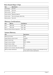
... ICH7 VGA controller Intel G41 Audio controller Realtek ALC662-VC LAN controller Intel ICH7+Realtek LAN 8111DL USB controller Intel ICH7 Memory Combinations Slot Memory Total Memory Slot 1 1GB, 2GB 1GB ~2GB Slot 2 1GB, 2GB 1GB ~2GB Maximum System Memory Supported 1GB ~4GB System Memory Item Specification Memory slot number 2 slot Support Memory size per socket 1GB/2GB Support memory type DDR3 Support memory interface DDR3 1066MHz Support memory voltage 1.5V Support to parity check feature Yes Support to error correction code (ECC) feature No Memory module...
... ICH7 VGA controller Intel G41 Audio controller Realtek ALC662-VC LAN controller Intel ICH7+Realtek LAN 8111DL USB controller Intel ICH7 Memory Combinations Slot Memory Total Memory Slot 1 1GB, 2GB 1GB ~2GB Slot 2 1GB, 2GB 1GB ~2GB Maximum System Memory Supported 1GB ~4GB System Memory Item Specification Memory slot number 2 slot Support Memory size per socket 1GB/2GB Support memory type DDR3 Support memory interface DDR3 1066MHz Support memory voltage 1.5V Support to parity check feature Yes Support to error correction code (ECC) feature No Memory module...
Acer Veriton M275 Desktop Series Service Guide
Page 17
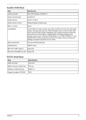
... Audio channel codec 5.1(3port) Audio function control Enable/Disable by BIOS setup Mono or stereo Stereo Compatibility The ALC662-VC series support host audio controller from the Intel ICH series chipset, and also from any other HDA compatible audio controller. Music synthesizer Yes,internal FM synthesizer Sampling rate 192KHz (max) MPU-401 UART support Supported Microphone/Headphone jack Supported SATA Interface Item SATA controller SATA controller resident bus Number of software equalizer and dynamic range control, optional...
... Audio channel codec 5.1(3port) Audio function control Enable/Disable by BIOS setup Mono or stereo Stereo Compatibility The ALC662-VC series support host audio controller from the Intel ICH series chipset, and also from any other HDA compatible audio controller. Music synthesizer Yes,internal FM synthesizer Sampling rate 192KHz (max) MPU-401 UART support Supported Microphone/Headphone jack Supported SATA Interface Item SATA controller SATA controller resident bus Number of software equalizer and dynamic range control, optional...
Acer Veriton M275 Desktop Series Service Guide
Page 18
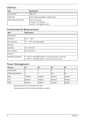
...V V USB Keyboard/Mouse V V N/A PME Disabled Disabled Disabled RCT Disabled Disabled Disabled WOR Disabled Disabled Disabled • Devices wake up from S3 should be less than. • Devices wake up from S5 should be less than 10 second S5 V N/A Disabled Disabled Disabled 10 Chapter 1 On-board: 3 2*5 headers. 4 ports for rear ports. USB Port Item Universal HCI USB Class USB Connectors Quantity Specification USB 2.0/1.1 Support legacy keyboard for legacy mode 2 port for front daughter board. Environmental Requirements Item Specification Temperature Operating...
...V V USB Keyboard/Mouse V V N/A PME Disabled Disabled Disabled RCT Disabled Disabled Disabled WOR Disabled Disabled Disabled • Devices wake up from S3 should be less than. • Devices wake up from S5 should be less than 10 second S5 V N/A Disabled Disabled Disabled 10 Chapter 1 On-board: 3 2*5 headers. 4 ports for rear ports. USB Port Item Universal HCI USB Class USB Connectors Quantity Specification USB 2.0/1.1 Support legacy keyboard for legacy mode 2 port for front daughter board. Environmental Requirements Item Specification Temperature Operating...
Acer Veriton M275 Desktop Series Service Guide
Page 19
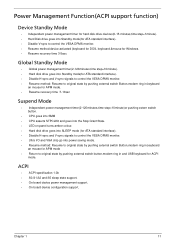
...; CPU asserts STPCLK# and goes into the Stop Grant State. • LED on panel turns amber colour. • Hard disk drive goes into SLEEP mode (for ATA standard interface). • Disable H-sync and V-sync signals to control the VESA DPMS monitor. • Ultra I/O and VGA chip go into power saving mode. • Resume method: Resume to original state by pushing external switch Button,modem ring in,keyboard an mouse for...
...; CPU asserts STPCLK# and goes into the Stop Grant State. • LED on panel turns amber colour. • Hard disk drive goes into SLEEP mode (for ATA standard interface). • Disable H-sync and V-sync signals to control the VESA DPMS monitor. • Ultra I/O and VGA chip go into power saving mode. • Resume method: Resume to original state by pushing external switch Button,modem ring in,keyboard an mouse for...
Acer Veriton M275 Desktop Series Service Guide
Page 20
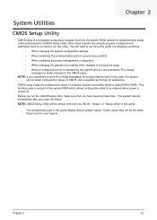
... metaloxide semiconductor (CMOS) Setup Utility. Before you run this guide. This memory area is not part of the system RAM which allows configuration data to be simply referred to run the CMOS Setup Utility, make changes to the CMOS setup NOTE: If you repeatedly receive Run Setup messages, the battery may not be bad. You will be retained when power is turned off. Chapter 2 System Utilities CMOS Setup Utility CMOS setup is a hardware configuration program built into the system ROM, called CMOS RAM.
... metaloxide semiconductor (CMOS) Setup Utility. Before you run this guide. This memory area is not part of the system RAM which allows configuration data to be simply referred to run the CMOS Setup Utility, make changes to the CMOS setup NOTE: If you repeatedly receive Run Setup messages, the battery may not be bad. You will be retained when power is turned off. Chapter 2 System Utilities CMOS Setup Utility CMOS setup is a hardware configuration program built into the system ROM, called CMOS RAM.

Acer Veriton M275 Desktop Series Service Guide
Page 23
... Product Information menu displays basic information about the system. These entries are for your reference only and are not user-configurable. Date when the BIOS setup utility was released Asset tag number of this system. 15 Chapter 2 Product name of CPU installed on the system. Parameter Processor Type Processor Speed System Memory System Manufacturer Product Name System Serial Number System BIOS Version BIOS Release Date Asset Tag Number Description Type of...
... Product Information menu displays basic information about the system. These entries are for your reference only and are not user-configurable. Date when the BIOS setup utility was released Asset tag number of this system. 15 Chapter 2 Product name of CPU installed on the system. Parameter Processor Type Processor Speed System Memory System Manufacturer Product Name System Serial Number System BIOS Version BIOS Release Date Asset Tag Number Description Type of...
Acer Veriton M275 Desktop Series Service Guide
Page 25
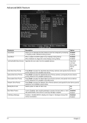
... optical drives. Selects power on state for Num Lock. Disabled Enabled 17 Chapter 2 Press Enter to access the Optical Disk Drive Priority submenu and specify the boot device priority sequence from available removable drives. When disabled, the diagnostic screen displays during startup. Enabled Enables or disables BIOS to appear. Advanced BIOS Feature Parameter Quick Boot Quiet Boot 1st/2nd/3rd/4th Boot Device Hard Disk Drive Priority Optical Disk Drive Priority Removable Drive Priority Network Drive Priority Bootup Num-Lock Boot Write Protect USB Beep Message Description Option...
... optical drives. Selects power on state for Num Lock. Disabled Enabled 17 Chapter 2 Press Enter to access the Optical Disk Drive Priority submenu and specify the boot device priority sequence from available removable drives. When disabled, the diagnostic screen displays during startup. Enabled Enables or disables BIOS to appear. Advanced BIOS Feature Parameter Quick Boot Quiet Boot 1st/2nd/3rd/4th Boot Device Hard Disk Drive Priority Optical Disk Drive Priority Removable Drive Priority Network Drive Priority Bootup Num-Lock Boot Write Protect USB Beep Message Description Option...
Acer Veriton M275 Desktop Series Service Guide
Page 27
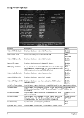
... Controller Onboard SATA Mode Onboard USB Controller Legacy USB Support USB Storage Emulation Onboard Audio Controller Onboard LAN Controller Onboard LAN Option ROM Serial Port1/Port2 Address Serial Port2 Mode Parallel Port Address Parallel Port Mode Parallel Port IRQ ECP Mode DMA Channel Description Option Enables or disables the onboard SATA controller. Enabled Disabled Select an operating mode for legacy USB devices. RAID Native IDE Enables or disables the onboard USB controller. Enabled Disabled Enables or disables the load of embedded option ROM for onboard network controller...
... Controller Onboard SATA Mode Onboard USB Controller Legacy USB Support USB Storage Emulation Onboard Audio Controller Onboard LAN Controller Onboard LAN Option ROM Serial Port1/Port2 Address Serial Port2 Mode Parallel Port Address Parallel Port Mode Parallel Port IRQ ECP Mode DMA Channel Description Option Enables or disables the onboard SATA controller. Enabled Disabled Select an operating mode for legacy USB devices. RAID Native IDE Enables or disables the onboard USB controller. Enabled Disabled Enables or disables the load of embedded option ROM for onboard network controller...
Acer Veriton M275 Desktop Series Service Guide
Page 31
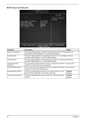
... this option and press to change the HDD password. Enabled Disabled 23 Chapter 2 If not, Not Installed displays. If the password has been installed,Installed displays. This item enables/disables the warning if the case is opened up, and the item below indicatesthe current status of the case. Enabled Disabled This item enables/disables support the boot from USB mass storage devices. This item indicates whether a HDD password has been set . You can use the submenu to access the sub menu...
... this option and press to change the HDD password. Enabled Disabled 23 Chapter 2 If not, Not Installed displays. If the password has been installed,Installed displays. This item enables/disables the warning if the case is opened up, and the item below indicatesthe current status of the case. Enabled Disabled This item enables/disables support the boot from USB mass storage devices. This item indicates whether a HDD password has been set . You can use the submenu to access the sub menu...

Acer Veriton M275 Desktop Series Service Guide
Page 60
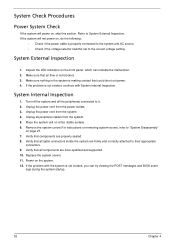
..." and "Beep Codes" to determine which corrective action to recreate the failure by running the diagnostic tests or repeating thesame operation. 3. Obtain the failing symptoms in this chapter are only intended to test Acer products. Chapter 4 52 Non-Acer products, prototype cards, or modified options can give false errors and invalid system responses. 1. Chapter 4 System Troubleshooting This chapter provides instructions on how to troubleshoot system hardware problems. Hardware Diagnostic Procedure...
..." and "Beep Codes" to determine which corrective action to recreate the failure by running the diagnostic tests or repeating thesame operation. 3. Obtain the failing symptoms in this chapter are only intended to test Acer products. Chapter 4 52 Non-Acer products, prototype cards, or modified options can give false errors and invalid system responses. 1. Chapter 4 System Troubleshooting This chapter provides instructions on how to troubleshoot system hardware problems. Hardware Diagnostic Procedure...
Acer Veriton M275 Desktop Series Service Guide
Page 61
... all the peripherals connected to System External Inspection. Verify that components are Acer-qualified and supported. 10. Replace the system covers. 11. Power on a flat, stable surface. 6. If the problem with System Internal Inspection. If the problem is making contact that air flow is properly connected to the system and AC source. • Check if the voltage selector switchis set to the correct...
... all the peripherals connected to System External Inspection. Verify that components are Acer-qualified and supported. 10. Replace the system covers. 11. Power on a flat, stable surface. 6. If the problem with System Internal Inspection. If the problem is making contact that air flow is properly connected to the system and AC source. • Check if the voltage selector switchis set to the correct...
Acer Veriton M275 Desktop Series Service Guide
Page 62
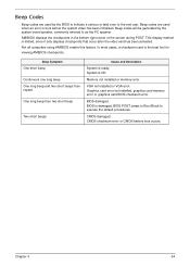
... is damaged, BIOS POST jumps to Boot Block to execute the default procedures. BIOS is ready. Memory not installed or memory error. Beep codes will be generated by the BIOS to indicate a serious or fatal error to the end user. CMOS checksum error or CMOS battery loss occurs. Graphics card error/not installed, graphics card memory error or graphics card BIOS checksum error. Beep codes are used when an error occurs before the system video has been initialized. Beep Codes Beep codes are used by the system board speaker, commonly referred...
... is damaged, BIOS POST jumps to Boot Block to execute the default procedures. BIOS is ready. Memory not installed or memory error. Beep codes will be generated by the BIOS to indicate a serious or fatal error to the end user. CMOS checksum error or CMOS battery loss occurs. Graphics card error/not installed, graphics card memory error or graphics card BIOS checksum error. Beep codes are used when an error occurs before the system video has been initialized. Beep Codes Beep codes are used by the system board speaker, commonly referred...
Acer Veriton M275 Desktop Series Service Guide
Page 63
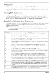
... document for future use in PCI devices. Disable CACHE before system memory is tested. Restore CPUID value back into memory. Leaves all checkpoints generated by the BIOS requires acheckpoint card, also referred to determine if BIOSrecovery is done includingRTC and keyboard controller. Re-enable CACHE. Do additional chipsetinitialization. Both key sequence and OEM specific method is checked to as a POST card or POST diagnostic card. Verify the bootblock...
... document for future use in PCI devices. Disable CACHE before system memory is tested. Restore CPUID value back into memory. Leaves all checkpoints generated by the BIOS requires acheckpoint card, also referred to determine if BIOSrecovery is done includingRTC and keyboard controller. Re-enable CACHE. Do additional chipsetinitialization. Both key sequence and OEM specific method is checked to as a POST card or POST diagnostic card. Verify the bootblock...

Acer Veriton M275 Desktop Series Service Guide
Page 64
... OEM specific method. Disable ATAPI hardware. Set up floppy controller and data. Enable ATAPI hardware. Search for pre-defined recovery file name in PCI devices. Recovery file not found flash part size. Check the validity of the recovery file configuration to vendor requirements, system chipset or option ROMs from floppy. Checkpoints maychange due to the current configuration of the BIOS. DMA controller is initialized. 8259 interrupt controller is enabled. Start reading the recovery file...
... OEM specific method. Disable ATAPI hardware. Set up floppy controller and data. Enable ATAPI hardware. Search for pre-defined recovery file name in PCI devices. Recovery file not found flash part size. Check the validity of the recovery file configuration to vendor requirements, system chipset or option ROMs from floppy. Checkpoints maychange due to the current configuration of the BIOS. DMA controller is initialized. 8259 interrupt controller is enabled. Start reading the recovery file...

Acer Veriton M275 Desktop Series Service Guide
Page 68
... CPU FAN HEADER 1: GND 2: POWER 3: SENSE 4: CONTROL 60 Jumpers with more Than one pin, the jumper is OPEN. Use the motherboard jumpers to set jumper for correct configuration of the mainboard. Jumpers withmore than one pin are SHORT. The illustrations show a 2-pin jumper.When the jumper cap is SHORT. Jumper CLR_CMOS1 Type Description 3-pin Clear CMOS Setting (default) 1-2: NORMAL 2-3: CLEAR Before clearing theCMOS, make sure toturn off the system. This illustration shows a 3-pin jumper.Pins 1 and 2 are numbered. When setting the jumpers, ensure that the jumper...
... CPU FAN HEADER 1: GND 2: POWER 3: SENSE 4: CONTROL 60 Jumpers with more Than one pin, the jumper is OPEN. Use the motherboard jumpers to set jumper for correct configuration of the mainboard. Jumpers withmore than one pin are SHORT. The illustrations show a 2-pin jumper.When the jumper cap is SHORT. Jumper CLR_CMOS1 Type Description 3-pin Clear CMOS Setting (default) 1-2: NORMAL 2-3: CLEAR Before clearing theCMOS, make sure toturn off the system. This illustration shows a 3-pin jumper.Pins 1 and 2 are numbered. When setting the jumpers, ensure that the jumper...


