
Veriton 5500/7500 Service Guide
Page 8
... Module 95 Removing Power Switch Cable 96 Removing the System Main Board 97 Removing the I/O Port Bracket 97 Veriton 7500/ 7500G Disassembly Procedure Flowchart 98 Disassembling the Veriton 7500/ 7500G 99 Opening the Housing 99 Removing the Front Panel 99 Removing the Modem Card 100 Removing the AGP... 104 Removing the Intrusion Alarm Cable Module 104 Removing a DIMM 105 Removing the CPU Fan Sink 105 Removing and Installing the Processor 106 Removing and Installing the RTC Battery 106 Removing the Power Supply 107 Removing the LED Activity Indicators With Power Switch Cable Module...
... Module 95 Removing Power Switch Cable 96 Removing the System Main Board 97 Removing the I/O Port Bracket 97 Veriton 7500/ 7500G Disassembly Procedure Flowchart 98 Disassembling the Veriton 7500/ 7500G 99 Opening the Housing 99 Removing the Front Panel 99 Removing the Modem Card 100 Removing the AGP... 104 Removing the Intrusion Alarm Cable Module 104 Removing a DIMM 105 Removing the CPU Fan Sink 105 Removing and Installing the Processor 106 Removing and Installing the RTC Battery 106 Removing the Power Supply 107 Removing the LED Activity Indicators With Power Switch Cable Module...
Veriton 5500/7500 Service Guide
Page 10
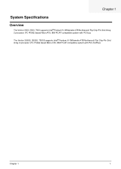
Chapter 1 System Specifications Overview The Veriton 3500, 5500, 7500 supports Intel® Pentium IV (Willamette 478/Northwood) Flip Chip-Pin Grid Array 2 processor (FC-PGA2) based Micro ATX, IBM PC/AT compatible system with PCI/ AGPbus. Chapter 1 1 The Veriton 3500G, 5500G, 7500G supports Intel® Pentium IV (Willamette 478/Northwood) Flip Chip-Pin Grid Array 2 processor (FC-PGA2) based Micro ATX, IBM PC/AT compatible system with PCI bus.
Chapter 1 System Specifications Overview The Veriton 3500, 5500, 7500 supports Intel® Pentium IV (Willamette 478/Northwood) Flip Chip-Pin Grid Array 2 processor (FC-PGA2) based Micro ATX, IBM PC/AT compatible system with PCI/ AGPbus. Chapter 1 1 The Veriton 3500G, 5500G, 7500G supports Intel® Pentium IV (Willamette 478/Northwood) Flip Chip-Pin Grid Array 2 processor (FC-PGA2) based Micro ATX, IBM PC/AT compatible system with PCI bus.
Veriton 5500/7500 Service Guide
Page 11
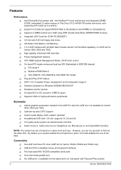
... ! On-board PCI master enhanced local bus IDE (Embedded in the AGP Pro card slot (AGP slot: not available for Veriton 3500, 5500 and 7500) ! Supports USB 2.0 high-performance peripherals Multimedia ! 128-bit graphics accelerator installed in 82801DB chipset). ! Liquid crystal display (LCD... V AGP interface with supporting CPU clock up to -DC converter (VRM 9.0 spec) ! Intel Pentium® IV processor with Plug and Play function 2 Veriton 3500/5500/7500 Hardware monitor function ! CPU SMM (System Management Mode), STOP clock control ! Features Performance ! One AGP and three ...
... ! On-board PCI master enhanced local bus IDE (Embedded in the AGP Pro card slot (AGP slot: not available for Veriton 3500, 5500 and 7500) ! Supports USB 2.0 high-performance peripherals Multimedia ! 128-bit graphics accelerator installed in 82801DB chipset). ! Liquid crystal display (LCD... V AGP interface with supporting CPU clock up to -DC converter (VRM 9.0 spec) ! Intel Pentium® IV processor with Plug and Play function 2 Veriton 3500/5500/7500 Hardware monitor function ! CPU SMM (System Management Mode), STOP clock control ! Features Performance ! One AGP and three ...
Veriton 5500/7500 Service Guide
Page 25
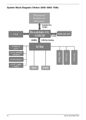
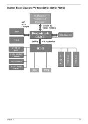
System Block Diagram (Veriton 3500/ 5500/ 7500) VGA 6 USB 2.0 ports 2 ATA 100 IDE Channels LAN Connect AC97' Audio CODEC Willamette/ Northwood Processor Scaleable Bus 3.2GB/s Brookdale-GL GMCH 2.12GB/s DDDDRR-2-26666/ /220000 266MB/s 8-Bit Hub Interface ICH4 SIO FWH PCI Slot PCI Slot PCI Slot 16 Veriton 3500/5500/7500
System Block Diagram (Veriton 3500/ 5500/ 7500) VGA 6 USB 2.0 ports 2 ATA 100 IDE Channels LAN Connect AC97' Audio CODEC Willamette/ Northwood Processor Scaleable Bus 3.2GB/s Brookdale-GL GMCH 2.12GB/s DDDDRR-2-26666/ /220000 266MB/s 8-Bit Hub Interface ICH4 SIO FWH PCI Slot PCI Slot PCI Slot 16 Veriton 3500/5500/7500
Veriton 5500/7500 Service Guide
Page 26
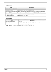
System Block Diagram (Veriton 3500G/ 5500G/ 7500G) AGP VGA AGP 4X/ 2X 1.5V signal Willamette/ Northwood Processor Scaleable Bus 3.2GB/s (4.25GB/s) Brookdale-G GMCH DDDDRR-2-26666/ /220000 2.12GB/s 266MB/s 8-Bit Hub Interface 6 USB 2.0 ports 2 ATA 100 IDE Channels LAN Connect AC97' Audio CODEC ICH4 SIO FWH PCI Slot PCI Slot PCI Slot Chapter 1 17
System Block Diagram (Veriton 3500G/ 5500G/ 7500G) AGP VGA AGP 4X/ 2X 1.5V signal Willamette/ Northwood Processor Scaleable Bus 3.2GB/s (4.25GB/s) Brookdale-G GMCH DDDDRR-2-26666/ /220000 2.12GB/s 266MB/s 8-Bit Hub Interface 6 USB 2.0 ports 2 ATA 100 IDE Channels LAN Connect AC97' Audio CODEC ICH4 SIO FWH PCI Slot PCI Slot PCI Slot Chapter 1 17

Veriton 5500/7500 Service Guide
Page 32
... Slot Speed Item Minimum operating speed Voltage Specification Intel® Pentium IV FC-PGA2 processors with mPGA478 package Socket mPGA478 Internal: 1.4~2.4GHz+ External: 400/533MHz Data Bus Frequency for Brookdale-G and 400 MHz for Brookdale-GL. 0 MHz (If Stop CPU ... Yes NOTE: The BIOS can be overwritten/upgraded using the FLASH utility (AWDFLASH.EXE). Press in Sleep State the BIOS Setup is booting to Enabled.) Processor voltage can be detected by the system without setting any jumper.
... Slot Speed Item Minimum operating speed Voltage Specification Intel® Pentium IV FC-PGA2 processors with mPGA478 package Socket mPGA478 Internal: 1.4~2.4GHz+ External: 400/533MHz Data Bus Frequency for Brookdale-G and 400 MHz for Brookdale-GL. 0 MHz (If Stop CPU ... Yes NOTE: The BIOS can be overwritten/upgraded using the FLASH utility (AWDFLASH.EXE). Press in Sleep State the BIOS Setup is booting to Enabled.) Processor voltage can be detected by the system without setting any jumper.
Veriton 5500/7500 Service Guide
Page 34
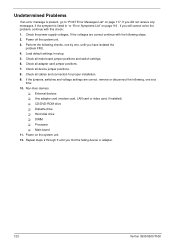
L2 Cache RAM size Pentium IV processor: 512 KB for Northwood and 256KB for Veriton 3500/ 5500/ 7500 doesn't have AGP VGA slot. Chapter 1 25 Cache Memory Item Specification First-Level Cache Configurations Cache function control Enable/Disable by BIOS Setup (Advanced options) ...
L2 Cache RAM size Pentium IV processor: 512 KB for Northwood and 256KB for Veriton 3500/ 5500/ 7500 doesn't have AGP VGA slot. Chapter 1 25 Cache Memory Item Specification First-Level Cache Configurations Cache function control Enable/Disable by BIOS Setup (Advanced options) ...

Veriton 5500/7500 Service Guide
Page 63
Indicates the processor speed. 55 Veriton 3500/5500/7500 Parameter Processor Processor Spee Description Indicates the type of processor installed in this menu. Frequency Control The following table describes the parameters found in your computer.
Indicates the processor speed. 55 Veriton 3500/5500/7500 Parameter Processor Processor Spee Description Indicates the type of processor installed in this menu. Frequency Control The following table describes the parameters found in your computer.

Veriton 5500/7500 Service Guide
Page 91
... with any metal or with the one on the socket. See "Removing the CPU Fan Sink" on the processor should align with your hands. Removing and Installing the Processor 1. 4. Before putting back the processor back to its correct position, please note that the side with the triangle mark on page 82 Pull the... sink from the socket. 4. See "Removing the FDD and DVD Frame" on page 73 2. See "Removing the Housing Cover" on page 75" 3. After putting the processor back to the socket, put the levers back to scure the processor. . 83 Veriton 3500/5500/7500
... with any metal or with the one on the socket. See "Removing the CPU Fan Sink" on the processor should align with your hands. Removing and Installing the Processor 1. 4. Before putting back the processor back to its correct position, please note that the side with the triangle mark on page 82 Pull the... sink from the socket. 4. See "Removing the FDD and DVD Frame" on page 73 2. See "Removing the Housing Cover" on page 75" 3. After putting the processor back to the socket, put the levers back to scure the processor. . 83 Veriton 3500/5500/7500

Veriton 5500/7500 Service Guide
Page 98
See "Removing a Dummy Link Bar" on page 86 2. Detach the fan/heatsink cable connector and release the two CPU fan sink levers from the CPU fan sink socket carefully, and then lift the fan/heatsink from the processor. 4. Press down the levers back to their original position . Never touch the heatsink with any metal or with your hands. Chapter 3 90 See "Removing the Housing Cover" on page 87 3. WARNING:The heatsink becomes very hot when the system is On. Removing the CPU Fan Sink 1.
See "Removing a Dummy Link Bar" on page 86 2. Detach the fan/heatsink cable connector and release the two CPU fan sink levers from the CPU fan sink socket carefully, and then lift the fan/heatsink from the processor. 4. Press down the levers back to their original position . Never touch the heatsink with any metal or with your hands. Chapter 3 90 See "Removing the Housing Cover" on page 87 3. WARNING:The heatsink becomes very hot when the system is On. Removing the CPU Fan Sink 1.

Veriton 5500/7500 Service Guide
Page 99
..., put it back and press it into the correct position to scure the processor. . See "Removing the Housing Cover" on page 86 2. Before putting back the processor back to its original position to secure it well .. 91 Veriton 3500/5500/7500 See "Removing the Housing Cover" on page 86 2. See "Removing a Dummy Link Bar... 3. Press the latch to release the RTC battery, lift up to its correct position, please note that the side with the triangle mark on the processor should align with the one on the socket. To install the RTC battery, put the socket lever back to release the...
..., put it back and press it into the correct position to scure the processor. . See "Removing the Housing Cover" on page 86 2. Before putting back the processor back to its original position to secure it well .. 91 Veriton 3500/5500/7500 See "Removing the Housing Cover" on page 86 2. See "Removing a Dummy Link Bar... 3. Press the latch to release the RTC battery, lift up to its correct position, please note that the side with the triangle mark on the processor should align with the one on the socket. To install the RTC battery, put the socket lever back to release the...

Veriton 5500/7500 Service Guide
Page 113
Never touch the heatsink with any metal or with your hands. 105 Veriton 3500/5500/7500 WARNING:The heatsink becomes very hot when the system is On. Removing a DIMM 1. Removing the CPU Fan Sink 1. Press the levers on both sides of ... cable connector and release the two CPU fan sink levers from the CPU fan sink socket carefully, and then lift the fan/heatsink from the processor . 3. Press down the levers back to remove it .
Never touch the heatsink with any metal or with your hands. 105 Veriton 3500/5500/7500 WARNING:The heatsink becomes very hot when the system is On. Removing a DIMM 1. Removing the CPU Fan Sink 1. Press the levers on both sides of ... cable connector and release the two CPU fan sink levers from the CPU fan sink socket carefully, and then lift the fan/heatsink from the processor . 3. Press down the levers back to remove it .

Veriton 5500/7500 Service Guide
Page 114
... "Removing the Housing" on page 99. (Remove the left panel only) 2. Chapter 3 106 After putting the processor back to the socket, put it back and press it well. . Press the latch to lying position with the one on page 105. 3. See "Removing ... page 99. (Remove the left panel only) 2. To install the RTC battery, put the socket lever back to release the processor pins from the socket holes an pull out the processor from the socket.. 4. Put the housing to release the RTC battery, lift up to its correct position, please note that the...
... "Removing the Housing" on page 99. (Remove the left panel only) 2. Chapter 3 106 After putting the processor back to the socket, put it back and press it well. . Press the latch to lying position with the one on page 105. 3. See "Removing ... page 99. (Remove the left panel only) 2. To install the RTC battery, put the socket lever back to release the processor pins from the socket holes an pull out the processor from the socket.. 4. Put the housing to release the RTC battery, lift up to its correct position, please note that the...

Veriton 5500/7500 Service Guide
Page 119
... BIOS common tasks carried out by an unique check point number. For other unique check point numbers that are not listed in numeric co-processor and cache memory subsystem ! Microprocessor with battery backup ! Interrupt system (8259 module) ! Power-On Self-Test (POST) Each time you...part transparent to E000 & F000 shadow RAM. If POST discovers errors in physical address 1000:0 Reserved Initial Superio_Early _Init switch 111 Veriton 3500/5500/7500 The main components on the main board that boots the system, initializes and diagnoses the system components, and controls the operation ...
... BIOS common tasks carried out by an unique check point number. For other unique check point numbers that are not listed in numeric co-processor and cache memory subsystem ! Microprocessor with battery backup ! Interrupt system (8259 module) ! Power-On Self-Test (POST) Each time you...part transparent to E000 & F000 shadow RAM. If POST discovers errors in physical address 1000:0 Reserved Initial Superio_Early _Init switch 111 Veriton 3500/5500/7500 The main components on the main board that boots the system, initializes and diagnoses the system components, and controls the operation ...

Veriton 5500/7500 Service Guide
Page 122
... logo 2. Reserved Initialize USB Reserved Test all memory (clear all extended memory to enter Setup utility; Reserved Reserved Okay to 0) Reserved Reserved Display number of processors (multi-processor platform) Reserved 1. not until this POST stage can users enter the CMOS setup utility Reserved Reserved Reserved Reserved Initialize PS/2 Mouse Reserved Chapter 4 114...
... logo 2. Reserved Initialize USB Reserved Test all memory (clear all extended memory to enter Setup utility; Reserved Reserved Okay to 0) Reserved Reserved Display number of processors (multi-processor platform) Reserved 1. not until this POST stage can users enter the CMOS setup utility Reserved Reserved Reserved Reserved Initialize PS/2 Mouse Reserved Chapter 4 114...

Veriton 5500/7500 Service Guide
Page 123
...size information for full screen logo 3. Auto assign ports to "AUTO" Reserved 1. Reserved Detect serial ports & parallel ports Reserved Reserved Detect & install co-processor Reserved Reserved Reserved Reserved 1. Reserved Reserved 1. Set up floppy related fields in stack back to all ISA PnP devices. 2. If password is set , ... no errors occur or F1 key is pressed Reserved Detect & install all data in 40: hardware. . Initialize ISA PnP boot devices. 115 Veriton 3500/5500/7500 Save all IDE devices: HDD, LS120, ZIP,CDROM..... Reserved 1. Initialize floppy controller 2.
...size information for full screen logo 3. Auto assign ports to "AUTO" Reserved 1. Reserved Detect serial ports & parallel ports Reserved Reserved Detect & install co-processor Reserved Reserved Reserved Reserved 1. Reserved Reserved 1. Set up floppy related fields in stack back to all ISA PnP devices. 2. If password is set , ... no errors occur or F1 key is pressed Reserved Detect & install all data in 40: hardware. . Initialize ISA PnP boot devices. 115 Veriton 3500/5500/7500 Save all IDE devices: HDD, LS120, ZIP,CDROM..... Reserved 1. Initialize floppy controller 2.

Veriton 5500/7500 Service Guide
Page 127
... BIOS Setup. 2. Diskette drive 5. Error Symptom Action/FRU Processor / Processor Fan NOTE: Normally, the processor fan should be operative, and the processor clock setting should be +12Vdc. Processor 2. In Windows Systems, check settings in the left column. Diskette drive connection/cable 4. Main board. 119 Veriton 3500/5500/7500 Error Symptoms List NOTE: To diagnose a problem, first find...
... BIOS Setup. 2. Diskette drive 5. Error Symptom Action/FRU Processor / Processor Fan NOTE: Normally, the processor fan should be operative, and the processor clock setting should be +12Vdc. Processor 2. In Windows Systems, check settings in the left column. Diskette drive connection/cable 4. Main board. 119 Veriton 3500/5500/7500 Error Symptoms List NOTE: To diagnose a problem, first find...
Veriton 5500/7500 Service Guide
Page 131
...6. If the jumpers, switches and voltage settings are correct continue with this check: 1. Non-Acer devices ! External devices ! CD/DVD-ROM drive ! DIMM ! Power on page 117. If...on the system unit. 12. Check the power supply voltages. Check all device jumper positions. 8. Processor ! Power off the system unit. 3. Perform the following steps: 2. Load default settings in "... 9. Repeat steps 2 through 5 until you find the failing device or adapter. 123 Veriton 3500/5500/7500 Hard disk drive ! If you still cannot solve the problem, continue with the following checks...
...6. If the jumpers, switches and voltage settings are correct continue with this check: 1. Non-Acer devices ! External devices ! CD/DVD-ROM drive ! DIMM ! Power on page 117. If...on the system unit. 12. Check the power supply voltages. Check all device jumper positions. 8. Processor ! Power off the system unit. 3. Perform the following steps: 2. Load default settings in "... 9. Repeat steps 2 through 5 until you find the failing device or adapter. 123 Veriton 3500/5500/7500 Hard disk drive ! If you still cannot solve the problem, continue with the following checks...
Veriton 5500/7500 Service Guide
Page 155
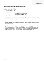
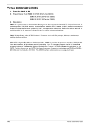
... but also a real time to market product for the INTEL Pentium 4 processor and INTEL Northwood processor. Project Name/ Code: S88M / 91.31V01.301(Veriton 3500) S88M/ 91.31V01.201(Veriton 5500) S88M/ 91.31V01.101(Veriton 7500) 3. S88M /GL Main Board, using INTEL Pentium 4 Processor in the PC market, S88M/GL stands for not only the image...
... but also a real time to market product for the INTEL Pentium 4 processor and INTEL Northwood processor. Project Name/ Code: S88M / 91.31V01.301(Veriton 3500) S88M/ 91.31V01.201(Veriton 5500) S88M/ 91.31V01.101(Veriton 7500) 3. S88M /GL Main Board, using INTEL Pentium 4 Processor in the PC market, S88M/GL stands for not only the image...
Veriton 5500/7500 Service Guide
Page 156
...As a technology leader in the 478 Pin package, delivers a mainstream desktop platform solution. The CPU interface supports the INTEL Pentium 4 processor subset of the Extended Mode of the best performance product for Intel's next generation mainstream platform but also a real time to market ...200 MHz and front side bus 400/ 533. Project Name/ Code: S88M 91.31V01.301(Veriton 3500G) S88M 91.31V01.201(Veriton 5500G) S88M 91.31V01.101(Veriton 7500G) 3. The GMCH contains advanced power management logic. 148 Veriton 3500/5500/7500 Veriton 3500G/5500G/7500G 1. Brand No: S88M/ G MB 2.
...As a technology leader in the 478 Pin package, delivers a mainstream desktop platform solution. The CPU interface supports the INTEL Pentium 4 processor subset of the Extended Mode of the best performance product for Intel's next generation mainstream platform but also a real time to market ...200 MHz and front side bus 400/ 533. Project Name/ Code: S88M 91.31V01.301(Veriton 3500G) S88M 91.31V01.201(Veriton 5500G) S88M 91.31V01.101(Veriton 7500G) 3. The GMCH contains advanced power management logic. 148 Veriton 3500/5500/7500 Veriton 3500G/5500G/7500G 1. Brand No: S88M/ G MB 2.


