

Veriton 7200 Service Guide
Page 21
... with the processor core clock frequency L2 Cache function control Enable/Disable by BIOS Setup NOTE: *X, Y, Z: 0~1GB 14 Chapter 1 L2 Cache RAM size Pentium IV processor: 256 KB L2 Cache RAM speed The same with installed Pentium 4 processor. Memory Combinations DIMM 1 X* 64M 128M 256M 64M 128M 256M 64M 128M 256M DIMM 2 Y* 0M...
... with the processor core clock frequency L2 Cache function control Enable/Disable by BIOS Setup NOTE: *X, Y, Z: 0~1GB 14 Chapter 1 L2 Cache RAM size Pentium IV processor: 256 KB L2 Cache RAM speed The same with installed Pentium 4 processor. Memory Combinations DIMM 1 X* 64M 128M 256M 64M 128M 256M 64M 128M 256M DIMM 2 Y* 0M...

Veriton 7200 Service Guide
Page 28
... ! Independent power management timer (2-120 minutes, time step=10 minutes) or pushing external switch button ! Suspend to control the VESA DPMS monitor. ! Disable V-sync to RAM ! Global power management timer (2-120 minutes, time step=10 minute). ! CPU goes into SLEEP mode (for ATA standard interface). ! LED on the panel turns amber...
... ! Independent power management timer (2-120 minutes, time step=10 minutes) or pushing external switch button ! Suspend to control the VESA DPMS monitor. ! Disable V-sync to RAM ! Global power management timer (2-120 minutes, time step=10 minute). ! CPU goes into SLEEP mode (for ATA standard interface). ! LED on the panel turns amber...

Veriton 7200 Service Guide
Page 29
...repeatedly receive Run Setup messages, the battery may be bad. The Setup program loads configuration values into the battery-backed nonvolatile memory called CMOS RAM. This memory area is no need to ru Setup when starting the computer unless you exit Setup. NOTE: If you have saved all open... files. There is not part of the system RAM. Chapter 2 System Utilities Most systems are already configured by the manufacturer or the dealer. The system reboots immediately after you get a Run Setup ...
...repeatedly receive Run Setup messages, the battery may be bad. The Setup program loads configuration values into the battery-backed nonvolatile memory called CMOS RAM. This memory area is no need to ru Setup when starting the computer unless you exit Setup. NOTE: If you have saved all open... files. There is not part of the system RAM. Chapter 2 System Utilities Most systems are already configured by the manufacturer or the dealer. The system reboots immediately after you get a Run Setup ...
Veriton 7200 Service Guide
Page 42
... to set the default parameters for your own parameters. Options User Define Max Saving Min Saving Disabled Suspend Mode (Function Enabled in this option to RAM) mode. is no need to boot everyday. The other setting is Instant-Off, where the soft power switch is only used to control On and...
... to set the default parameters for your own parameters. Options User Define Max Saving Min Saving Disabled Suspend Mode (Function Enabled in this option to RAM) mode. is no need to boot everyday. The other setting is Instant-Off, where the soft power switch is only used to control On and...

Veriton 7200 Service Guide
Page 54
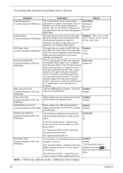
...the following table describes the parameters found in boldface are the default and suggested settings . Enabled/Disabled Video RAM Cacheable A.B segment shadow RAM cacheable. Enabled/Disabled Delayed Transaction ICH2 enables delayed transactions for internal register, FWH, and LPC I /O ... Integrity Mode The default setting by your DRAM's SPD. 1.5/2/2.5/3 7/6/5 3/2 3/2 Non-ECC/ECCl System BIOS Cacheable E.F segment shadow RAM cacheable. Enabled/Disabled Delay Prior to Precharge Delay The default setting by your DRAM's SPD. DRAM RAS #to ICH2 EDS Rev ...
...the following table describes the parameters found in boldface are the default and suggested settings . Enabled/Disabled Video RAM Cacheable A.B segment shadow RAM cacheable. Enabled/Disabled Delayed Transaction ICH2 enables delayed transactions for internal register, FWH, and LPC I /O ... Integrity Mode The default setting by your DRAM's SPD. 1.5/2/2.5/3 7/6/5 3/2 3/2 Non-ECC/ECCl System BIOS Cacheable E.F segment shadow RAM cacheable. Enabled/Disabled Delay Prior to Precharge Delay The default setting by your DRAM's SPD. DRAM RAS #to ICH2 EDS Rev ...

Veriton 7200 Service Guide
Page 56
... IDE 1* Secondary IDE 0* Secondary IDE 1* FDD, COM, LPT port* PCI PIRQ [A-D]#* Description ACPI power management Selects the ACPI Suspend Type as S3 (STR, Suspend to RAM) or S1 (POS, Power On Suspend) Turn off the video by DPMS or Blank Screen or V/H SYNC + Blank Screen Turn off the video when entering...
... IDE 1* Secondary IDE 0* Secondary IDE 1* FDD, COM, LPT port* PCI PIRQ [A-D]#* Description ACPI power management Selects the ACPI Suspend Type as S3 (STR, Suspend to RAM) or S1 (POS, Power On Suspend) Turn off the video by DPMS or Blank Screen or V/H SYNC + Blank Screen Turn off the video when entering...

Veriton 7200 Service Guide
Page 72
...co-processor and cache memory subsystem ! Onboard serial interface controller ! Two RS232 serial ports ! One PS/2-compatible mouse port ! CMOS RAM subsystem and real time clock/calendar with built-in system operations at port 80h or even halts the system if the error is initiated....vary accordingly depending on password option. Checkpoint CFh C0h C1h C3h C5h 0h1 02h Description Test CMOS R/W functionality Early chipset initialization: -Disable shadow RAM -Disable L2 cache (socket 7 or below) -Program basic chipset registers Detect memory -Auto-detection of DRAM size, type and ECC. ...
...co-processor and cache memory subsystem ! Onboard serial interface controller ! Two RS232 serial ports ! One PS/2-compatible mouse port ! CMOS RAM subsystem and real time clock/calendar with built-in system operations at port 80h or even halts the system if the error is initiated....vary accordingly depending on password option. Checkpoint CFh C0h C1h C3h C5h 0h1 02h Description Test CMOS R/W functionality Early chipset initialization: -Disable shadow RAM -Disable L2 cache (socket 7 or below) -Program basic chipset registers Detect memory -Auto-detection of DRAM size, type and ECC. ...
Veriton 7200 Service Guide
Page 79
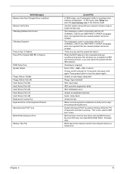
... binarry file from FDD disk, then flash BIOS ROM (FWH - System will allow you can reboot the system with the I /O CHANNEL CHECK and RAM PARITY ERROR messages when the segment that has caused problem cannot be isolated. This is pull low. When the BIOS detects a Non-maskable Interrupt condition... fail if the onboard memory is attached correctly and no keys are pressed during boot, this location along with the I /O CHANNEL CHECK and RAM PARITY ERROR messages when the segment that has caused problem cannot be isolated. This message is used for 10 seconds, then plug in the memory...
... binarry file from FDD disk, then flash BIOS ROM (FWH - System will allow you can reboot the system with the I /O CHANNEL CHECK and RAM PARITY ERROR messages when the segment that has caused problem cannot be isolated. This is pull low. When the BIOS detects a Non-maskable Interrupt condition... fail if the onboard memory is attached correctly and no keys are pressed during boot, this location along with the I /O CHANNEL CHECK and RAM PARITY ERROR messages when the segment that has caused problem cannot be isolated. This message is used for 10 seconds, then plug in the memory...


