
TravelMate 4150 / 4650 Service Guide
Page 7
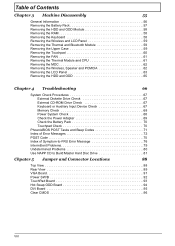
Table of Contents Chapter 3 Machine Disassembly 55 General Information 56 Removing the Battery Pack 57 Removing the HDD and ODD Module 58 Removing the RAM 58 Removing the Keyboard 58 Removing the Wireless and LCD Panel 59 Removing ...-ROM Drive Check 67 Keyboard or Auxiliary Input Device Check 67 Memory Check 68 Power System Check 68 Check the Power Adapter 69 Check the Battery Pack 70 Touchpad Check 70 PhoenixBIOS POST Tasks and Beep Codes 71 Index of Error Messages 72 POST Code 75 Index of Symptom-to-FRU...
Table of Contents Chapter 3 Machine Disassembly 55 General Information 56 Removing the Battery Pack 57 Removing the HDD and ODD Module 58 Removing the RAM 58 Removing the Keyboard 58 Removing the Wireless and LCD Panel 59 Removing ...-ROM Drive Check 67 Keyboard or Auxiliary Input Device Check 67 Memory Check 68 Power System Check 68 Check the Power Adapter 69 Check the Battery Pack 70 Touchpad Check 70 PhoenixBIOS POST Tasks and Beep Codes 71 Index of Error Messages 72 POST Code 75 Index of Symptom-to-FRU...

TravelMate 4150 / 4650 Service Guide
Page 12
... (14.29 x 10.46 x 1.2/1.35 inches) Chapter 1 3 Wake-on Intel 915GM models 2.5-hour rapid charge; 3.5-hour charge-in jack for AC adaptor DVI-D port (for TravelMate 4650 series) 124-pin Acer ezDock connector (for TravelMate 4650 series) Battery T T T T T T ACPI 1.0b CPU power management standard supports Standby and Hibernation power-saving modes 65W,8 cell Li-ion...
... (14.29 x 10.46 x 1.2/1.35 inches) Chapter 1 3 Wake-on Intel 915GM models 2.5-hour rapid charge; 3.5-hour charge-in jack for AC adaptor DVI-D port (for TravelMate 4650 series) 124-pin Acer ezDock connector (for TravelMate 4650 series) Battery T T T T T T ACPI 1.0b CPU power management standard supports Standby and Hibernation power-saving modes 65W,8 cell Li-ion...
TravelMate 4150 / 4650 Service Guide
Page 13
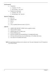
.../1GB DDR II 533MHz memory upgrades modules Additional 65W AC adaptor Additional eight-cell Li-ion battery pack External USB floppy drive Second 6-cell battery pack (AcerMedia Bay, for TravelMate 4650 series) DVD-Super Multi double layer drive (AcerMedia Bay, for TravelMate 4650 series) Acer ezDock (for TravelMate 4650 series) NOTE: The specifications listed above are for reference only.
.../1GB DDR II 533MHz memory upgrades modules Additional 65W AC adaptor Additional eight-cell Li-ion battery pack External USB floppy drive Second 6-cell battery pack (AcerMedia Bay, for TravelMate 4650 series) DVD-Super Multi double layer drive (AcerMedia Bay, for TravelMate 4650 series) Acer ezDock (for TravelMate 4650 series) NOTE: The specifications listed above are for reference only.

TravelMate 4150 / 4650 Service Guide
Page 19
... on page 10 # Icon Item # Item 1 Speakers 2 Bluetooth communication button/indicator 3 Wireless communication button/indicator 4 Power indicator 5 Battery indicator 6 Latch Description Description Left and right speakers deliver stereo audio output. Lights to indicate the status of wireless LAN communications. Locks and releases the ...
... on page 10 # Icon Item # Item 1 Speakers 2 Bluetooth communication button/indicator 3 Wireless communication button/indicator 4 Power indicator 5 Battery indicator 6 Latch Description Description Left and right speakers deliver stereo audio output. Lights to indicate the status of wireless LAN communications. Locks and releases the ...

TravelMate 4150 / 4650 Service Guide
Page 23
... of the fan. Houses the computer's hard disk (secured by a screw). Helps keep the computer cool. Bottom View # Item # Item 1 Memory compartment 2 Hard disk bay 3 Battery release latch 4 Battery bay 5 Cooling fan 6 AcerMedia Bay (for TravelMate 4650 Series) 14 Chapter 1 NOTE: Do not cover or obstruct the opening of latch module. (for...
... of the fan. Houses the computer's hard disk (secured by a screw). Helps keep the computer cool. Bottom View # Item # Item 1 Memory compartment 2 Hard disk bay 3 Battery release latch 4 Battery bay 5 Cooling fan 6 AcerMedia Bay (for TravelMate 4650 Series) 14 Chapter 1 NOTE: Do not cover or obstruct the opening of latch module. (for...

TravelMate 4150 / 4650 Service Guide
Page 30
...the upper-right above the keyboard, and four indicators at the front panel. Charg2i.nFgul:lythcehalirgghetds: hows amber when the battery is activated. Icon Item Icon Function Caps Lock Description Description Lights when Caps Lock is charging. 2. Icon Function Description Bluetooth... Indicators The computer has three easy-to-read status icons on . 12..BFCauhtlaltyergrcyihnaignr:gdeicda:tor Lights when the battery is being charged. 1. The power, battery, and wireless communication status indicators are visible even when the LCD display is closed. Charging: 2. Cahrgaergdin: ...
...the upper-right above the keyboard, and four indicators at the front panel. Charg2i.nFgul:lythcehalirgghetds: hows amber when the battery is activated. Icon Item Icon Function Caps Lock Description Description Lights when Caps Lock is charging. 2. Icon Function Description Bluetooth... Indicators The computer has three easy-to-read status icons on . 12..BFCauhtlaltyergrcyihnaignr:gdeicda:tor Lights when the battery is being charged. 1. The power, battery, and wireless communication status indicators are visible even when the LCD display is closed. Charging: 2. Cahrgaergdin: ...
TravelMate 4150 / 4650 Service Guide
Page 35
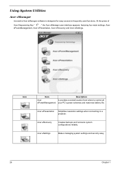
... r eSettinIgt provides a central l"ocaLtiaonufronmcwhherektoecoynstro"l alol n page 1 AceePorweerMPanoagw emeentrMyouar PnC'as pgoweermscheemnestand maximise battery life. At the press of Acer Empowering Key " ," the Acer eManager user interface appears, featuring four main settings: Acer "Acer eMePaonwageerMr"aonnapgaegmee1n9t, Acer ePresentation, Acer eRecovery and Acer eSettings. Using System Utilities tion Description Acer eManager Innovative Acer eManager software is designed for easy access to a AAcceerreeRPerceosveenprryotjeacttori...
... r eSettinIgt provides a central l"ocaLtiaonufronmcwhherektoecoynstro"l alol n page 1 AceePorweerMPanoagw emeentrMyouar PnC'as pgoweermscheemnestand maximise battery life. At the press of Acer Empowering Key " ," the Acer eManager user interface appears, featuring four main settings: Acer "Acer eMePaonwageerMr"aonnapgaegmee1n9t, Acer ePresentation, Acer eRecovery and Acer eSettings. Using System Utilities tion Description Acer eManager Innovative Acer eManager software is designed for easy access to a AAcceerreeRPerceosveenprryotjeacttori...
TravelMate 4150 / 4650 Service Guide
Page 44
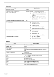
... 12 function keys Four easy-launch buttons Two front access LED buttons Specification KB 910 Standard keyboard w launch button embeded T Acer FineTouchTM keyboard with 5degree curve, 88/89-key Windows keyboard T Ergonomically-centerd touchpad pointing device with 4-way Internet scroll function Yes... browser T email with LED T Empowering key T one user-programmable button T WLAN LED button T Bluetooth LED button Battery Item Vendor & model name Battery Type Pack capacity Cell voltage Number of battery cell Pin 1 Pin 2 Pin 3 Pin 4 Pin 5 Pin 6 Pin 7 Specification Sony/Panasonic/Sanyo Li-ion ...
... 12 function keys Four easy-launch buttons Two front access LED buttons Specification KB 910 Standard keyboard w launch button embeded T Acer FineTouchTM keyboard with 5degree curve, 88/89-key Windows keyboard T Ergonomically-centerd touchpad pointing device with 4-way Internet scroll function Yes... browser T email with LED T Empowering key T one user-programmable button T WLAN LED button T Bluetooth LED button Battery Item Vendor & model name Battery Type Pack capacity Cell voltage Number of battery cell Pin 1 Pin 2 Pin 3 Pin 4 Pin 5 Pin 6 Pin 7 Specification Sony/Panasonic/Sanyo Li-ion ...

TravelMate 4150 / 4650 Service Guide
Page 46
... Delta 3-pin, 19V 3.95A, 64W Hipro 3-pin, 19V 3.95A, 65W Lite-on 3-pin, 19V 3.95A, 60W Details 65W 8-cell Li-ion battery pack 42W 6-cell Li-ion 2nd battery pack T 5-hour battery life on Intel 915GM models T 3.5-hour charge-in-use T 2.5-hour rapid charge Input Requirements Maximum input current (A, @100Vac, full load) 1.8A...
... Delta 3-pin, 19V 3.95A, 64W Hipro 3-pin, 19V 3.95A, 65W Lite-on 3-pin, 19V 3.95A, 60W Details 65W 8-cell Li-ion battery pack 42W 6-cell Li-ion 2nd battery pack T 5-hour battery life on Intel 915GM models T 3.5-hour charge-in-use T 2.5-hour rapid charge Input Requirements Maximum input current (A, @100Vac, full load) 1.8A...

TravelMate 4150 / 4650 Service Guide
Page 47
.... Dimensions and Weight Item Deminsions Weight Details 336.4 x 284.5 x 32 mm ( with ID )-34.5 mm 2.84kg(6.26 lbs) 15°® SXGA+, 8-cell Li-Ion Battery / DVD burner (With ID) Environmental Requirements Item Temperature Operating Non-operating Humidity Operating Altitude Specification 0°C ~ +40°C -20 ~ +65°C (storage package) 20% ~ 80...
.... Dimensions and Weight Item Deminsions Weight Details 336.4 x 284.5 x 32 mm ( with ID )-34.5 mm 2.84kg(6.26 lbs) 15°® SXGA+, 8-cell Li-Ion Battery / DVD burner (With ID) Environmental Requirements Item Temperature Operating Non-operating Humidity Operating Altitude Specification 0°C ~ +40°C -20 ~ +65°C (storage package) 20% ~ 80...

TravelMate 4150 / 4650 Service Guide
Page 65
Remove the battery pack. Please pay attention to the explanation below is for service purpose. NOTE: The screws used to the system and all power and signal cables from the system. 3. General Information Before You Begin Before proceeding with the disassembly procedure, make sure that you disassemble the system for your reference. Please group same type of screw together as you do the following: 1. Unplug the AC adapter and all peripherals. 2. The image below . 56 Chapter 3 Turn off the power to secure bottom case and upper case are more than one type.
Remove the battery pack. Please pay attention to the explanation below is for service purpose. NOTE: The screws used to the system and all power and signal cables from the system. 3. General Information Before You Begin Before proceeding with the disassembly procedure, make sure that you disassemble the system for your reference. Please group same type of screw together as you do the following: 1. Unplug the AC adapter and all peripherals. 2. The image below . 56 Chapter 3 Turn off the power to secure bottom case and upper case are more than one type.

TravelMate 4150 / 4650 Service Guide
Page 66
Slide the battery latch as shown then remove the battery pack. Unlock the battery lock. 2. Chapter 3 57 Removing the Battery Pack 1.
Slide the battery latch as shown then remove the battery pack. Unlock the battery lock. 2. Chapter 3 57 Removing the Battery Pack 1.
TravelMate 4150 / 4650 Service Guide
Page 77
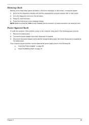
Go to main board. 2. Follow the instructions in the test items. 3. Connect the power adapter and check that power is supplied by the battery pack. then check that power is fully installed into the connector. A loose connection can cause an error. Power System Check To verify the ...symptom of the following list: T "Check the Power Adapter" on page 69 T "Check the Battery Pack" on page 70 Chapter 4 68 Press F2 in the following power sources: 1. NOTE: Make sure that the DIMM is supplied. 3. Boot from the...
Go to main board. 2. Follow the instructions in the test items. 3. Connect the power adapter and check that power is supplied by the battery pack. then check that power is fully installed into the connector. A loose connection can cause an error. Power System Check To verify the ...symptom of the following list: T "Check the Power Adapter" on page 69 T "Check the Battery Pack" on page 70 Chapter 4 68 Press F2 in the following power sources: 1. NOTE: Make sure that the DIMM is supplied. 3. Boot from the...

TravelMate 4150 / 4650 Service Guide
Page 78
... adapter for correct continuity and installation. 4. If the voltage is not correct, replace the power adapter. 2. T If the voltage is not corrected, see "Check the Battery Pack" on page 70. 69 Chapter 4 T If the problem is not correct, go to +20.5V Pin 2: 0V, Ground 1. If the operational charge does not...
... adapter for correct continuity and installation. 4. If the voltage is not correct, replace the power adapter. 2. T If the voltage is not corrected, see "Check the Battery Pack" on page 70. 69 Chapter 4 T If the problem is not correct, go to +20.5V Pin 2: 0V, Ground 1. If the operational charge does not...

TravelMate 4150 / 4650 Service Guide
Page 79
...steady pressure is still less than 50% of time. Chapter 4 70 In Power Meter, confirm that has less than 7.5 Vdc after recharging, replace the battery. Touchpad Check If the touchpad doesn't work, do the following: From Software: 1. This symptom is on the screen for both... battery and adapter. 4. Check the Battery Pack To check the battery pack, do the following figure 3. Repeat the steps 1 and 2, for a short time. After you identify first the problem is not a ...
...steady pressure is still less than 50% of time. Chapter 4 70 In Power Meter, confirm that has less than 7.5 Vdc after recharging, replace the battery. Touchpad Check If the touchpad doesn't work, do the following: From Software: 1. This symptom is on the screen for both... battery and adapter. 4. Check the Battery Pack To check the battery pack, do the following figure 3. Repeat the steps 1 and 2, for a short time. After you identify first the problem is not a ...
TravelMate 4150 / 4650 Service Guide
Page 81
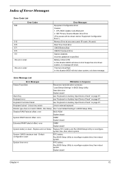
... critical High In this situation BIOS will be shown before "Equipment Configuration Error") Memory Error at offset: nnnn DIMM System board System battery is specified. Hard disk drive System board Stuck Key see "Keyboard or Auxiliary Input Device Check" on page 67. Run Setup Run...RAM Failed at offset: nnnn DIMM System board Extended RAM Failed at xxxx:xxxx:xxxxh (R:xxxxh, W:xxxxh) Real Time Clock Error CMOS Battery Bad CMOS Checksum Error System disabled. Error Message List Error Messages FRU/Action in BIOS Setup Utility. Keyboard locked - System board Chapter ...
... critical High In this situation BIOS will be shown before "Equipment Configuration Error") Memory Error at offset: nnnn DIMM System board System battery is specified. Hard disk drive System board Stuck Key see "Keyboard or Auxiliary Input Device Check" on page 67. Run Setup Run...RAM Failed at offset: nnnn DIMM System board Extended RAM Failed at xxxx:xxxx:xxxxh (R:xxxxh, W:xxxxh) Real Time Clock Error CMOS Battery Bad CMOS Checksum Error System disabled. Error Message List Error Messages FRU/Action in BIOS Setup Utility. Keyboard locked - System board Chapter ...

TravelMate 4150 / 4650 Service Guide
Page 82
... Device Address Conflict Run "Load Default Settings" in BIOS Setup Utility. Diskette drive Hard disk drive System board 73 Chapter 4 RTC battery System board Memory size found Enter Setup and see if fixed disk and drive A: are properly identified. Error Message List Error Messages ...FRU/Action in BIOS Setup Utility System cache error - RTC battery System board Operating system not found by POST differed from CMOS Run "Load Default Settings" in BIOS Setup Utility See "External Diskette ...
... Device Address Conflict Run "Load Default Settings" in BIOS Setup Utility. Diskette drive Hard disk drive System board 73 Chapter 4 RTC battery System board Memory size found Enter Setup and see if fixed disk and drive A: are properly identified. Error Message List Error Messages ...FRU/Action in BIOS Setup Utility System cache error - RTC battery System board Operating system not found by POST differed from CMOS Run "Load Default Settings" in BIOS Setup Utility See "External Diskette ...

TravelMate 4150 / 4650 Service Guide
Page 83
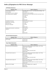
... Message List No beep Error Messages FRU/Action in Sequence No beep, power-on indicator turns off and LCD is blank. LED board. Power source (battery pack and power adapter). Reconnect the LCD connectors LCD inverter ID LCD cable LCD inverter LCD System board No beep, power-on indicator turns on... and a blinking cursor shown on LCD during POST but system runs correctly. Power source (battery pack and power adapter). No beep, power-on indicator turns on page 68.
... Message List No beep Error Messages FRU/Action in Sequence No beep, power-on indicator turns off and LCD is blank. LED board. Power source (battery pack and power adapter). Reconnect the LCD connectors LCD inverter ID LCD cable LCD inverter LCD System board No beep, power-on indicator turns on... and a blinking cursor shown on LCD during POST but system runs correctly. Power source (battery pack and power adapter). No beep, power-on indicator turns on page 68.
TravelMate 4150 / 4650 Service Guide
Page 85
... and power adapter). See "Power System Check" on page 68. See "Power System Check" on page 70. Battery pack Power adapter Hard drive & battery connection board System board Power source (battery pack and power adapter). The system doesn't power-off or on, but system runs correctly Reconnect the inverter board Inverter board System...
... and power adapter). See "Power System Check" on page 68. See "Power System Check" on page 70. Battery pack Power adapter Hard drive & battery connection board System board Power source (battery pack and power adapter). The system doesn't power-off or on, but system runs correctly Reconnect the inverter board Inverter board System...
TravelMate 4150 / 4650 Service Guide
Page 86
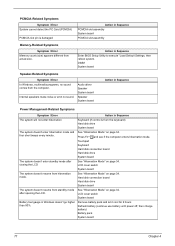
...Hard disk drive System board The system doesn't enter standby mode after opening the LCD. Remove battery pack and let it cool for 2 hours Refresh battery (continue use battery until power off, then charge battery) Battery pack System board 77 Chapter 4 See "Hibernation Mode" on page 34. PCMCIA-Related Symptoms... system doesn't resume from standby mode after closing the LCD See "Hibernation Mode" on page 34. LCD cover switch System board Battery fuel gauge in Sequence Enter BIOS Setup Utility to execute "Load Default Settings, then reboot system. Press Fn+oand see if the...
...Hard disk drive System board The system doesn't enter standby mode after opening the LCD. Remove battery pack and let it cool for 2 hours Refresh battery (continue use battery until power off, then charge battery) Battery pack System board 77 Chapter 4 See "Hibernation Mode" on page 34. PCMCIA-Related Symptoms... system doesn't resume from standby mode after closing the LCD See "Hibernation Mode" on page 34. LCD cover switch System board Battery fuel gauge in Sequence Enter BIOS Setup Utility to execute "Load Default Settings, then reboot system. Press Fn+oand see if the...


