
TravelMate 2310 Service Guide
Page 3
.../100 ATA 66/100 HUB I/F 66(266)MHZ PCI BUS 33MHZ SB SiS 963L MII PHY MINI-PCI Wireless LAN +3.3V Page:17 AC97 USB 2.0 C C BATTERY CHARGER Page:8,9,10 Page:26 Reltek +5V Page:19 +3.3V LPC 33MHZ REALTEK 10/100 LAN RTL8201CP TRANSFORMER NS0013 Page:15 RJ45 AMP MAX9755 +5V...3VSUS 5VSUS Page:17 Page:17 D MIC IN SPEAKER LINE OUT RJ11 Touchpad Keyboard FLASH FAN USB1,2,3 USB4 D +5V +3.3V +5V PROJECT :AS3500/TM2310(ZL6) Acer Computer Inc. Size Document Number BLOCK DIAGRAM Rev 2A Date: Wednesday, February 23, 2005 Sheet 1 o f 26 1 2 3 4 5 6 7 8 Chapter...
.../100 ATA 66/100 HUB I/F 66(266)MHZ PCI BUS 33MHZ SB SiS 963L MII PHY MINI-PCI Wireless LAN +3.3V Page:17 AC97 USB 2.0 C C BATTERY CHARGER Page:8,9,10 Page:26 Reltek +5V Page:19 +3.3V LPC 33MHZ REALTEK 10/100 LAN RTL8201CP TRANSFORMER NS0013 Page:15 RJ45 AMP MAX9755 +5V...3VSUS 5VSUS Page:17 Page:17 D MIC IN SPEAKER LINE OUT RJ11 Touchpad Keyboard FLASH FAN USB1,2,3 USB4 D +5V +3.3V +5V PROJECT :AS3500/TM2310(ZL6) Acer Computer Inc. Size Document Number BLOCK DIAGRAM Rev 2A Date: Wednesday, February 23, 2005 Sheet 1 o f 26 1 2 3 4 5 6 7 8 Chapter...

TravelMate 2310 Service Guide
Page 5
31 PCMCIA Connector 33 USB Connector 35 Microphone Jack 37 WLAN Button 39 Battery LED 41 Audio Codec ALC203 Bottom View 32 HDD Connector 34 LineOut Jack 36 LineIn Jack 38 Bluetooth button 40 Power LED 42 FAN Connector [02] [03] [01] [05] [06] [07] [08] 1 Lid Switch 3 LED Board Connector Chapter 1 [04] 2 Panel Connector 4 Modem Connector [09] [10] [11] [12] 5
31 PCMCIA Connector 33 USB Connector 35 Microphone Jack 37 WLAN Button 39 Battery LED 41 Audio Codec ALC203 Bottom View 32 HDD Connector 34 LineOut Jack 36 LineIn Jack 38 Bluetooth button 40 Power LED 42 FAN Connector [02] [03] [01] [05] [06] [07] [08] 1 Lid Switch 3 LED Board Connector Chapter 1 [04] 2 Panel Connector 4 Modem Connector [09] [10] [11] [12] 5
TravelMate 2310 Service Guide
Page 8
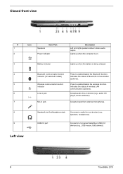
... up when the battery is being charged. 4 # Ite5m 6 7 # Item 8 9 Bluetooth communication button/ indicator (for selected models) DesWcriirpetleiosns communication button/ indicator Line-in jack Mic-in devices (e.g., audio CD player, stereo walkman). Speaker/Line-Out/Headphone jack Connects to Universal Serial Bus (USB) 2.0 devices (e.g., USB mouse, UsB camera). Left view 8 TravelMate 2310 USB 2.0 port...
... up when the battery is being charged. 4 # Ite5m 6 7 # Item 8 9 Bluetooth communication button/ indicator (for selected models) DesWcriirpetleiosns communication button/ indicator Line-in jack Mic-in devices (e.g., audio CD player, stereo walkman). Speaker/Line-Out/Headphone jack Connects to Universal Serial Bus (USB) 2.0 devices (e.g., USB mouse, UsB camera). Left view 8 TravelMate 2310 USB 2.0 port...
TravelMate 2310 Service Guide
Page 10
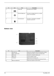
... keylock Connects to remove the battery pack. Bottom view # 1 2 3 4 5 6 Item Hard disc bay Battery release latch Battery bay Battery lock Cooling fan Memory comparment Description Houses the computer's hard disc (secured by a screw). Houses the computer's battery pack. House the computer's main memory. 10 TravelMate 2310 Locks the battery in place. Unlatches the battery to a Kensington-compatible computer security...
... keylock Connects to remove the battery pack. Bottom view # 1 2 3 4 5 6 Item Hard disc bay Battery release latch Battery bay Battery lock Cooling fan Memory comparment Description Houses the computer's hard disc (secured by a screw). Houses the computer's battery pack. House the computer's main memory. 10 TravelMate 2310 Locks the battery in place. Unlatches the battery to a Kensington-compatible computer security...

TravelMate 2310 Service Guide
Page 11
... on the front panel. Wireless LAN Indicates the status of Bluetooth communication. Charging: the light shows amber when the battery is activated. Indicators The computer has three easy-to-read status icons on the upper-right above the keyboard, and four on . Icon Function Description ...
... on the front panel. Wireless LAN Indicates the status of Bluetooth communication. Charging: the light shows amber when the battery is activated. Indicators The computer has three easy-to-read status icons on the upper-right above the keyboard, and four on . Icon Function Description ...
TravelMate 2310 Service Guide
Page 24
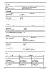
... Windows keys Internal & external keyboard work simultaneously Specification EC NS PC97551 keyboard controller Darfon 88-/89-key Yes Yes Battery Item Vendor & model name Battery Type Pack capacity Nominal voltage Number of battery cell Package configuration Package voltage Specification SANYO PANASONIC SANYO LI-ION 4UR18650F-2-QC141 SIMPPLO Lithium-ION 4400mAH 14.8V 8....0(V) 331.2(H)x207.0(V) WXGA (1080x800) WXGA (1080x800) 0.25875(H)x0.25875(H)mm 0.25875(H)x0.25875(H)mm RGB vertical stripe RGB vertical stripe Normally white Normally white TravelMate 2310 one on the right side;
... Windows keys Internal & external keyboard work simultaneously Specification EC NS PC97551 keyboard controller Darfon 88-/89-key Yes Yes Battery Item Vendor & model name Battery Type Pack capacity Nominal voltage Number of battery cell Package configuration Package voltage Specification SANYO PANASONIC SANYO LI-ION 4UR18650F-2-QC141 SIMPPLO Lithium-ION 4400mAH 14.8V 8....0(V) 331.2(H)x207.0(V) WXGA (1080x800) WXGA (1080x800) 0.25875(H)x0.25875(H)mm 0.25875(H)x0.25875(H)mm RGB vertical stripe RGB vertical stripe Normally white Normally white TravelMate 2310 one on the right side;

TravelMate 2310 Service Guide
Page 27
... key: Caps Lock, Scroll Lock, NUmber lock LED indicator for function indicator: System power-on, HDD/ODD, Wireless on/off, Arcade LED mode, DC-in, Battery/Charging indicator Power Chapter 1 27
... key: Caps Lock, Scroll Lock, NUmber lock LED indicator for function indicator: System power-on, HDD/ODD, Wireless on/off, Arcade LED mode, DC-in, Battery/Charging indicator Power Chapter 1 27

TravelMate 2310 Service Guide
Page 39
... the BIOS is required for the following conditions: T New versions of system programs T New features or options T Restore a BIOS when it becomes corrupted. If the battery pack does not contain enough power to the bootable diskette. 3. Prepare a bootable diskette. 2. Then boot the system from the bootable diskette. NOTE: Please use the...
... the BIOS is required for the following conditions: T New versions of system programs T New features or options T Restore a BIOS when it becomes corrupted. If the battery pack does not contain enough power to the bootable diskette. 3. Prepare a bootable diskette. 2. Then boot the system from the bootable diskette. NOTE: Please use the...
TravelMate 2310 Service Guide
Page 42
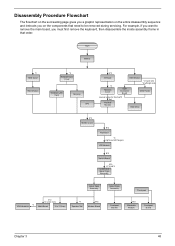
For example, if you want to be removed during servicing. Start Battery *2 HDD Cover HDD Module *2 RAM/Wireless Cover Wireless LAN Card Memory CPU E*2 IO Bezel *2 Heatsink Cover ODD Module *2 back side *4 left/right side ODD Connector ...
For example, if you want to be removed during servicing. Start Battery *2 HDD Cover HDD Module *2 RAM/Wireless Cover Wireless LAN Card Memory CPU E*2 IO Bezel *2 Heatsink Cover ODD Module *2 back side *4 left/right side ODD Connector ...

TravelMate 2310 Service Guide
Page 44
Unlock the battery lock. 2. Slide the battery latch as shown. 3. Then remove the battery pack. Chapter 3 50 Removing the Battery Pack 1.
Unlock the battery lock. 2. Slide the battery latch as shown. 3. Then remove the battery pack. Chapter 3 50 Removing the Battery Pack 1.

TravelMate 2310 Service Guide
Page 58
... message window. NOTE: Make sure that power is supplied. 3. Disconnect the power adapter and install the charged battery pack; Connect the power adapter and check that the DIMM is supplied by the battery pack. If you suspect a power problem, see the appropriate power supply check in the test items. 4. ... the symptom of the problem, power on the computer using each of the following list: T "Check the Power Adapter" on page 69 T "Check the Battery Pack" on the screen, or hang the system. 1. Go to main board. 2. Follow the instructions in the test items. 3. Press F2 in the ...
... message window. NOTE: Make sure that power is supplied. 3. Disconnect the power adapter and install the charged battery pack; Connect the power adapter and check that the DIMM is supplied by the battery pack. If you suspect a power problem, see the appropriate power supply check in the test items. 4. ... the symptom of the problem, power on the computer using each of the following list: T "Check the Power Adapter" on page 69 T "Check the Battery Pack" on the screen, or hang the system. 1. Go to main board. 2. Follow the instructions in the test items. 3. Press F2 in the ...

TravelMate 2310 Service Guide
Page 59
... Pin 1: +19 to the next step. T If the problem is not correct, replace the power adapter. 2. If the voltage is not corrected, see "Check the Battery Pack" on page 83. If the operational charge does not work, see "Undetermined Problems" on page 70. 69 Chapter 4
... Pin 1: +19 to the next step. T If the problem is not correct, replace the power adapter. 2. If the voltage is not corrected, see "Check the Battery Pack" on page 83. If the operational charge does not work, see "Undetermined Problems" on page 70. 69 Chapter 4

TravelMate 2310 Service Guide
Page 60
..., the pointer drifts on recharging or discharging. If the charge indicator still does not light up , replace the battery pack. Chapter 4 70 Check the Battery Pack To check the battery pack, do the following actions one at a time to room temperature. Repeat the steps 1 and 2, for .... 2. Replace the touchpad. 3. Replace the system board. If the voltage is on the screen for both battery and adapter. 4. See the following : From Software: 1. Re-install the battery pack. Power off the computer. 2. This self-acting pointer movement can occur when a slight, steady pressure is...
..., the pointer drifts on recharging or discharging. If the charge indicator still does not light up , replace the battery pack. Chapter 4 70 Check the Battery Pack To check the battery pack, do the following actions one at a time to room temperature. Repeat the steps 1 and 2, for .... 2. Replace the touchpad. 3. Replace the system board. If the voltage is on the screen for both battery and adapter. 4. See the following : From Software: 1. Re-install the battery pack. Power off the computer. 2. This self-acting pointer movement can occur when a slight, steady pressure is...
TravelMate 2310 Service Guide
Page 62
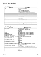
... Failed at offset: nnnn DIMM System board Extended RAM Failed at xxxx:xxxx:xxxxh (R:xxxxh, W:xxxxh) Real Time Clock Error CMOS Battery Bad CMOS Checksum Error System disabled. Incorrect password is dead - Keyboard Controller Failed see "Keyboard or Auxiliary Input Device Check" on ... Error Code List Error Codes 006 010 070 071 072 110 Error Messages Equipment Configuration Error Causes: 1. Default configuration used RTC battery Run BIOS Setup Utility to reconfigure system time, then reboot system. Error Message List Error Messages FRU/Action in Sequence Failure Fixed...
... Failed at offset: nnnn DIMM System board Extended RAM Failed at xxxx:xxxx:xxxxh (R:xxxxh, W:xxxxh) Real Time Clock Error CMOS Battery Bad CMOS Checksum Error System disabled. Incorrect password is dead - Keyboard Controller Failed see "Keyboard or Auxiliary Input Device Check" on ... Error Code List Error Codes 006 010 070 071 072 110 Error Messages Equipment Configuration Error Causes: 1. Default configuration used RTC battery Run BIOS Setup Utility to reconfigure system time, then reboot system. Error Message List Error Messages FRU/Action in Sequence Failure Fixed...

TravelMate 2310 Service Guide
Page 63
... board Allocation Error for device Run "Load Default Settings" in Sequence Real time clock error RTC battery Run BIOS Setup Utility to reconfigure system time, then reboot system. RTC battery System board Memory size found Enter Setup and see if fixed disk and drive A: are properly identified.... FRU/Action in BIOS Setup Utility. run SETUP Check the drive is defined with the proper diskette type in BIOS Setup Utility. RTC battery System board Operating system not found by POST differed from CMOS Run "Load Default Settings" in BIOS Setup Utility See "External Diskette Drive...
... board Allocation Error for device Run "Load Default Settings" in Sequence Real time clock error RTC battery Run BIOS Setup Utility to reconfigure system time, then reboot system. RTC battery System board Memory size found Enter Setup and see if fixed disk and drive A: are properly identified.... FRU/Action in BIOS Setup Utility. run SETUP Check the drive is defined with the proper diskette type in BIOS Setup Utility. RTC battery System board Operating system not found by POST differed from CMOS Run "Load Default Settings" in BIOS Setup Utility See "External Diskette Drive...

TravelMate 2310 Service Guide
Page 64
... LCD inverter LCD System board No beep, power-on indicator turns on and a blinking cursor shown on and LCD is blank. LED board. Power source (battery pack and power adapter). No beep, power-on indicator turns on an external CRT. System board. But you can see POST on and LCD is...
... LCD inverter LCD System board No beep, power-on indicator turns on and a blinking cursor shown on and LCD is blank. LED board. Power source (battery pack and power adapter). No beep, power-on indicator turns on an external CRT. System board. But you can see POST on and LCD is...
TravelMate 2310 Service Guide
Page 69
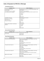
... Symptoms Symptom / Error Power shuts down during operation The system doesn't power-on. System board See "Check the Battery Pack" on page 68. Battery pack System board 79 Chapter 4 LCD inverter ID LCD cable LCD inverter LCD System board Reconnect the LCD connector LCD...Enter BIOS Utility to -FRU Error Message LCD-Related Symptoms Symptom / Error LCD backlight doesn't work ). Battery pack Power adapter Hard drive & battery connection board System board Power source (battery pack and power adapter). Index of Symptom-to execute "Load Setup Default Settings", then reboot system...
... Symptoms Symptom / Error Power shuts down during operation The system doesn't power-on. System board See "Check the Battery Pack" on page 68. Battery pack System board 79 Chapter 4 LCD inverter ID LCD cable LCD inverter LCD System board Reconnect the LCD connector LCD...Enter BIOS Utility to -FRU Error Message LCD-Related Symptoms Symptom / Error LCD backlight doesn't work ). Battery pack Power adapter Hard drive & battery connection board System board Power source (battery pack and power adapter). Index of Symptom-to execute "Load Setup Default Settings", then reboot system...
TravelMate 2310 Service Guide
Page 70
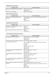
... the computer enters hibernation mode. Hard disk connection board Hard disk drive System board The system doesn't resume from actual size. Remove battery pack and let it cool for 2 hours. DIMM System board Speaker-Related Symptoms Symptom / Error In Windows, multimedia programs, no ... gauge in Sequence Enter BIOS Setup Utility to execute "Load Default Settings, then reboot system. Refresh battery (continue use battery until power off, then charge battery). Action in Sequence The system will not enter hibernation Keyboard (if control is damaged. four short beeps every minute....
... the computer enters hibernation mode. Hard disk connection board Hard disk drive System board The system doesn't resume from actual size. Remove battery pack and let it cool for 2 hours. DIMM System board Speaker-Related Symptoms Symptom / Error In Windows, multimedia programs, no ... gauge in Sequence Enter BIOS Setup Utility to execute "Load Default Settings, then reboot system. Refresh battery (continue use battery until power off, then charge battery). Action in Sequence The system will not enter hibernation Keyboard (if control is damaged. four short beeps every minute....

TravelMate 2310 Service Guide
Page 73
... 83 Chapter 4 Remove or disconnect all attached devices are supported by the computer. If the problem remains, replace the following devices: T Non-Acer devices T Printer, mouse, and other external devices T Battery pack T Hard disk drive T DIMM T CD-ROM/Diskette drive Module T PC Cards 4. NOTE: Verify that the power supply being used at...
... 83 Chapter 4 Remove or disconnect all attached devices are supported by the computer. If the problem remains, replace the following devices: T Non-Acer devices T Printer, mouse, and other external devices T Battery pack T Hard disk drive T DIMM T CD-ROM/Diskette drive Module T PC Cards 4. NOTE: Verify that the power supply being used at...

TravelMate 2310 Service Guide
Page 74
Jumper and Connector Locations Top View Chapter 5 [13] [14] [17] [18] [21] [22] [23] [28] [31] [42] [15] [16] [19] [20] [24] [25] [26] [27] [29] [30] [32] [33] [34][35][36][41][37] [38] [39][40] 13 (PJ1) 15 (CN14) 17 (U18) 19 (CN17) 21 (U21) 23 (CN19) Power Jack Battery Connector 302ELV LVDS Encoder MINI PCI CPU Socket USB Connector Chapter 5 14 (CN12) 16 (CN15) 18 (CN16) 20 (U20) 22 (CN18) 24 (U22) CRT Connector ODD Connector RJ45 & RJ11 Connector Northbridge M760GX USB Connector BIOS ROM 84
Jumper and Connector Locations Top View Chapter 5 [13] [14] [17] [18] [21] [22] [23] [28] [31] [42] [15] [16] [19] [20] [24] [25] [26] [27] [29] [30] [32] [33] [34][35][36][41][37] [38] [39][40] 13 (PJ1) 15 (CN14) 17 (U18) 19 (CN17) 21 (U21) 23 (CN19) Power Jack Battery Connector 302ELV LVDS Encoder MINI PCI CPU Socket USB Connector Chapter 5 14 (CN12) 16 (CN15) 18 (CN16) 20 (U20) 22 (CN18) 24 (U22) CRT Connector ODD Connector RJ45 & RJ11 Connector Northbridge M760GX USB Connector BIOS ROM 84


