TravelMate 2000/2500 Service Guide
Page 2
Revision History Please refer to the table below for the updates made on page 21 II Date 2004/04/21 Chapter Chapter 1 Updates Add description about modem chipset on TravelMate 2000/2500 service guide.
Revision History Please refer to the table below for the updates made on page 21 II Date 2004/04/21 Chapter Chapter 1 Updates Add description about modem chipset on TravelMate 2000/2500 service guide.

TravelMate 2000/2500 Service Guide
Page 7
... Keyboard 13 Special keys 13 Hot Keys 16 Hardware Specifications and Configurations 19 Chapter 2 System Utilities 34 BIOS Setup Utility 34 Navigating the BIOS Utility 35 Information 36 Main 37 Advanced 39 Security 41 Boot 45 Exit 46 BIOS Flash Utility 47 Chapter 3 Machine Disassembly and Replacement 48 General Information 49 Before You Begin 49 Disassembly Procedure Flowchart 50 Removing the Battery 52 Removing the Memory Module 53 Removing the Wireless LAN Board and the Modem Board 54 Removing the Hard Disk Drive Module 55 Disassembling...
... Keyboard 13 Special keys 13 Hot Keys 16 Hardware Specifications and Configurations 19 Chapter 2 System Utilities 34 BIOS Setup Utility 34 Navigating the BIOS Utility 35 Information 36 Main 37 Advanced 39 Security 41 Boot 45 Exit 46 BIOS Flash Utility 47 Chapter 3 Machine Disassembly and Replacement 48 General Information 49 Before You Begin 49 Disassembly Procedure Flowchart 50 Removing the Battery 52 Removing the Memory Module 53 Removing the Wireless LAN Board and the Modem Board 54 Removing the Hard Disk Drive Module 55 Disassembling...

TravelMate 2000/2500 Service Guide
Page 8
... ODD Module(1 68 Removing the ODD Module(2 68 Removing the HDD Bracket 69 Removing the Main Board 69 Removing the DC Board 70 Removing the I/O Port Bracket 70 Removing the PCMCIA Slot 71 Removing the Speaker Set 72 System Upgrade Procedure 73 Base Unit to Wireless Unit 73 Chapter 4 Troubleshooting 74 System Check Procedures 75 External Diskette Drive Check 75 External CD-ROM Drive Check 75 Keyboard or Auxiliary Input Device Check 75 Memory check 76 Power...
... ODD Module(1 68 Removing the ODD Module(2 68 Removing the HDD Bracket 69 Removing the Main Board 69 Removing the DC Board 70 Removing the I/O Port Bracket 70 Removing the PCMCIA Slot 71 Removing the Speaker Set 72 System Upgrade Procedure 73 Base Unit to Wireless Unit 73 Chapter 4 Troubleshooting 74 System Check Procedures 75 External Diskette Drive Check 75 External CD-ROM Drive Check 75 Keyboard or Auxiliary Input Device Check 75 Memory check 76 Power...
TravelMate 2000/2500 Service Guide
Page 9
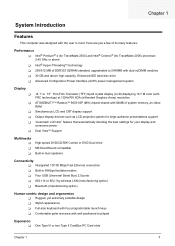
... LCD dim" feature that automatically deciding the best settings for your display and conserves power Dual ViewTM Support Multimedia T T T High-speed DVD/CD-RW Combo or DVD-Dual drive MS DirectSound compatible Built-in dual speakers Connectivity T Intergrated 10/100 Mbps Fast Ethernet connection T Built-in 56Kbps fax/data modem T Four USB (Universal Serial Bus) 2.0 ports T 802.11b or 802.11g wireless LAN (manufacturing option) T Bluetooth (manufacturing option...
... LCD dim" feature that automatically deciding the best settings for your display and conserves power Dual ViewTM Support Multimedia T T T High-speed DVD/CD-RW Combo or DVD-Dual drive MS DirectSound compatible Built-in dual speakers Connectivity T Intergrated 10/100 Mbps Fast Ethernet connection T Built-in 56Kbps fax/data modem T Four USB (Universal Serial Bus) 2.0 ports T 802.11b or 802.11g wireless LAN (manufacturing option) T Bluetooth (manufacturing option...

TravelMate 2000/2500 Service Guide
Page 17
...Mic-in jack Accepts audio line-in devices (e.g., audio CD player, stereo walkman). Chapter 1 9 Rear Panel l # 1 2 3 4 5 6 7 8 9 Icon Port Power Jack Description Connects to an AC adapter Parallel port Connects to Universal Serial Bus (USB) 2.0 devices(e.g., USB mouse, USB camera). Network jack Connects to an Ethernet 10/100-based network Modem jack Connects to the phone line Speaker/Line-Out/ Headphone jack Connects to stay cool, even after prolonged use. Ventilation slot External display port USB port (four) Enables the computer to audio line-out devices (e.g., speakers...
...Mic-in jack Accepts audio line-in devices (e.g., audio CD player, stereo walkman). Chapter 1 9 Rear Panel l # 1 2 3 4 5 6 7 8 9 Icon Port Power Jack Description Connects to an AC adapter Parallel port Connects to Universal Serial Bus (USB) 2.0 devices(e.g., USB mouse, USB camera). Network jack Connects to an Ethernet 10/100-based network Modem jack Connects to the phone line Speaker/Line-Out/ Headphone jack Connects to stay cool, even after prolonged use. Ventilation slot External display port USB port (four) Enables the computer to audio line-out devices (e.g., speakers...
TravelMate 2000/2500 Service Guide
Page 24
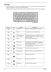
Accesses the notebook configuration utility. Press any key to save power. Fn-x Brightness up Increases the sound volume. Display toggle Screen blank Touchpad toggle Speaker toggle Switches display output between the power management scheme used by the computer (function available if supported by operating system). Hot Keys The computer employs hot keys or key combinations to access most of the hotkeys and their functions. Power Management Scheme Toggle Sleep Switches between the display screen, external monitor (if connected) and both the display screen and external ...
Accesses the notebook configuration utility. Press any key to save power. Fn-x Brightness up Increases the sound volume. Display toggle Screen blank Touchpad toggle Speaker toggle Switches display output between the power management scheme used by the computer (function available if supported by operating system). Hot Keys The computer employs hot keys or key combinations to access most of the hotkeys and their functions. Power Management Scheme Toggle Sleep Switches between the display screen, external monitor (if connected) and both the display screen and external ...

TravelMate 2000/2500 Service Guide
Page 28
BIOS Item Supported protocols BIOS password control Second Level Cache Item Cache controller Cache size 1st level cache control 2nd level cache control Cache scheme control Specification ACPI 1.0b, SMBIOS 2.3, PCI 2.2, Boot Block, PXE 2.0, Mobile PC2001, Hard Disk Password, INT 13h Extensions, PCI Bus Power Management interface Specification, EI Torito-Bootable CD-ROM Format Specification V1.0, Simple Boot Flag 1.0 Set by switch, see SW5 settings on Chapter 5. Specification Built-in CPU 128KB for Cerelon® CPU; 512KB for...
BIOS Item Supported protocols BIOS password control Second Level Cache Item Cache controller Cache size 1st level cache control 2nd level cache control Cache scheme control Specification ACPI 1.0b, SMBIOS 2.3, PCI 2.2, Boot Block, PXE 2.0, Mobile PC2001, Hard Disk Password, INT 13h Extensions, PCI Bus Power Management interface Specification, EI Torito-Bootable CD-ROM Format Specification V1.0, Simple Boot Flag 1.0 Set by switch, see SW5 settings on Chapter 5. Specification Built-in CPU 128KB for Cerelon® CPU; 512KB for...
TravelMate 2000/2500 Service Guide
Page 35
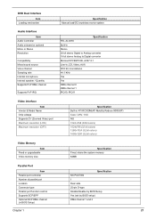
... 1024 x768 (32bit colors) 1024x768 (32 bit colors) 1280x1024 (32 bit colors) 1600x1200 (32 bit colors) Video Memory Item Fixed or upgradeable Video memory size Specification Fixed, share the system memory 64MB Parallel Port Item Parallel port controller Number of parallel port Location Connector type Parallel port function control Supports ECP/EPP Optional ECP DMA channel (in BIOS Setup) Specification NS PC87392 1 Rear side 25-pin D-type Enable/Disable by BIOS Setup Yes (set by BIOS setup) DMA channel 1 and 3 Chapter 1 27
... 1024 x768 (32bit colors) 1024x768 (32 bit colors) 1280x1024 (32 bit colors) 1600x1200 (32 bit colors) Video Memory Item Fixed or upgradeable Video memory size Specification Fixed, share the system memory 64MB Parallel Port Item Parallel port controller Number of parallel port Location Connector type Parallel port function control Supports ECP/EPP Optional ECP DMA channel (in BIOS Setup) Specification NS PC87392 1 Rear side 25-pin D-type Enable/Disable by BIOS Setup Yes (set by BIOS setup) DMA channel 1 and 3 Chapter 1 27

TravelMate 2000/2500 Service Guide
Page 40
Display Standby Mode Keyboard, built-in jack, one line-out ack, one microphone-in/ line-in touchpad, and an external PS/2 pointing device are idle for 15"LCD model with battery One Type III or two type II PCMCIA (PC Card) port, one RJ-11 port, one RJ-45 port, one DC-in port, one ECP parallel port, four USB ports, one FIR port. One Plastic Power-on, Standby, Battery Status, Media Access, CapsLock and NumLock Power 32...
Display Standby Mode Keyboard, built-in jack, one line-out ack, one microphone-in/ line-in touchpad, and an external PS/2 pointing device are idle for 15"LCD model with battery One Type III or two type II PCMCIA (PC Card) port, one RJ-11 port, one RJ-45 port, one DC-in port, one ECP parallel port, four USB ports, one FIR port. One Plastic Power-on, Standby, Battery Status, Media Access, CapsLock and NumLock Power 32...

TravelMate 2000/2500 Service Guide
Page 46
... is not displayed, and Summary Screen is disabled or enabled. Otherwise it will be in BIOS Setup Utility, this screen. Option: Enabled or Disabled Enables, disables Boot Menu during POST. NOTE: If user disables "PXE Boot from LAN" option in LCD only mode. Parameter System Time System Date System Memory Extended Memory VGA Memory Fast Boot Power on battery power). Extended Memory size=Total memory size-1MB Shows the VGA memory size. VGA Memory size=64/128MB Determines if Customer Logo will support an...
... is not displayed, and Summary Screen is disabled or enabled. Otherwise it will be in BIOS Setup Utility, this screen. Option: Enabled or Disabled Enables, disables Boot Menu during POST. NOTE: If user disables "PXE Boot from LAN" option in LCD only mode. Parameter System Time System Date System Memory Extended Memory VGA Memory Fast Boot Power on battery power). Extended Memory size=Total memory size-1MB Shows the VGA memory size. VGA Memory size=64/128MB Determines if Customer Logo will support an...
TravelMate 2000/2500 Service Guide
Page 50
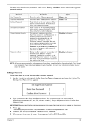
... the BIOS Setup Utility. Don't forget your password because the characters do not appear on boot parameter. 5. The Set Supervisor Password box appears: 2. Option Clear or Set Clear or Set Disabled or Enabled Disabled or Enabled NOTE: When you are prompted to enter a password, you are the default and suggested parameter settings. The password length can unlock the HDD. Settings in the "Enter New Password" field. Use the w andy keys to enable the Password on the screen. 3. This feature is available to enabled. Type a password...
... the BIOS Setup Utility. Don't forget your password because the characters do not appear on boot parameter. 5. The Set Supervisor Password box appears: 2. Option Clear or Set Clear or Set Disabled or Enabled Disabled or Enabled NOTE: When you are prompted to enter a password, you are the default and suggested parameter settings. The password length can unlock the HDD. Settings in the "Enter New Password" field. Use the w andy keys to enable the Password on the screen. 3. This feature is available to enabled. Type a password...

TravelMate 2000/2500 Service Guide
Page 51
... e key. Use the w and y keys to "Clear". 4. The Set Password box appears: 2. If desired, you have changed the settings, press u to save the changes and exit the BIOS Setup Utility. When you are done, press u to save the changes and exit the BIOS Setup Utility. Type the current password in the Enter Current Password field and press e. 3. When you can enable the Password on boot parameter. 6. The password setting is OK, the screen will display as following. Removing a Password...
... e key. Use the w and y keys to "Clear". 4. The Set Password box appears: 2. If desired, you have changed the settings, press u to save the changes and exit the BIOS Setup Utility. When you are done, press u to save the changes and exit the BIOS Setup Utility. Type the current password in the Enter Current Password field and press e. 3. When you can enable the Password on boot parameter. 6. The password setting is OK, the screen will display as following. Removing a Password...

TravelMate 2000/2500 Service Guide
Page 58
... Cover RTC Battery Keyboard F*6 LCD Module *2 Launch Board Second Fan J*3 Bracket Lower Case Assembly J*2 FDD Module J*5 F*10 D*4 Upper Case Assembly D*4 Wireless LAN Antenna Touchpad Cover J*3 Second Fan *4 Thermal Module CPU ODD Module J*4 HDD Bracket F*1 ODD Support Bracket *1 CPU Heatsink Plate J*7 VGA Thermal Plate Touchpad Button Pad D*2 ODD Bracket ODD *4 Main Board Touchpad Touchpad Scroll Key D*2 DC Board D*4 PCMCIA Slot Touchpad Cable Upper Case *2 Speaker Set Chapter 3 50 For example, if you want to be removed during servicing. Disassembly Procedure...
... Cover RTC Battery Keyboard F*6 LCD Module *2 Launch Board Second Fan J*3 Bracket Lower Case Assembly J*2 FDD Module J*5 F*10 D*4 Upper Case Assembly D*4 Wireless LAN Antenna Touchpad Cover J*3 Second Fan *4 Thermal Module CPU ODD Module J*4 HDD Bracket F*1 ODD Support Bracket *1 CPU Heatsink Plate J*7 VGA Thermal Plate Touchpad Button Pad D*2 ODD Bracket ODD *4 Main Board Touchpad Touchpad Scroll Key D*2 DC Board D*4 PCMCIA Slot Touchpad Cable Upper Case *2 Speaker Set Chapter 3 50 For example, if you want to be removed during servicing. Disassembly Procedure...

TravelMate 2000/2500 Service Guide
Page 80
.... 12. See "Removing the HDD Bracket" on page 63. 6. Tear off the tape fastening the speaker set . Then remove the four screws that secure the speaker set cable. See "Removing the VGA Thermal Plate" on page 67. 9. Removing the Speaker Set 1. See "Removing the CPU Heatsink Plate" on page 67. 8. See "Removing the ODD Module(2)" on page 56. 3. See "Removing the Middle Cover" on page...
.... 12. See "Removing the HDD Bracket" on page 63. 6. Tear off the tape fastening the speaker set . Then remove the four screws that secure the speaker set cable. See "Removing the VGA Thermal Plate" on page 67. 9. Removing the Speaker Set 1. See "Removing the CPU Heatsink Plate" on page 67. 8. See "Removing the ODD Module(2)" on page 56. 3. See "Removing the Middle Cover" on page...
TravelMate 2000/2500 Service Guide
Page 88
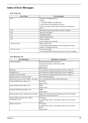
... Setup Run "Load Default Settings" in BIOS Setup Utility. System board Chapter 4 80 Keyboard error see "Keyboard or Auxiliary Input Device Check" on page 75. System timer error RTC battery Run BIOS Setup Utility to reconfigure system time, then reboot system. Keyboard Controller Failed see "Keyboard or Auxiliary Input Device Check" on page 75. Unlock key switch Unlock external keyboard Monitor type does not match CMOS - Index of Error Messages Error Code List Error Codes 006 010 070 071 072 110 Error Messages Equipment Configuration Error Causes: 1. Keyboard...
... Setup Run "Load Default Settings" in BIOS Setup Utility. System board Chapter 4 80 Keyboard error see "Keyboard or Auxiliary Input Device Check" on page 75. System timer error RTC battery Run BIOS Setup Utility to reconfigure system time, then reboot system. Keyboard Controller Failed see "Keyboard or Auxiliary Input Device Check" on page 75. Unlock key switch Unlock external keyboard Monitor type does not match CMOS - Index of Error Messages Error Code List Error Codes 006 010 070 071 072 110 Error Messages Equipment Configuration Error Causes: 1. Keyboard...

TravelMate 2000/2500 Service Guide
Page 91
... operation The system doesn't power-on page 76. System board See "Check the Battery Pack" on page 76. Keyboard (if contrast and brightness function key doesn't work LCD is too dark LCD brightness cannot be adjusted LCD contrast cannot be charged Action in characters Abnormal screen Wrong color displayed LCD has extra horizontal or vertical lines displayed. Battery pack Power adapter Hard drive & battery connection board System board Power source (battery pack and power adapter). Index of Symptom-to execute "Load Setup Default Settings", then reboot...
... operation The system doesn't power-on page 76. System board See "Check the Battery Pack" on page 76. Keyboard (if contrast and brightness function key doesn't work LCD is too dark LCD brightness cannot be adjusted LCD contrast cannot be charged Action in characters Abnormal screen Wrong color displayed LCD has extra horizontal or vertical lines displayed. Battery pack Power adapter Hard drive & battery connection board System board Power source (battery pack and power adapter). Index of Symptom-to execute "Load Setup Default Settings", then reboot...
TravelMate 2000/2500 Service Guide
Page 92
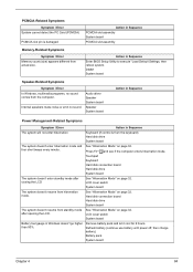
Action in Windows doesn't go higher than 90%. Press Fn+oand see if the computer enters hibernation mode. LCD cover switch System board Battery fuel gauge in Sequence Enter BIOS Setup Utility to execute "Load Default Settings, then reboot system. Audio driver Speaker System board Speaker System board Action in Sequence Power Management-Related Symptoms Symptom / Error Action in Sequence PCMCIA slot assembly System board PCMCIA slot assembly Memory-Related Symptoms Symptom / Error Memory count (size) appears different from...
Action in Windows doesn't go higher than 90%. Press Fn+oand see if the computer enters hibernation mode. LCD cover switch System board Battery fuel gauge in Sequence Enter BIOS Setup Utility to execute "Load Default Settings, then reboot system. Audio driver Speaker System board Speaker System board Action in Sequence Power Management-Related Symptoms Symptom / Error Action in Sequence PCMCIA slot assembly System board PCMCIA slot assembly Memory-Related Symptoms Symptom / Error Memory count (size) appears different from...

TravelMate 2000/2500 Service Guide
Page 93
...Fn+F5, LCD/CRT/Both display switching System board System board Ensure the "Parallel Port" in the Devices Configuration" of BIOS Setup Utility is set to Enabled. Printer driver Printer cable Printer System Board Ensure the "Serial Port" in the "Onboard Devices Configuration" of BIOS Setup Utility is set to Enabled. External display does not work correctly. Reconnect hard disk/CD-ROM/diskette drives. Keyboard System board Reconnect touchpad cable. Touchpad board System board Modem-Related Symptoms Symptom / Error Action in Sequence Reconnect hard disk/CD-ROM drives. Power...
...Fn+F5, LCD/CRT/Both display switching System board System board Ensure the "Parallel Port" in the Devices Configuration" of BIOS Setup Utility is set to Enabled. Printer driver Printer cable Printer System Board Ensure the "Serial Port" in the "Onboard Devices Configuration" of BIOS Setup Utility is set to Enabled. External display does not work correctly. Reconnect hard disk/CD-ROM/diskette drives. Keyboard System board Reconnect touchpad cable. Touchpad board System board Modem-Related Symptoms Symptom / Error Action in Sequence Reconnect hard disk/CD-ROM drives. Power...
TravelMate 2000/2500 Service Guide
Page 94
... by a variety of reasons that there are no error is detected, replace the FRU. Rerun the test to verify that have nothing to do the following: 1. When analyzing an intermittent problem, do with a hardware defect, such as: cosmic radiation, electrostatic discharge, or software errors. Chapter 4 86 Intermittent Problems Intermittent system hang problems can be considered only when a recurring...
... by a variety of reasons that there are no error is detected, replace the FRU. Rerun the test to verify that have nothing to do the following: 1. When analyzing an intermittent problem, do with a hardware defect, such as: cosmic radiation, electrostatic discharge, or software errors. Chapter 4 86 Intermittent Problems Intermittent system hang problems can be considered only when a recurring...

TravelMate 2000/2500 Service Guide
Page 129
... DVD-ROM Interface 23 E Environmental Requirements 32 Error Symptom-to-Spare Part Index 35 External CD-ROM Drive Check 31 F Features 1 Flash Utility 47 Floppy Disk Drive Interface 21 FRU (Field Replaceable Unit) List 54 H Hard disk 19, 22 Hard Disk Drive Module Disassembly 11 Hard Disk Standby Mode 32 HDD 19, 22 Hibernation Mode 32 Hibernation mode hotkey 16 I Indicators 11 Intermittent Problems 42 K Keyboard 19, 28 Keyboard or Auxiliary Input Device Check 31 L L2 cache 20 M Mechanical Specification 32 media access on indicator 11 Memory...
... DVD-ROM Interface 23 E Environmental Requirements 32 Error Symptom-to-Spare Part Index 35 External CD-ROM Drive Check 31 F Features 1 Flash Utility 47 Floppy Disk Drive Interface 21 FRU (Field Replaceable Unit) List 54 H Hard disk 19, 22 Hard Disk Drive Module Disassembly 11 Hard Disk Standby Mode 32 HDD 19, 22 Hibernation Mode 32 Hibernation mode hotkey 16 I Indicators 11 Intermittent Problems 42 K Keyboard 19, 28 Keyboard or Auxiliary Input Device Check 31 L L2 cache 20 M Mechanical Specification 32 media access on indicator 11 Memory...


